UNIVERSITI TEKNIKAL MALAYSIA MELAKA
DESIGN AND SIMULATION OF INVESTMENT CASTING
MOLD FOR OBSOLETE AUTOMOTIVE PART
This report submitted in accordance with requirement of the Universiti Teknikal Malaysia Melaka (UTeM) for the Bachelor's Degree in Manufacturing Engineering
Technology (Product Design) (Hons.)
by
MUHAMMAD QASRIN ASYRAF BIN AHMAD SHABRI
B071110325
920924-03-5417
UNIVERSITI TEKNIKAL MALAYSIA MELAKA
BORANG PENGESAHAN STATUS LAPORAN PROJEK SARJANA MUDA
TAJUK: Design and Simulation of Investment Casting Mold for Obsolete Automotive Part
SESI PENGAJIAN: 2014/15 Semester 1
Saya MUHAMMAD QASRIN ASYRAF BIN AHMAD SHABRI
mengaku membenarkan Laporan PSM ini disimpan di Perpustakaan Universiti Teknikal Malaysia Melaka (UTeM) dengan syarat-syarat kegunaan seperti berikut: 1. Laporan PSM adalah hak milik Universiti Teknikal Malaysia Melaka dan penulis. 2. Perpustakaan Universiti Teknikal Malaysia Melaka dibenarkan membuat salinan
untuk tujuan pengajian sahaja dengan izin penulis.
3. Perpustakaan dibenarkan membuat salinan laporan PSM ini sebagai bahan pertukaran antara institusi pengajian tinggi.
4. **Sila tandakan ( )
SULIT
TERHAD
TIDAK TERHAD
(Mengandungi maklumat yang berdarjah keselamatan atau kepentingan Malaysia sebagaimana yang termaktub dalam AKTA RAHSIA RASMI 1972)
(Mengandungi maklumat TERHAD yang telah ditentukan oleh organisasi/badan di mana penyelidikan dijalankan)
Alamat Tetap:
LOT 871, Lorong Balai Raya, 17030, Tendong, Pasir Mas,
DECLARATION
I hereby, declared this report entitled “Design and simulation of investment casting mold for obsolete automotive part” is the results of my own research except as
cited in references. The thesis has not been accepted for any degree and is not concurrently submitted in candidature of any other degree.
Signature : ……….
Author’s Name : ………
APPROVAL
This report is submitted to the Faculty of Engineering Technology of UTeM as a partial fulfillment of the requirements for the degree of Bachelor's Degree in Manufacturing Engineering Technology (Product Design) (Hons.). The member of the supervisory is as follow:
i
ABSTRAK
ii
ABSTRACT
iii
DEDICATION
iv
ACKNOWLEDGEMENT
First and foremost, I would like to take this opportunity to express my sincere acknowledgement and gratitude to my supervisor Mr. Mohamad Ridzuan Bin Mohamad Kamal from the Faculty of Engineering Technology of Universiti Teknikal Malaysia Melaka (UTeM) for his necessary supervision, support and encouragement towards the completion of this thesis.
I would also like to express my greatest gratitude to Mr. Ismail Bin Abu Shah and Mr. Mohd. Qadafie Bin Ibrahim for this project for their advices and suggestions in evaluation of this project. Special thanks to UTeM short term grant funding for the financial support throughout this project.
vi
2.3.1.1 Empirical Method/Analysis 11 2.3.1.2 Numerical/Computational Analysis 12
2.4 Investment Casting 12
2.4.1 Investment Casting Process 13
2.4.2 Properties and Considerations of Manufacturing by Investment
Casting 18
2.4.3 Material Suitable for Investment Casting 19
2.4.3.1 Wax Pattern 19
2.4.3.2 Aluminum Alloy (LM6) 19
2.4.4 Stucco and Slurry 20
2.4.5 Common Defects on Investment Casting 22
2.5 AnyCasting Software 25
3.2 Identification of Problems 28
3.3 Part Selection 30 3.5.2 Mold Design for Investment Castings 34
3.6 Simulation 35
3.6.1 AnyCasting Software 35
3.6.2 Process Flow and Procedure of AnyCasting Software 35
3.6.3 Parameters for the Analysis 35
3.7 Data Analysis 36
3.8 Experimentation 37
vii
3.8.2 AnyPRE 42
3.8.3 AnySOLVER 45
3.8.4 AnyPOST 46
CHAPTER 4: RESULT & DISCUSSION 47
4.1 Results 47
4.1.1 Analysis of Filling Time 47
4.1.2 Analysis of Solidification Time 51
4.1.3 Analysis of Defects 54
4.2 Discussions 56
4.2.1 Filling Time 56
4.2.2 Solidification Time 56
4.2.3 Defects 56
4.2.4 Problems with the AnyCasting Software 57
CHAPTER 5: CONCLUSION & FUTURE WORK 58
5.1 Conclusion 58
5.2 Recommendation 59
REFERENCES 60-61
viii
LIST OF TABLES
2.1 Chemical composition of LM6 aluminium. (Mechanical Behaviour of Aluminium Based Metal Matrix Composites Reinforced with SiC and Alumina)
20
2.2
2.3
2.4
Slurry specifications for aluminium shell preparation. (Improved Investment Casting Process Patents)
Shell build specifications (Improved Investment Casting Process Patents)
Common defects on investment castings
21
21
22
3.1 Parameters of investment casting for AnyPRE 44
4.1 Filling time of the three designs 48
4.2 Solidification time of the three designs 51
ix
LIST OF FIGURES
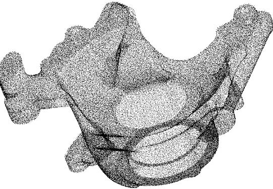
2.1 Point cloud data of water pump 5
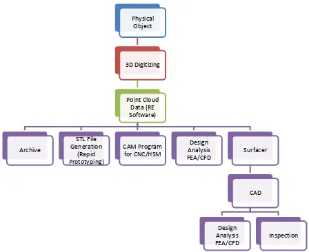
2.2 Comprehensive RE process chain 6
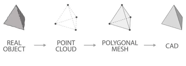
2.3
3D reverse engineering file conversion Process flow of computational analysis Mold for producing pattern with wax pattern Wax pattern tree for investment casting Refractory slurry invested over wax pattern
Refractory slurry invested over wax pattern dying in air Wax melted out of mold for investment casting
Mold for investment casting heated before pouring Pouring of an investment casting
Solidification of an investment casting
Breaking up of the mold for investment casting Investment casting final product
3.2 Intake manifold of Honda EX-5 motorcycle 30
3.3 ZScanner 700 (ZScan 1.3 User Guide) 31
RE process using ZScanner 700
The result of scanned intake manifold using ZScanner 700 3D CAD data of intake manifold in SolidWorks software Example of mold for investment casting
Simulation flow
Orthographic CAD drawing of intake manifold using SolidWorks Orthographic CAD drawing of Design 1 sprue using SolidWorks Orthographic CAD drawing of Design 2 sprue using SolidWorks Orthographic CAD drawing of Design 3 sprue using SolidWorks Orthographic CAD drawing of pouring cup using SolidWorks Orthographic CAD drawing of Design 1 using SolidWorks
x
Orthographic CAD drawing of Design 2 using SolidWorks Orthographic CAD drawing of Design 3 using SolidWorks AnyPRE process flow
Simulation of AnySOLVER Analysis of AnyPOST
xi
LIST OF ABBREVIATIONS, SYMBOLS AND
NOMENCLATURE
Al - Aluminium
Si - Silicon
C - Carbon
CAD - Computer Aided Drawing CAM - Computer Aided Manufacture RE - Reverse Engineering
CNC - Computer Numerical Control HSM - High Speed Machining FEA - Finite Element Analysis CFD - Computational Fluid Dynamics CAE - Computer Aided Engineering
1
1.1 Background
On 28th December 2013, the well-known Honda EX5 Dream 100 has roll out for its final production since its appearance in 1987. This motorcycles is also known with the code C100B and C100MB, and has been a very famous bike for the people whether young or old, rich or not, for 26 exhilarating years. Since then, 2,051,530 units been sold and make its way to Malaysian roads. This motorcycle has been lovable reliable bike that known for its toughness, low maintenance and easy to ride and become favourite to the people until now.
Due to this event, the demand for the automotive parts of this motorcycle peaked as the production of this motorcycle stopped. Most of the people look up for the spare parts of this motorcycle when they were having problems with this type of motorcycle. Because of the production of this motorcycle was no longer produced or done in mass production, the motorcycle workshop cannot provide sufficient spare parts for their customers to repair their beloved motorcycles.
Most of the automotive parts for this motorcycle made from casting process. The making of automotive parts in huge and mass production for this motorcycle usually uses investment-casting method. Investment casting is an industrial method and was also known as lost-wax casting. Investment casting allocates the production of parts with better accuracy, repeatability, versatility and integrity in a variety of metals and high-performances alloys. Investment casting can manufacture complicated shapes
INTRODUCTION
2 that would be difficult or impossible with die casting, yet like that process, it needs little surface finishing and only minor machining.
1.2 Problem Statement
Several problems might occur in producing automotive parts that no longer produced in mass production. First, the generation of the 3D CAD data of obsolete automotive part for this motorcycle might be difficult to be done. The full dimensions of the part will be hard to obtain, as the part is hard to get nowadays. To create this obsolete automotive part for this motorcycle using investment casting, the full dimensions for the generation of 3D CAD data must obtained precisely. Apart from that, the best precision and tolerance from investment casting product will be hard to obtain if the simulation for the investment casting mold does not take places before the investment casting processes are done. Without the analysis from the simulation, the presence of several types of defects on the investment casting product will occur. Therefore, the analysis from the simulation for the investment casting mold must be done before going through with the production of the product to make sure the best product from the investment casting can be made.
1.3 Objectives
The objectives for design and simulation of investment casting mold for obsolete automotive part that wants to be achieve are:
i. To design an obsolete automotive component of intake manifold.
ii. To simulate investment casting mold designs for obsolete automotive part.
3
1.4 Work Scope
To make sure the project that was carried out will achieve the objectives stated, which was to design and simulate the investment casting mold of obsolete automotive part, therefore the scope of work for the study proposed in this project will be simple, clear and efficiently organized. The work scopes of this project are:
i. Generating 3D CAD data for intake manifold of Honda EX-5 Dream motorcycle.
ii. Optimizing and improving the current mold design of investment casting by generating several 3D CAD data of mold designs based on selected part. iii. Simulation of the mold design of investment casting using AnyCasting
software.
4 A literature review is a process of evaluating text written or published information to reflect on the critical points of current knowledge including substantive result, as well as theoretical and methodological contributions to a particular topic. Literature review may considered by research through books, journal, article, thesis, website or any other resources. In this project, the literature review will be focusing on the several topics that related to this pr oject.
2.1 Reverse Engineering
Reverse engineering (RE), is defined as legally authorized technique of copying a technology which begins with an existing product and works backward to figure out how it does and what it does in order to duplicate or enhance the project. (Hambali Bin Boejang, 2013) In other word, reverse engineering is a method that consists of discovering the technological principles of a device, object or system through analysis of its structure, function and operation.
RE regularly occupies disassembling something that is a mechanical device, electronic component, computer program, or biological, chemical or organic matter and analyzing its components and working in detail. This is either purposes of maintenance or to support creation of a new product or program that does the same thing, without simply duplicating or using the original. The RE process is consisting of:
LITERATURE REVIEW
5 i. Digitization of the object, data capturing.
ii. Processing of measured data. iii. Creation of CAD model. iv. Prototype.
2.1.1 Point Cloud Data and Digitizing
The RE method begins with digitizing or scanning of an object or part for the creation of digital illustration of the object itself. This illustration known as point cloud as follows:
Figure 2.1 - Point cloud data of water pump.
6
2.1.2 Reverse Engineering Process Chain
The development of the product starts with a physical mock-up made out of clay or wood. The early stage of RE started with digitizing of an object for data or information acquirement. The comprehensive RE process chain illustrated as follows:
Figure 2.2 - Comprehensive RE process chain.
7 Figure 2.3 - 3D reverse engineering file conversion.
2.1.3 Application of Reverse Engineering
There are many applications of reverse engineering that important nowadays. Most of them are focused on the design of a new product, reproduction of an existing product and improving quality and efficiency of existing product or parts. These are some major applications of reverse engineering according to different field:
• Manufacturing engineering.
i. To create 3D virtual model of an existing physical part for use in 3D CAD, CAM, CAE or other software.
ii. To make a digital 3D record of own products. iii. To assess competitors’ products.
iv. To analyze the working of a product. v. To identify potential patent infringement.
• Software engineering.
8
• Chemical engineering.
i. To determine chemical composition.
ii. To substitute or improve recipes to stimulate or improve the products performance.
• Film-Entertainment industry.
i. Animated objects are imparted motion using the reverse engineered human skeletons.
• Medical field.
i. Applications in orthopaedic, dental and reconstructive surgery.
ii. Imaging, modelling and replication of patient’s bone structure.
iii. Models can be viewed and physically handled before surgery,
benefiting in evaluation of the procedure and implant fit in difficult cases.
iv. Less risk to the patient and reduced cost through saving in theatre time.
2.2 CAD/CAM
Computer Aided Design (CAD) includes the use of computer hardware and graphics software to create design drawings. Modern CAD tools allow the designer to easily produce very precise, accurate and realistic images of products to be manufactured.
9
2.2.1 SolidWorks Software
The SolidWorks CAD software is a mechanical design automation application that lets designers quickly sketch out ideas, test with features and dimensions, and generate models and detailed drawings.
2.2.1.1SolidWorks Fundamentals
A SolidWorks model consists of 3D geometry that describes its edges, faces, and surfaces. The SolidWorks software helps to design models quickly and precisely. SolidWorks models are defined by 3D design and also based on components.
SolidWorks employs a 3D design approach as when a part was designed, a 3D model is created from the initial sketches to the final result. 2D drawings can also be generated or mate components consisting of parts or subassemblies to create 3D assemblies from this model. 2D drawings of 3D assemblies can also be created from the models.
One of the most powerful features in the SolidWorks application is that any modification made to a part was reflected in all associated drawings or assemblies.
2.2.1.2Parts
Parts are the building blocks of every SolidWorks model. Each assembly and drawing created was made from parts.