UNIVERSITI TEKNIKAL MALAYSIA MELAKA
DESIGN AND OPTIMIZATION OF RUNNER AND GATING
SYSTEMS FOR THE PERMANENT MOLD CASTING
This report submitted in accordance with requirement of the Universiti Teknikal Malaysia Melaka (UTeM) for the Bachelor Degree of Manufacturing Engineering
(Manufacturing Design) (Hons.)
by
MOHAMMAD AIZRULSHAH BIN KAMARUDDIN B050910203
790407-01-6397
DECLARATION
I hereby, declared this report entitled Design and Optimization of Runner and
Gating for Permanent Casting is the results of my own research except as cited in
the references.
Signature : ……….
Author’s Name : MOHAMMAD AIZRULSHAH BIN
KAMARUDDIN
APPROVAL
This report is submitted to the Faculty of Manufacturing Engineering of UTeM
as a partial fulfillment of the requirements for the degree of Bachelor of
Manufacturing Engineering (Manufacturing Design) (Hons.). The member of
the supervisory committee is as follows:
---ABSTRAK
Aliran bendalir memainkan peranan penting dalam menghasilkan acuan tuangan
yang berkualiti tinggi . Aliran bendalir dipengaruhi oleh halaju tuangan dan
pelari(runner) dan reka bentuk pintu (gating) acuan. Ia akan menentukan sama ada
aliran adalah gelora atau lamina. Proses reka bentuk adalah peringkat yang paling
penting dalam mana-mana pengeluaran produk yang sama seperti membuat acuan
kekal . Amalan semasa adalah kaedah cuba jaya untuk mendapatkan reka bentuk
acuan kekal yang terbaik. Dengan menggunakan perisian analisis cecair dinamik,
proses mereka bentuk pelari(runner) dan pintu (gating) boleh dipermudahkan.
Matlamat utama kajian ini adalah untuk mereka bentuk dan mengoptimumkan
pelari(runner) dan pintu (gating) untuk acuan tuangan kekal. Kaedah yang
digunakan dalam kajian ini adalah Solidworks 3D model dan ANSYS FLUENT
perisian pengiraan analisis bendalir dinamik. Model aliran gelora telah digunakan
untuk mensimulasikan aliran aluminium lebur LM6. Empat rekabentuk konsep telah
dianalisa oleh ANSYS FLUENT daripada segi tekanan statik, magnitud halaju,
tenaga kinetik bergelora, tenaga dalaman dan nombor sel Reynolds. Keputusan yang
diperolehi daripada simulasi dioptimumkan untuk mewujudkan acuan yang
sempurna. Kesimpulannya acuan kekal bagi proses acuan tuangan gravity telah
direka dan dioptimumkan dan ia telah memenuhi objektif projek. Analisis simulasi
adalah alat yang sangat berguna bagi jurutera yang boleh digunakan sebagai rujukan
ABSTRACT
Fluid flow plays a major role in producing good quality casting. The fluid flow is
influenced by the pouring velocity and the runners and gating design of the mold.
The design process is the most important stages in any product manufacturing same
as permanent mold making. The current practice is the experimenting method to
predict the best design. By using computational fluid dynamic analysis the process
of designing runners and gating can be improved. The main objective of this paper is
to design and optimize the runner and gating systems for permanent mold casting.
The method use in this paper is Solidworks 3D modeling and ANSYS FLUENT
computational fluid dynamic analysis software. Transient, turbulence flow model
has been applied to simulate the flow of molten aluminum LM6. The ANSYS
FLUENT analyzed 4 runners and gating design concept from the aspect static
pressure, velocity magnitude, turbulent kinetic energy, internal energy and cell
Reynolds numbers. The results gained from the simulation are optimized to create a
perfect mold. As a conclusion a permanent mold casting was designed and
optimized and it fulfilled the objective of the project. The simulation analysis is a
very powerful tool for engineers that can be used as a reference to improve
DEDICATION
To beloved wife
Azlinda Mohamad
To my kids
Muhammad Izzu Syahmi and Maryam Kayyisah
And to my parents
Hj Kamaruddin Hj bin Hj Idris
ACKNOWLEDGEMENT
I would like to thank my supervisor Dr Taufik for the support, guidance and
understanding during the making of this report. Thank to my wife Azlinda for the
patience and understanding. Thank also to my colleague for the idea, discussion and
TABLE OF CONTENT
2.1 Casting And Its History 5
2.2 Permanent Mold Casting 8
2.2.1 Advantages Of Permanent Mold Casting 9
2.3.1.1. Volume 9
2.3.1.2. Tolerance and Surface finish 9
2.3.1.3. Cost 10
2.2.2 Limitation Of Permanent Mold Casting 10
2.2.3 Defect In Permanent Mold 11
2.2.4 Permanent Mold Casting Process 13
2.3 Design 13
2.3.1 Rigging System Design 15
2.3.2 Riser Design 16
2.3.3 Feeding System In Riser Design 18
2.3.4.1 Gating Design Variables 19
2.3.4.2 Principle of fluid flow 20
2.3.4.3 Ideal gating design 22
3.3. Stage 2: The Design Stage 32
3.4. Stage 3: Analysis And Result 34
3.5. Stage 4: Report Preparation and Presentation 34
3.6. The Design Concept Sketches 35
3.7. Conclusion 36
CHAPTER 4: RESULT & DISCUSSION
4.1 The Design concept 37
4.1.1 Design concept 1 38
4.1.2 Design Concept 2 39
4.1.3 Design concept 3 39
4.1.4 Design concept 4 39
4.2 Ansys 14 Fluent Simulation 40
4.2.1 Ansys Fluent models 40
4.2.2 Ansys Fluent Material 40
4.2.2.2 Wall Material 41
4.2.2.3 Cell Zone Condition 41
4.2.2.4 Boundary Condition 41
4.2.3 Ansys Simulation Result Data 43
4.2.3.1 Design Concept 1 43
4.2.3.2 Design Concept 2 47
4.2.3.3 Design Concept 3 52
4.2.3.4 Design Concept 4 57
4.3 Ranking 61
4.4 Optimization 63
4.4.1 The Runner And Gating Concept Design 63
4.4.2 Ansys Simulation Result Analysis 65
4.4.3 Ansys Fluent Flow Analysis Optimized 66
4.5 SolidWorks Modelling 70
4.6 Summary of Result 72
CHAPTER 5: CONCLUSION & FUTURE WORKS
5.1. Conclusion 73
5.2. Future works 74
REFERENCES 75
LIST OF TABLES
4.1 LM6 Properties 41
4.2 Steel properties 41
4.3 The inlet Condition value 42
4.4 The outlet condition 42
4.5 Simulated Ansys Fluent data 43
4.6 Simulated Data 50
4.7 Simulated Data 55
4.8 Simulated Data 59
4.9a Design 1 and 2 simulated data 61
4.9b Design 3 and 4 simulated data 61
4.10 Maximum Value comparison 62
4.11 Ranking 62
4.12a Ansys Fluent Result for runner and gating optimize concept 66
4.12b Ansys Fluent Result for runner and gating optimize concept 66
LIST OF FIGURES
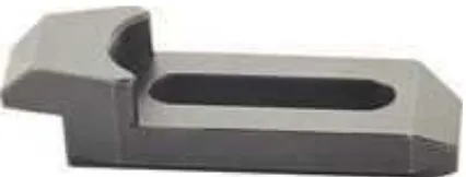
1.1 Gooseneck Clamp 4
2.1 The important development in casting process 6
2.2 Expendable Mold process tree 7
2.3 Process tree under permanent mold casting. Yellow indicates the
scope of study
8
2.4 Approximate values of surface roughness and tolerance on
dimensions typically obtained with different manufacturing
processes. ECM, electro-chemical machining; EDM, electrical
discharge machining
9
2.5 Differences between manufacturing process 10
2.6a Example defect in the casting process 12
2.6b Example of common defects hot tear in casting. Which the
defect can be minimized or eliminate with proper design and
preparation of molds
12
2.7 Directional and progressive solidification in a casting equipped
with a riser
17
2.8 Basic component of a single gating system for a horizontal
parted mold
19
2.9 Schematic illustrating the application of Bernoulli’s theorem to a
gating system
22
2.10 Poor top gates and side-fed running system, compared with (b) a
more satisfactory bottom-gated and top-fed system.
2.11 (c) Poor system gated at joint and (d) recommended economical
and effective system
23
2.12 Comparison of flow patterns in two vertical gating systems. (a) Poorly designed system. (b) Properly designed system using a
tapered runner that equalizesflow through the ingates
24
2.13 Schematic showing the advantages of a tapered sprue over a
straight-sided sprue. (a) Natural flow of afree-falling liquid. (b) Air aspiration induced by liquidflow in a straight-sided sprue. (c)
Liquidflow in a tapered sprue
25
2.14 Schematic illustrating fluid flow around right-angle and curved
bends in a gating system. (a) Turbulence resulting from a sharp
corner. (b) Metal damage resulting from a sharp corner. (c)
Streamlined corner that minimizes turbulence and metal damage
26
2.15 Goose neck clamp
2.16 Technical drawing and dimension of the gooseneck clamp 27
3.1 Project Framework Flow Chart 30
3.2 SolidWorks 3d modelling flow chart 33
3.3 Mold Design outline with SolidWorks 33
3.4 ANSYS 14 Fluent procedures flowchart 34
3.5 Sketch 1 35
3.6 Sketch 2 36
3.7 Sketch 3 36
4.1 Design Concept 1 37
4.2 Design Concept 2 38
4.3 Design Concept 3 39
4.4 Design Concept 4 39
4.5 Contour of static pressure 43
4.6 Contour of velocity magnitude 44
4.7 Contour of turbulence kinetic energy 45
4.8 Contour of internal energy 45
4.9 Flow simulated 46
4.10 Temperature vs Time Chart 47
4.11 Contour of static pressure 48
4.12 Contour of velocity magnitude 49
4.13 Contour of turbulence kinetic energy 49
4.14 Contour of internal energy 50
4.15 Flow simulated 51
4.16 Temperature vs Time Chart 52
4.17 Contour of static pressure 53
4.18 Contour of velocity magnitude 53
4.19 Contour of turbulence kinetic energy 54
4.20 Contour of internal energy 55
4.21 Velocity Streamline Flow 56
4.23 Contour of static pressure 57
4.24 Contour of velocity magnitude 58
4.25 Contour of turbulence kinetic energy 58
4.26 Contour of internal energy 59
4.27 Streamline Flow 60
4.28 Temperature vs Time Chart 61
4.29 Gating and runner optimized design 1 63
4.30 Gating and runner optimized design 2 64
4.31 Gating and runner optimized design 3 65
4.32 Ansys Fluent Streamline for optimized 66
4.33 Temperature vs Time Chart 67
4.34 Streamline Flow for concept 2 optimized 67
4.35 Temperature vs Time Chart 68
4.36 Streamline Flow for concept 3 optimized 68
4.37 Temperature vs Time Chart concept 3 optimized 69
4.38 Mold in close position 71
4.39 Mold Exploded view 71
CHAPTER 1
INTRODUCTION
This chapter discusses briefly the design and optimization of runner and gating
system for the permanent mold. This chapter of the report briefly discusses the
project background, problem statement, objective and scope.
1.1 Project Background
Casting is an economical and oldest manufacturing process in producing or
reproducing complex part in mass numbers. The first metal casting was found to be
made during the period from 4000 to 3000 BC using stone and metal to cast copper
and bronze (Kalpakjian and Schmid, 2006). Casting is a process in which molten
metal is poured into a cavity of a mold which are split or broken apart to extract the
solidified metal cast(Boothroyd et al. 2002). Designing a mold used in casting is
considered as an art and science. There is no exact formula or parameter can be
used. It depends on the mold designer experiences, trial and error. Casting is divided
into 2 categories which is non permanent and permanent molds. This report covers
the designing and the optimization of runner and gating system for permanent mold
casting.
Permanent mold casting is a method used to cast product or part using permanent
mold or non expendable mold unlike sand casting where the use of expendable mold
expendable mold means that the mold is usually made from metal. The same
guidelines and rules use in designing a sand casting are applied in designing the
permanent mold. Except that in sand casting if there is an error or modification in
the design the mold can be crushed and reconstructed, this method did not apply to
permanent mold where it will require metal cutting and reshaping (Shamasundar et
al., 2010.). This will require cost therefore permanent mold need to be designed
carefully. Due to the material used for making the mold, it usually being used to cast
non ferrous alloy and some limited application for casting cast iron. Typical material
can be cast using permanent mold is aluminum, zinc, brass, copper, lead and even
gray cast iron. The benefit of using permanent mold casting is that the high
production runs due to faster cooling rate than sand. Permanent mold casting also
produces a product with high dimensional accuracy, near net shape and use less raw
material. Reasonable price cost can be achieved from the high production rate with
metal molds especially the water cooled molds compare to sand or investment
casting (Butler, 1998). Limitation of permanent mold casting is that not all shapes
can be cast using it, but with the combination of detachable and expendable core the
potential is limitless.
Defect effecting sand casting also applies to permanent mold casting such as
porosity and shrinkage. In order to eliminate the defect, the mold to be designed
carefully. Design is the critical step in the development of cost effective, high
quality casting. In designing a good permanent mold the part geometry plays a big
role in effecting the load carrying functionality of the casting but also the mold
construction (Stoll, 2009). The main purpose of designing the molds is to
concentrate liquid solid contraction until to the last portion of the casting to solidify
(Lampman, 2009). In the production of permanent mold the design or the
development stage use a lot of resources but quickly offset by the high production
run. A Goose neck machine clamps used for this study. Then the molds are design
using CAD software, the designed mold were tested using an analysis software.
Later the design will go optimization process. This project presents the design of
permanent mold use for casting a production tooling. The study on making a
permanent mold will give a lot in sight in the best method in the manufacturing of
1.2 Problem Statement
Designing permanent molds for casting can be considered as art and science.
Runners and the gating system are the most important part of the mold. There a
numerous guideline can be used for designing a mold but the position and size of the
runner and gating depended on the part want to cast. At the moment the current
practice in mold construction is an experimenting method where base on trial and
error. The trial and error method solely depended on the design engineers
knowledge and experience. However this practice is time consuming and high cost.
In this report the product use for study is a Goose neck machine clamp. Finding the
position and size of the runner and gating system is crucial to produce defect free
product and near net shape as possible. This project presents the design of
permanent molds, design and analyze using Computer Aided Engineering software.
1.3 Objective
1.3.1 To investigate the design parameter of a permanent mold casting for Goose
neck machine clamp.
1.3.2 To analyze and optimize the permanent mold casting Computer Aided
Engineering software.
1.3.3 To design a permanent mold casting for Goose neck machine clamp.
1.4 Scope
This report only focuses on mold design of a production tooling called Goose neck
machine clamp. The report also considers the existing optimum parameters for
casting molds. The mold geometry design using SolidWorks design software and
analyze using the ANSYS FLUENT software. The mold designed is for gravity
feed casting. Aluminum LM6 and stainless steel is use as the molten metal and mold
Figure 1.1 Goose neck clamp
1.5 Report Structure
Chapter 1 describes the background of the study. Chapter 2 consists of the literature
review and chapter 3 the methodology of the research project. Chapter 4 explained
CHAPTER 2
LITERATURE REVIEW
This chapter consists of the information gathered regarding the project title which is
Design and optimization of runner and gating system for permanent mold casting.
The information collected from books and previous study. Tools and software used
in this project also will be explained in this report.
2.1 Casting And Its History
Casting can be considered as an oldest manufacturing method know to man. It's a
method used to produce parts in mass numbers. Casting was first used around 4000
B.C to cast ornament and copper arrow head (Kalpakjian and Schmid, 2006).
Copper is the first metal to be cast and usually the component made were weapon
arrow head or axes. During the Bronze Age (3000-1500 BC) alloys such as tin
bronze and arsenical copper were developed. Alloying, as well as reducing the
melting temperatures required, improved the strength of the finished product and
helped to oxidize the melt, enabling a better surface finish and higher level of detail
to be obtained because of the enhanced fluidity (Jolly 2003).
There some archeological find and the oldest casting in existence is a copper frog
dated 3200 BC discovered in Mesopotamia. One of the first cast iron objects, a 270
kg tripod, was cast by Chinese in 600 BC. A colossal statue of the Great Buddha in
There is also some developed at about the
small object mainly
investment casting. T
process.
Figure 2.1
some archaeological evidence that the “lost w
bout the beginning of the Bronze Age. This method
nly jewelry (Jolly 2003). Later on this method
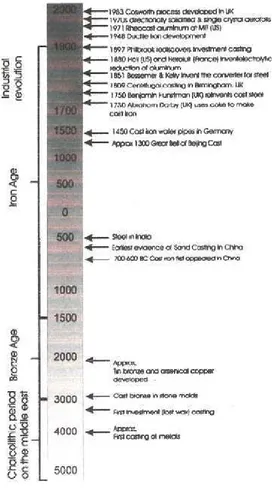
. The figure 2.1 below show the important deve
2.1 The important development in casting process (Jolly
ost wax” process was
hod was used to cast
hod was renamed the
velopment in casting
Casting can be used to produce a wide variety of product with complex shape and it
only involves one major manufacturing method. Casting involves pouring molten
metal in a mold cavity that configured to the shape and dimension of the intended
finish product. Casting can be divided into 2 major categories which is expandable
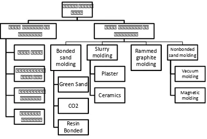
and non expandable mold. Figure 2.2 below illustrates the process tree under the
expandable mold process
Figure 2.2 Expendable Mold process tree
As the name implies the expendable mold process use material that are expendable
such as sand or other granular mold material. In expendable mold casting with
permanent pattern the mold needed be split into in order to remove the pattern
before the actual pouring process is done. Due to the title of the project the
2.2 Permanent Mold Casting
Permanent mold casting is a casting process that uses non expendable that are either
made from metal or graphite. Permanent mold processes involve the production of
castings by pouring molten metal into permanent metal molds using gravity, low
pressure, vacuum or centrifugal pressure and simple reusable cores are usually
made of metal (Lampman, 2009). The mold cavity and the gating system are
machined into the mold and become an integral part of the mold (Kalpakjian and
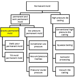
Steven, 2006). That's why the design of the mold is crucial. Figure 2.3 illustrated the
process tree under permanent mold casting process.
Figure 2.3 Process tree under permanent mold casting. Yellow indicates the scope of study.