“I/we verify that, I/we have read this report and from my/our opinion this thesis have fulfill the scope and quality requirement for Bachelor Mechanical Engineering
(Design and Innovation)”
Signature :………
1st Supervisor Name :………
Date :………
Signature :………
2nd Supervisor Name :………
ii
APPLICATION OF DESIGN OF EXPERIMENT FOR BELL CASTING PROCESS
NURUL FARHA BT ABDUL RAHMAN
This report is submitted to the Faculty Mechanical Engineering in partial to fulfill the requirement for Bachelor Mechanical Engineering
(Design and Innovation)
FACULTY OF MECHANICAL ENGINEERING UNIVERSITI TEKNIKAL MALAYSIA MELAKA
iii
“I hereby declared that this report is a result of my own work except for the works that have been cited clearly in the references.”
Signature : ………
Name : Nurul Farha Bt. Abdul Rahman
iv
v
ACKNOWLEDGEMENT
First and foremost, my greatest gratitude to ALLAH S.W.T for giving me strength and opportunity to complete this report.
I would like to extend my appreciation to En. Mohd Ruzi bin Hj. Harun for his continuous support, concern, positive criticism and invaluable advice that helped me a lot throughout this project. Special recognition to all of every single especially En. Junaidi, En.Asrul, En. Kamil and individuals that helps me in any kind of assist in my way to finish up my project during my time having problem and difficulties.
vi
ABSTRAK
vii
ABSTRACT
viii
TABLE OF CONTENT
CHAPTER TITLE PAGE
DECLARATION iii
DEDICATION iv
ACKNOWLEDGEMENT v
ABSTRAK vi
ABSTRACT vii
TABLE OF CONTENT viii
LIST OF TABLES xi
LIST OF FIGURES xii
LIST OF APPENDICES xiv
ABBREVIATION xv
1 INTRODUCTION
1.1 Background 1
1.2 Problem Statement 1
1.3 Objectives of project 2
1.4 Scopes of project 2
1.5 Significant of Project 2
2 LITERATURE REVIEW
2.1 Introduction 3
2.2 Casting 3
2.4 Sand Casting and Its Operation 7
2.4.1 Type of Sand Molds 8
2.4.2 The Sand Casting Operation 9 2.4.3 Parameters involved in sand casting 11
2.4.3.1 Type of sand 11
2.4.3.2 Solidification of metal 12
2.4.3.3 Rate of pouring 13
2.4.3.4 Pouring techniques 13
2.5 Bell Casting 14
2.5.1 The Anchor 15
2.5.2 The Anvil 16
2.5.3 The Bell 17
2.6 Minitab Software 18
2.7 Design of Experiment (DOE) 19
2.7.1 Fractional Factorial Design 20
2.7.1.1 Resolution 20
2.7.2 The purpose of experimentation 21
2.7.3 Basis of experimentation 22
2.7.4 Definition of a designed experiment 22 2.7.5 The design of experiments process 22 2.7.6 DOE Process Step Complete
Description 25
2.8 Taguchi Method 29
2.8.1 Static Problems 29
2.8.2 Dynamic Problems 31
2.9 Summary 32
3 METHODOLOGY
3.1 Introduction 33
3.2 Methodology 33
3.2.1 Literature Review 34
3.2.2 Application of Minitab software 34
x
3.2.2.2 Data Type 35
3.2.2.3 Entering Data 36
3.2.2.4 Manipulating Data 36
3.2.2.5 Calculating with Data 37
3.2.2.6 Saving Data 37
3.2.3 Application Of DOE Software 38 3.2.2.1 Steps using DOE software 38 3.2.2.2 Steps using Taguchi Design in DOE 44 3.2.4 Experimental on Bell Casting 49
3.2.5 Result and Discussion 52
3.2.6 Conclusion 52
3.3 Project Flowchart 53
3.4 Gantt Chart
3.4.1 Gantt chart for PSM I 54
3.4.1 Gantt chart for PSM II 55
4 CASE STUDY AND EXPERIMENTAL
ON BELL CASTING 56
5 RESULT AND DISCUSSION
5.1 Introduction 57
5.2 Data Results 57
5.3 Standard of Operation in Bell Casting 63
6 CONCLUSION AND RECOMMENDATION
6.1 Conclusion 65
6.2 Future Recommendation 65
REFERENCES 66
xi
LIST OF TABLES
Table 2.1 Summarize of different types of casting, advantages, disadvantages and examples
Table 2.2 Fractional factor resolution and its ability Table 3.1 Factors studied in Bell Casting experiment Table 3.2 Half-fraction of 2k-p design
Table 3.3 Gantt chart for PSM I Table 3.4 Gantt chart for PSM II
Table 5.1 Data results for Bell Casting experiments
xii
LIST OF FIGURES
Figure 2.1 Outline of metal casting processes
Figure 2.2 Outline of production steps in a typical sand-casting operation Figure 2.3 Schematic illustrations of the sequences operations for sand casting Figure 2.4 Set of Bell casting
Figure 2.5 The finished, fettled castings: Anchor, anvil and bell Figure 2.6 Gate on the anchor in Bell casting
Figure 2.7 Anvil
Figure 2.8 Gate on the anvil in Bell casting
Figure 2.9 Demonstration of the shrinkage in small and large downgate Figure 2.10 Gate on the core of the bell on cope
Figure 2.11 The bell process
Figure 2.12 Casting process flowchart
Figure 2.13 Casting process cause-effect diagram Figure 2.14 P-Diagram for Static problem
Figure 2.15 P-Diagram for Dynamic problem Figure 3.1 Project’s methodology
Figure 3.2 Main window of Minitab. Figure 3.3 Data can be enter manually Figure 3.4 Menu for changing data types Figure 3.5 Main window of Minitab software Figure 3.6 Box where the furnace was heated Figure 3.7 Type of pattern chose for factors
Figure 3.8 Pattern upper part were placed together with under part Figure 3.9 Metal being kept to solidify
xiii Figure 5.1 Graph of Main Effects Plot for Slopes
Figure 5.2 Graph of Main Effects Plot for SN Ratios Figure 5.3 Graph of Response vs. Time to Melt
xiv
LIST OF APPENDICES
Appendix A DOE Process Tasks, Task Aids and who will take the responsibilities Appendix B Moulding process of a bell in Bell casting process
xv
ABBREVIATION
FKM Fakulti Kejuruteraan Mekanikal DOE Design of Experiment
B.C Before Century
OA Orthogonal Array
C-E Cause Effect
1
CHAPTER 1
INTRODUCTION
1.1 Background
In manufacturing process, productivity and quality of casting depend mainly on its process parameters such as casting temperature, filling time, holding pressure, holding time, and cooling rate. To estimate the most influential parameters in casting process, many trial and errors is used to identify the best parameters to manufacture a quality cast product. However, these methods demands extensive experimental work and result in a great waste of time and money. Thus, design of experiment appears to be an important way in estimation the most process parameters and process optimization in Bell casting operation for this project because this method can save both labor cost and time spent.
1.2 Problem Statement
2 Failure to control one of the process parameters can lead to give an impact in Bell casting operation. In order to overcome this failure, this project was to estimate the most influential process parameters and process optimization in Bell casting operation.
1.3 Objectives of project
The objective of this project is to estimate the most influential process parameters and process optimization in expandable mold casting which is sand casting using Bell casting operation and equipment.
1.4 Scopes of project
The main scope of this project was:
1.4.1 To study Bell casting process and its process parameters. 1.4.2 To study DOE and Minitab software.
1.4.3 To carry out empirical study on Bell casting process parameters that to be used as a Standard of Operation in FKM’s workshop lab.
1.5 Significant of project
3
CHAPTER 2
LITERATURE REVIEW
2.1 Introduction
Literature review is the most important step to retrieve information related with the topic chooses. Literature review can be done by searching all the information from internet, journals, books, and other sources. It is important to study or research before starting any development for better understanding regarding the topic chooses.
2.2 Casting
4 As in all manufacturing, each casting process has its own characteristics, applications, advantages, limitations and costs. Casting process are most often selected over other manufacturing methods because casting can produce complex shapes and with internal cavities or hollow sections. From casting, a very large part also can be produced in one piece.
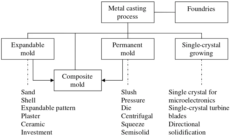
Almost all the metal can be cast in the final shape desired, often with only minor finishing operation required and because of this capabilities, it places casting among the most important net-shape manufacturing technologies. With modern processing techniques and the control of chemical composition, mechanical properties of castings can equal those made by other manufacturing process. Figure 2.1 below cited three methods of metal casting process used in manufacturing.
Figure 2.1 Outline of metal casting processes (Source: Serope Kalpakjian & Steven Schmid)
Metal casting process Foundries Expandable mold Composite mold Single-crystal growing Permanent mold Sand Shell Expandable pattern Plaster Ceramic Investment Slush Pressure Die Centrifugal Squeeze Semisolid
Single crystal for microelectronics Single-crystal turbine blades
5
2.3 Casting Processes
Various casting process have been developed over time, each with its own characteristics and applications, to meet specific engineering and service requirements. Large variety of parts and components are made by casting such as engine blocks, crankshafts, automotive components and powertrains.
There are 3 major classifications in casting practices. These classifications are related to mold materials, molding processes and methods of feeding the mold with molten metal.
The major categories are:
a) Expendables molds
It is typically made of sand, plaster, ceramics, and similar materials and generally is mixed with various binders for improved in mechanical, physical and chemical properties.
b) Permanent molds
Permanent mold are made of metals that maintain their strength at high temperatures. As the name implies, they are used repeatedly and are designed in such a way that the casting can remove easily and the mold used for the next casting.
c) Composite molds
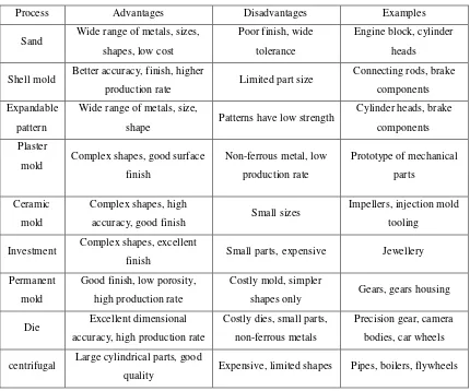
6 All casting process, its advantages, disadvantages and examples can be summarized as shown in Table 2.1 below:
Table 2.1 Summarize of different types of casting, advantages, disadvantages and examples
(Source: http://d.scribd.com/docs/1fm1ats4fjks6pn3ksin.pdf) [9]
Process Advantages Disadvantages Examples
Sand Wide range of metals, sizes, shapes, low cost
Poor finish, wide
tolerance
Engine block, cylinder
heads
Shell mold Better accuracy, finish, higher
production rate Limited part size
Connecting rods, brake
components
Expandable
pattern
Wide range of metals, size,
shape Patterns have low strength
Cylinder heads, brake
components
Plaster
mold Complex shapes, good surface finish
Non-ferrous metal, low
production rate
Prototype of mechanical
parts
Ceramic
mold
Complex shapes, high
accuracy, good finish Small sizes
Impellers, injection mold
tooling
Investment Complex shapes, excellent
finish Small parts, expensive Jewellery
Permanent
mold
Good finish, low porosity,
high production rate
Costly mold, simpler
shapes only Gears, gears housing
Die Excellent dimensional
accuracy, high production rate
Costly dies, small parts,
non-ferrous metals
Precision gear, camera
bodies, car wheels
centrifugal Large cylindrical parts, good
7
2.4 Sand Casting and Its Operation
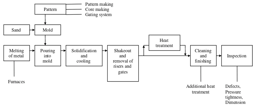
Sand casting was one of other method in casting processes and has been used for millennia. Sand casting is still the most prevalent form of casting. Molten metal is poured into a mold cavity formed out of sand (natural or synthetic). Basically, sand casting consist of placing a pattern in sand to make an imprint, incorporating a gating system, removing the pattern and filling the mold cavity with molten metal, allowing the metal to cool until it solidifies, breaking away the sand mold and lastly removing the casting. Figure 2.2 below illustrate the production flow in a typical sand casting operation.
There were several important factors in the selection of sand for mold with respect to its properties. Sand is fine, round grains that can be pack closely and thus form a smooth mold surface. But fine-grained sand can lower the mold permeability. Good permeability of mold and cores allows gases and stream evolved during the casting to escape easily. Furthermore, mold also should be in good collapsibility to allow the casting to shrink while cooling and to avoid defects in casting such as hot tearing and cracking.
Figure 2.2 Outline of production steps in a typical sand-casting operation (Source: Serope Kalpakjian & Steven Schmid) [1]
8
2.4.1 Type of Sand Molds
Sand mold can be characterized by the types of sand and by the method used to produce them. There are three basic types of sand molds: green-sand, cold-box, and no-bake molds. The most common mold material is green molding sand, which is mixture of sand in the mold is moist or damp while the metal is being poured into it. Green-sand molding is the least expensive method of making molds, and the sand is recycled easily for subsequent use. In the skin-dried method, the mold surfaces are dried, either by storing the mold in air or by drying it with torches. Because of their higher strength, these molds generally are used for large casting.
In the cold-box process, various organic and inorganic binders are blended into the sand to bond the grains chemically for greater strength. These molds are more accurate dimensionally than green-sand mold but are more expensive. In the no-bake mold process, a synthetic liquid resin is mixed with the sand, and the mixture hardens at room temperature. It was called as cold-setting processes because the bonding of the mold in this and in the cold-box process takes place without heat.
Pattern
9
Core
Core is a sand shape inserted into the mold to produce the internal features of the part such as holes or internal passages. Cores are placed in the cavity to form holes of the desired shapes. The common problem with core is that they may lack sufficient structural support in the cavity. A riser is an extra void created in the mold to contain excessive molten material. The purpose of this is feed the molten metal to the mold cavity as the molten metal solidifies and shrinks, and thereby prevents voids in the main casting.