PJP/2011/FKE (6A) S00824
DEVELOPMENT OF 4-LEGGED WALKING ROBOT AND MOVEMENT ALGORITHM
AMINURRASHID BIN NOORDIN
FAKULTI KEJURUTERAAN ELEKTRIK UNIVERSITI TEKNIKAL MALAYSIA MELAKA
DEVELOPMENT OF 4-LEGGED WALKING ROBOT AND MOVEMENT ALGORITHM
AMINURRASHID BIN NOORDIN
RESEACH VOTE NO: PJP/2011/FKE (6A) S00824
FAKULTI KEJURUTERAAN ELEKTRIK UNIVERSITI TEKNIKAL MALAYSIA MELAKA
i
ABSTRACT
(Keywords: cooperative mobile robots, distance maintenance, infra-red sensor, ultrasonic sensor)
This project focused on designing and developing a 4-legged walking robot prototype. The robot can move forward according to a unique pattern of movement using three servo motors for each leg. Firstly, the design of this robot was draw using SolidWorks Software and then being fabricate using rapid prototyping machine. Then the structure of the body and leg was analyzed in order to find a correct balance and to make sure the servo motor was capable to move the robot. The prototype robot consists of servo motors, Li-Po batteries and Mini Maestro 18 servo controller as the robot’s brain. The experimental studies were carried out to get the correct gait algorithm for the robot to be able to move forward and avoid obstacles. Then the robot accuracy and repeatability had been tested. This robot was able to move forward, detect and avoid obstacles without
falling and able to move at different surface or different terrain.
Key Researchers:
Aminurrashid bin Noordin (Head) Mohd Azli bin Salim Mohd Hanif bin Che Hasan Mohd Razali bin Mohamad Sapiee
Sulaiman bin Sabikan Zamani bin Md Sani
ACKNOWLEDGEMENT
iii
TABLE OF CONTENT
CHAPTER TITLE PAGE
ABSTRACT i
ACKNOWLEDGEMENT ii
TABLE OF CONTENTS iii
LIST OF TABLES vi
LIST OF FIGURES vii
1 INTRODUCTION 1
1.1 Background 1
1.2 Problem Statement 2
1.3 Objective 3
1.4 Scope 3
2 LITERATURE REVIEW 5
2.1 Preview 5
2.2 Example of Legged Robot 6
2.2.1 Andy Droid Robot 6
2.2.2 Mechanically Adaptive All Terrain Robot (MAAT-1) 7
2.2.3 R-hex Robot 7
2.3 Locomotion Technique 9
2.3.1 Static Locomotion 9
3 METHODOLOGY 12
3.1 First Milestone 13
3.2 Second Milestone 13
3.3 Third Milestone 14
3.4 Fourth Milestone 15
3.5 Fifth Milestone 16
3.6 Research Methodology 16
3.6.1 Link Transformation Matrix 17
3.6.2 Moving Forward Gait 17
3.6.3 Obstacle Avoidance Gait 17
3.6.4 Terrain Adaptability 18
3.6.5 Accuracy and Repeatability 18
4 PROJECT DEVELOPMENT 19
4.1 Hardware Development 19
4.1.1 Robot Prototype 20
4.1.2 Rapid Prototyping Machine 24
4.2 Electrical/Electronic Parts Development 25
4.2.1 Servo Controller Selection 26
4.2.2 Power Supply 27
4.2.2.1 Lithium Polymer (Li-Po) Battery 27
4.3 Software Development 28
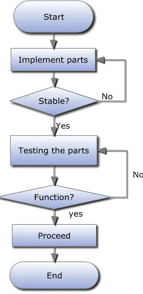
4.3.1 Program Flow Chart 30
5 RESULT AND ANALYSIS 31
5.1 Robot Design 31
v
5.3 Performance Analysis 34
5.3.1 Moving Forward Gait 34
5.3.1.1 Moving Forward Gait Description 36
5.3.2 Obstacles Avoidance Gait 36
5.3.2.1 Obstacles Avoidance Gait Description 38 5.3.3 Accuracy and Repeatability Test 38
5.3.4 Surface Suitability 40
6 DISCUSSION 42
7 CONCLUSION AND RECOMMENDATION 44
7.1 Conclusion 44
7.2 Future Recommendation 45
7.3 Project Potential 45
REFERENCES 46
LIST OF TABLES
TABLE TITLE PAGE
2.1 Comparison between Robots 8
5.1 D-H Table 32
vii
LIST OF FIGURES
FIGURE TITLE PAGE
1.1 Example of 4-legged Robot (Courtesy from Robot Trossen forum,
2010) 2
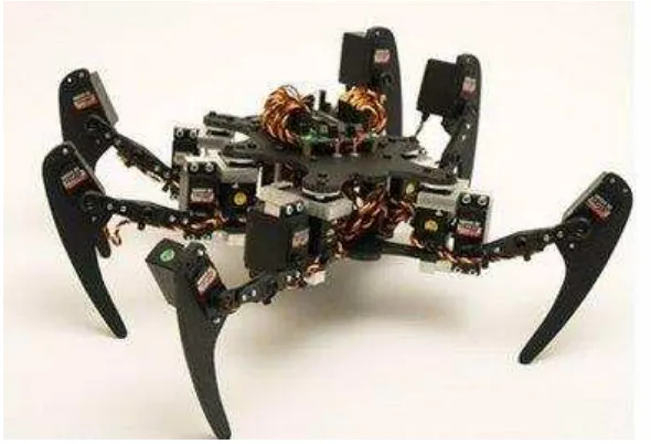
1.2 Example of 6-legged Robot (Courtesy to Curious Inventor Website) 2
2.1 Andy Droid Robot 5
2.2 MAAT-1 6
2.3 R-Hex Robot 7
2.4 Static Locomotion 9
2.5 Dynamic Locomotion 10
3.1 Methodology Flowchart 11
3.2 Integration Flowchart 13
3.3 Algorithm Flowchart 14
3.4 Experiment Flowchart 15
3.5 Experiment Procedure 17
4.1 Design Process 18
4.2 General Idea of the Robot 19
4.3 First Design of the Robot 20
4.5 Robot's Feet 21
4.6 Robot's Feet with Rubber Pad 21
4.7 Front Side of Servo Bracket 22
4.8 Back Side of Servo Bracket 22
4.9 Rapid Prototyping Machine 23
4.10 U-joint in Drawing 24
4.11 Robot Feet Drawing 24
4.12 Robot Base Drawing 24
4.13 SC16A (Courtesy to Cytron Website) 25 4.14 SK40C (Courtesy to Cytron Website) 25 4.15 Mini Maestro 18-Servo Controller (Courtesy to Pololu Website) 26
4.16 LiPo 7.4V 1300mAH Battery 27
4.17 LiPo 7.4V 2200mAH Battery 27
4.18 Pololu Servo Status 28
4.19 Pololu Script 28
4.20 Programming Flowchart 29
5.1 Autonomous 4-legged Robot 30
5.2 Link Frame Assignment 31
5.3 Legs Representation 33
5.4 Moving Forward Gait 34
ix
5.6 Obstacles Avoidance Gait 36
5.7 Graph of Accuracy and Precision of the Robot 38
INTRODUCTION
1.1 Background
Robotic technology has increasing rapidly. Mobile robots and artificial intelligence era had colored the robotic field nowadays. A lot of research had been conducted by researchers in university and multinational companies, and even the military, to understand the high mobility and stability of autonomous robot on rough terrain. Mobile robots are very useful in a situation when human are impossible or dangerous to operate. An example of the application using mobile robot is the scanning of buried land mine (T.W.Lee et al. 2002).
Mobile robots consist of two types which are wheel and legged robot. Wheeled robots are more common as they are easier to design and build. The cost of building a wheeled robot is generally low or cheaper. However, the wheeled robots are more suited to application on fairly even terrains as they are less adept when crossing uneven or rough terrains. Legged robots are trickier to design and built as compared to the wheeled robot. This is due to the complexity in designing the actuator and joint. But to build a leg robot, the stability factor and also the coordination of movement of the leg robot must be consider (T.W.Lee et al. 2002).
2
efficiencies not only from the requirement of static stability, but also owing largely to the many degrees of freedom in their legs. Their legs’ complexity, coupled with the large mass of many actuators, limit the robot’s behavior and lend the robots to frequent breakdowns.
Figure 1.1: Example of 4-legged Robot (Courtesy from Robot Trossen forum, 2010)
Figure 1.2: Example of 6-legged Robot (Courtesy to Curious Inventor Website)
1.2 Problem Statement
researchers tend to build a 6-legged robot since it quite easy to find the right balance for their robot. For a 4-legged robot, when one of the legs is lift to move forward, stability of the whole robot will affected. Therefore, to drive the robot forward, unique kinematics coordination is needed. Good planning and programming will maximize the robot’s movement in the aspect of speed, distance and strength. The implementation of four legged actuated by 8 to 12 servomotors is clearly difficult to program and very expensive. Studies on the center of gravity for designed robot need to be carried out to ensure the robot will move properly and not falling (T.W.Lee et al. 2002).
1.3 Objectives
The main objectives in this project are:
i. To design and fabricate a legged robot.
ii. To develop gait for the robot so the robot can move forward.
iii. To develop an algorithm for obstacle avoidance during forward movement
1.4 Scope
The scope on this projects covers on:
iv. Design and analysis of 4-legged walking robot.
v. One leg consists of three servo motors which mean the leg has three degree of freedom (DOF) each. Therefore the total amount of servo motors used in this robot is 12.
vi. The robot controlled by Pololu Maestro 18-servo controller. vii. Rechargeable Li-Poly battery as power supply.
CHAPTER 2
LITERATURE REVIEW
2.1 Preview
A robot is a machine that senses, thinks, and acts. Thus, a robot must have sensors, processing ability that emulates some aspects of cognition, and actuators. Sensors are needed to obtain information from the environment (David Wettergree, 1995). Reactive behaviors such as the stretch reflex in humans do not require any deep cognitive ability, but on-board intelligence is necessary if the robot is to perform significant tasks autonomously, and actuation is needed to enable the robot to exert forces upon the environment. Generally, these forces will result in motion of the entire robot or one of its elements such as an arm, a leg, or a wheel.
An extract from the award-winning robotic science fiction book, ‘I-robot’ by Isaac Asimov:
1. A robot should never harm a human being.
2. A robot should obey a human being, unless this contradicts the first law.
3. A robot should not harm another robot, unless this contradicts the first or second law.
The British Robot Association (BRA) defines robot as:
2.2 Example of Legged Robot
Nowadays, there are many types of robots that have been used to simplify human task by using a robot. The current states of the art of robot are divided into several categories which are wheel and legged robot.
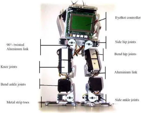
2.2.1 Andy Droid Robot
Based on past project by A. Boeing et al.(2004), Andy Droid robot is a bipedal robot which is weight around 1.4kg and 350mm tall. Andy has ten servo motors which mean the robot has ten degree of freedom (DOF) at its legs.For the structures of the robot, all links are made from 3mm thick aluminium flat plate and used to connect the plastic shafts of the servos directly to the next link. These connections result in a substanstial amount of inherent flexibility. Andy can be equipped with a number of sensors, including a color camera, PSDs, inclinometers, gyroscopes and pressure sensors. The pressure sensors are permanently mounted as Andy’s feet, which are constructed from three metal “toes”. Each toe has two strain gauges that are used to produce a voltage in proportion to the applied force.
6
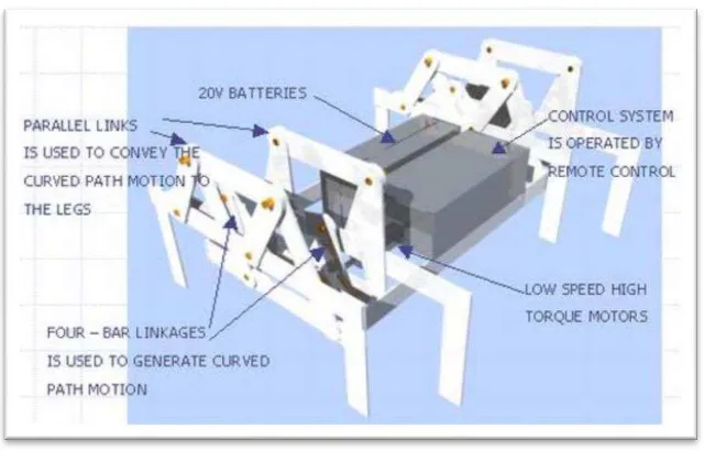
2.2.2 Mechanically Adaptive All Terrain Robot (MAAT-1)
Mark A. Tecson is a researcher and designer robot from Philippine had created 1 during his study in local university. Figure show the schematic design of MAAT-1. The MAAT – 1 has been designed to walk on all kinds of terrain. Its current design can enable it to scale up to 3 inch high obstacles. It was supposed to be capable of scaling up to 5 inch but due to its shifting center of gravity it slips under its own weight. He has no reliable measurement of the torque of the motor but he believes it can climb vertically if it uses suction cups. The limiting factor is the strength of the shafts and keys. He believes that if the robot use a much lighter aluminum angle bar instead of a flat bar it will be able to do so. It can only walk 20 degrees lateral to a slope the limit is due to the bending of the legs. Using lighter materials will also solve this problem. The robot has a maximum speed of 2 meters per minute; increasing the voltage up to 40 volts will further increase its speed. Finally, the legs are still subject to modifications which will increase its mobility, durability and reliability. (Mark A.Tecson, 2009).
Figure 2.2: MAAT-1
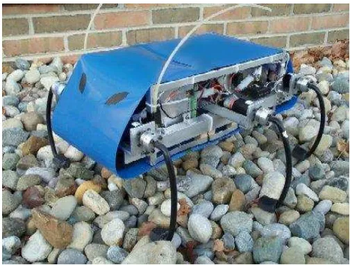
2.2.3 R-hex robot
Robert Full, of the University of California, Berkeley, has six legs that are attached outside its center of mass. This sprawled configuration grants the robot greater stability as it bounces over natural terrain.
“RHex is the only legged machine that can traverse rugged, broken ground rapidly (at or above the pace of one body length per second)”(Goldman, et.al ,2009)
In a typical jog, the legs support and propel the body by coordinating as two tripods—the two outer legs on one side and the middle leg on the opposite side.
“The hexapod RHex exhibits unprecedented mobility for a legged autonomous robot. Using an open loop feed forward control strategy, the machine runs at speeds exceeding five body lengths per second on even terrain, and negotiates badly broken and unstable surfaces, as well as stairs.”(Lin, et al, 2006)
RHex has become the model for a family of robots of Kodlab. Its progeny include, among others, the Aqua robot, which is basically Rhex with flippers for swimming; a two-armed, wall-climbing robot name d Dynoclimber; and SandBot.
Figure 2.3: R-Hex Robot
8
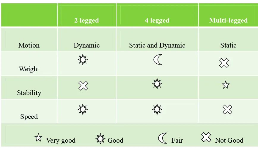
Table 2.1: Comparison between Robots
2 legged 4 legged Multi-legged
Motion Dynamic Static and Dynamic Static
Weight
Stability
Speed
Very good Good Fair Not Good
2.3 Locomotion Technique
The term locomotion actually means ability or the power to move. So, locomotion technique can be concluded as a method for something to move. For legged robot, basically there are two types of locomotion techniques which are static and dynamic locomotion.
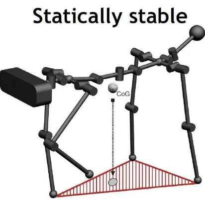
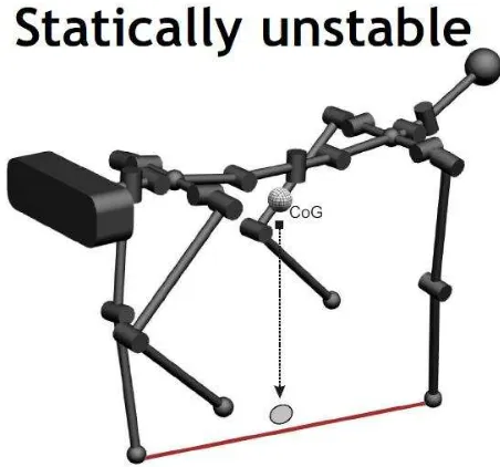
2.3.1 Static Locomotion
Static locomotion has only a kinematics measure of stability and can result in very slow forward movement. The legs of the robots can be considered manipulators so all manipulator's math models can be applied. To solve the direct kinematics problem we used the model of Denavit-Hartenberg. The inverse kinematics is in general more complex than the direct one, due to the fact that there isn't only one solution and in some cases there are an infinity number of solutions. To solve this problem the Jacobian's Math Method is the most used. (Kurt S. Aschenbeck et al).
Figure 2.4: Static Locomotion
For static locomotion technique, while lifting one of the legs, the other three legs are supporting the whole body weight. Even if all the joints not moving, the robot will not fall. However, this type of locomotion is slow and not efficient.
2.3.2 Dynamic Locomotion
10
A subset of dynamic walking is called passive dynamic movement. Most dynamic walking systems use active control to move the legs to the correct orientations for walking (hence active dynamic walking). Passive dynamic walking is characterized by a system where “gravity and inertia alone generate the locomotion pattern.”Passive dynamic movement can be achieved with maximum efficiency, as the vehicle uses its own forward momentum to propagate its next movement. Very little energy is lost from the system.
Figure 2.5: Dynamic Locomotion
Dynamic gait requires extremely little control in order for them to walk, and rely largely on the “natural” physics (mostly the effects of gravity) of the walker in order to produce a stable gait. This class of walkers demonstrates the fact that a walk need not have any gait planning, and requires very little energy. Basically, the model for dynamic gait planning is very complex and requires much time and experience in order to produce the motion stability of a quadruped robot.
METHODOLOGY
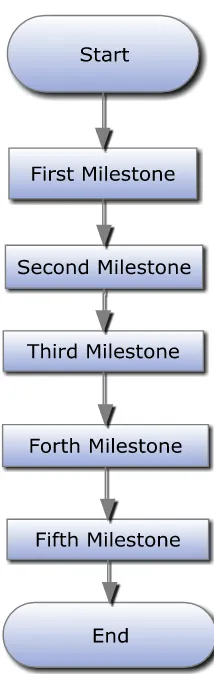
To develop this 4 legged robot from scratch, there are several numbers of tasks involved. Figure 3.1 shows the general idea about methodology in this project.
12
3.1 First Milestone
Activity 1: Project Objectives
Discuss with supervisor about the objectives of the project. So it is decided that the objectives of the projects are design and fabricated a legged robot and created gait of the robot so that the robot can move forward without falling.
Activity 2: Literature Review
To get general idea on how to build a legged robot, research about past projects and journal have been made. Several papers have been studied and compared.
3.2 Second Milestone
Activity 3: Design/Sketch the robot
Design robot leg and body structure using Solid Work software. One legged contains three joints which mean the robot has 3degree of freedom per leg. The robot design must considered basic stability factor in order to prevent the robot from falling if the robot not balances. The sketching of the robot was made part by part. After finished drawing all the part, all sections were then assembled into a complete robot.
Activity 4: Propose and discuss the design with supervisor
3.3 Third Milestone
Activity 5: Selection of component
Based on the design, torque of the robot was calculated to select suitable servo motors. Electrical component such as battery and servo controller were taken into account in term of suitability, performance and others.
Activity 6: Fabricated the robot
Discuss with supervisor to determine which method was suitable to fabricate the body and other part of the robot. So it is decided to fabricate the robot using rapid prototype machine (RPM).
Activity 7: Integration of electric/electronic and hardware to the robot All the parts were implemented on the robot. These parts were placed carefully so that it does not affect whole robot stability. After completely assembled, all the parts were tested in order to verify functionality of each part.