RESPONSIVE ATTENDANCE SYSTEM BASED ON THUMB SCANNING
BONG YU JING
This report is submitted in partial fulfillment of the requirements for the award of
Bachelor of Electronic Engineering (Industrial Electronics) With Honours
Faculty of Electronic and Computer Engineering Universiti Teknikal Malaysia Melaka ,
UNIVERSTJ TEKNIKAL MALAYSIA MELAKA
FAKULTI KEJURUTERAAN ELEKTRONlK DA KEJURUTERAA KOMPUTER
BO RANG PENGESAHAN STA T VS LA PO RAN
PROJEK SARJANA MUDA II
Tajuk Projek R ESPONSIVE A TTE DANCE SYSTEM B ASED 0 THUMB
SCANNING
Sesi Pengajian
Saya BO G YU JJNG
2 3
mengaku m e mbenarkan Laporan Projek Sarjana M uda ini disimpan di Perpustakaan dengan syarat-syarat kegunaan seperti berikut:
I. Laporan adalah hakmi lik U ni vers it i Teknikal Ma lays ia Me laka.
2. Pe rpustakaan dibenarkan m e mbuat salinan untuk tujuan pengajian sahaja.
3 . Perpustakaan dibenarkan m e mbu at salinan Iaporan ini sebagai bahan pertukaran antara institusi
pen gaj ian tinggi .
4 . Sila tandakan ( '1 ) :
D
SULIT*D
TERHAD* *0
TIDAK TERHADセᄋ@
*(Mengandungi makl umat yang berdarjah keselamatan atau kepentingan Malaysia seperti yang termaktub di dalam AKT A RAHSIA RASMI 1972)
**(Mengandungi maklumat terhad yang telah ditentukan oleh organisasi/badan di mana penyelidikan dijalankan)
dゥウセォ。ョ@ oleh:
(TANDATANGA PENULIS ) (C
" I hereby declare that this report is the result of my own work except for quotes as cited in the references."
Signature
... ... .. ... ... ... ....
セN@
Name: ....
セqngN@:DJ. J.™Q ... ... ... .
"I hereby declare that I have read this project report and in my own opinion this project report is sufficient in terms of the scope and quality for the award of Bachelor
of Electronic Engineering (Industrial Electronic) With Honors."
Signature :
....
セ@
.. . . ... .
. ENGR ..
セMZセᄋ@ セセセセ@ セ@
BTE ANAS... ... ... ... ... ... .. .. .... ... ... ...
Name
Lovingly dedicated to my
beloved family and friends
For being a
ACKNOWLEDGEMENT
I would like to take this opportunity to express my upmost gratitude towards those who have contributed in the completion of this project.
First and foremost , I would like to thank my helpful supervisors, Engr Siti
Aisyah bte Anas and Engr. Ranjit Singh Sarban Singh. They have given me wonderful supervision and support which truly aided in the smooth progression in the completion of this project. The encouragement and guidance given by them is much appreciated as without I would not be where I am today.
vii
ABSTRAK
viii
ABSTRACT
ix
TABLE OF CONTENTS
CHAPTER DESCRIPTION PAGE
PROJECT TITLE
VERICATION FORM ii
DECLARATION iii
DEDICATION v
ACKNOWLEDGEMENT vi
ABSTRAK vii
ABSTRACT viii
TABLE OF CONTENTS xi
LIST OFT ABLE xii
LIST OF FIGURE xiii
LIST OF APPENDIX xv
I INTRODUCTION 1
I. 1 Introduction
1.2 Objective 2
1.3 Problem Statement 2
1.4 Scope of Work 3
1.5 Project Planning 5
II LITERATURE REVIEW 8
2.1 Existing Attendance System 8
x
2.1.4
Magnetic Stripe Attendance Taking System10
2.1 .5
Smart Card Attend ance Taking System10
2.1.6
Radio Frequency Identification Attendance11
Taking System
2.1.7
Biometric Attendance Taking System12
2.2
Comparison between Existing Attendance Systems13
2.3
Fingerprint Processing Process13
2.3 .1
Capturing of Fingerprint Image15
2.3.2
Preprocessing of Fingerprint Image18
2.3.3
Recognition of Minutiae19
2.3.4
Post Processing of Minutiae20
2.3.3
Matching of Minutiae20
2.4
Structured Query Language21
III METHODOLOGY 23
3.0
System Overview23
3.1
System Operation24
3.2
Thumbprint Modules Comparison28
3.3
Expected Result29
IV RESULT AND DISCUSSION 34
4.0
Overview34
4.1
Hardware34
4.2
Software40
4.2.1
Responsive Attend ance System Graphic User40
Interface
4.2.2
Data Transfer Graphic User Interface45
4.2.3
Database45
v
CONCLUSION5.1 5.2
Co nclusion
Future Recommendation
5.2. 1 Web-based Monitoring System
49
49
49
50 5.2.2 Storage Capacity of the Standalone Device 50
5.2.3 Statistical Report 50
5.2.4 Rechargeable Battery 51
REFERENCES
APPENDIX A
52
55
xi i
LIST OFT ABLE
TABLE 2 . 1 C OMPAR ISON TABLE OF EX ISTING A TIENDA CE SYSTEMS I TERM OF CO VENIE CE, TIME
CONS UMPTION, ACC URACY AND RELIABILITY .. ... . .. .... ... ... .. ... . .. .. .... .... .. ... .... .... ... ... .. .. ... .. .. 13
xiii
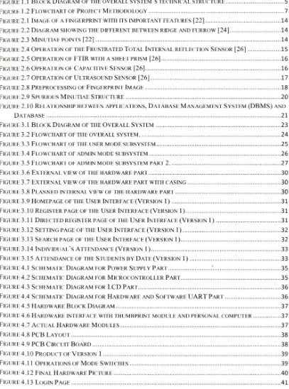
LIST OF FIGURE
FIGURE I . I BLOCK D IAGRAM OF TH E OVERALL SYSTEM ·s TECH ' ICA L STRUCTURE ... ... ... .... 5
FJGURE 1.2 FLOWCHART OF PROJECT METHODOLOGY ... ... .... ... ... .. ... ... .... . ... ... .. .... ... 7
FIGURE 2.1 IMAGE OF A Fl GERPRINT WITH ITS IMPORTANT FEATURES [22) ... .. .... 14
FIGURE 2.2 DIAGRAM SHOWING THE DIFFERENT BETWEE RIDGE A D FUR ROW [24) . .... ... ... .. .... .. ... 14
FIGURE 2.3 MIN UTIA E POINTS [22) . ... ... .. .... ... ... .. ... .. ... .. ... 14
FIGURE 2.4 OPERATION OF THE FRUSTRATED T OTAL INTER AL REFL ECTJON SENSOR [26) .... ... 15
FIGURE 2.5 OPERA T IO OF FTI R WITH A SHEET PRISM [26) . .. .. ... .. .... ... .. .. .... ... 16
FIGURE 2 .6 0PERATIO OF CAPACITIVE SENSOR [26). ... ... ... ... .. ... .... ... ... .. ... . .. ... ... ... . ... 16
FIGURE 2.7 OPERA T IO OF ULTRASOUND S ENSOR [26) ... ... ... .. ... .... ... ... 17
FIGURE 2.8 PR EPROCESS I G OF FINGERPRI T I MAG E ... ... ... .. .. .. .. ... ... ... . ... ... .. .. .. .. .... .. ... 18
FIGURE 2.9 SPURIOUS MINUTIAE STRUCTURE ... ... .. ... . ... ... .... ... .. .. .... ... ... .. ... ... 20
FIGURE 2.10 R ELAT IONSHIP BETWEE APPLICATIONS, DATABASE MANAGEME T SYSTEM (DBMS) A D DATABAS E ... .... .. .. ... ... ... ... ... .. ... . ... ... ... .... ... . ... ... 21
FIGURE 3.1 BLOC K DIAGRAM OF THE OVERALL SYSTEM ... ... .... .. ... ... .. ... .. ... ... ... .. ... .. ... . 23
FIGURE 3.2 FLOWCHART OF THE OVERALL SYSTEM . ... ... ... ... ... . .... .. .. .. ... ... ... .. .. ... 24
FJGURE 3.3 FLOWCHART OF THE USER MODE SUBSYSTEM ... ... .... ... .. ... ... ... .. ... ... ... ... ... ... . 25
FIGURE 3 .4 FLOWCHART OF ADM IN MOD E SUBSYSTEM . ... ... .... ... ... .. ... . .... ... .... .. ... ... ... 26
FIGURE 3.5 FLOWCHART OF ADMIN MOD E SUBSYSTEM PART 2 ... ... .... ... ... .. ... ... ... ... .. ... ... 27
FIGURE 3.6 EXTER AL VIEW OF T H E HARDWAR E PART . ... ... ... ... ... .. ... ... .. .... .... .... .. ... .. ... 30
FIGURE 3.7 EXTER AL VIEW OFTl-IE HARDWARE PART wrrn CAS ING ... ... ... ... ... .. ... ... 30
FIG RE 3.8 PLA fNED INTERNAL V IEW OF T HE HARDWARE PART ... ... .... .. .... ... ... ... . ... . . 30
FIGURE 3.9 HOMEPAGE OF THE USER I TERFACE (VERS ION I ) ... ... ... 31
FIGURE 3.10 R EG ISTER PAGE OF THE USER I NTERFACE (V ERS ION I) .. ... ... ... ... .. 31
FIGURE3.1 I DIR ECTED REG ISTER PAG E OF TH E USER I 'TERFACE(VERS ION I) .. ... .. ... ... .. ... .. .. 31
FIGURE 3. 12 SETTING PAGE OF THE US ER I NTERFACE (VERS ION I) . .. .. ... ... ... .. ... ... ... ... 32
FIGURE 3.13 SEARCH PAGE OF T H E US ER I NTERFACE (VERS ION I ) ... .... ... ... ... ... ... ... 32
FIGURE 3.14 I NDIVIDUA L ·s ATT EN DAN CE (VERSJON I ) ... ... ... . ... ... 33
FIGURE 3 . 15 ATTENDAN CE OF THE STUDENTS BY D ATE (VERS ION I ) ... ... ... ... ... 33
FIGURE 4 . 1 SCHEMAT IC DIAGRAM FOR POWER SUPPLY P ART . ... ... .. . .. セ@.... ... .. ... .... .... ... .. .... ... 35
FIGURE 4 .2 SCHEMAT IC D IAGRAM FOR MICROCO TROLLER P ART ... .. ... ... .. .. ... ... .... 35
FIGURE 4 .3 SCHEMAT IC D IAGRAM FOR LCD P ART ... ... ... ... ... ... . 36
FIGURE 4.4 SCH EMAT IC D IAGRAM FOR H ARDWARE A D SOFTWAR E UAR T PART ... ... ... .... ... .. 36
FIGURE 4 .5 HARDWAR E B LOCK DIA GRAM .... ... .. ... . .. ... . .. ... .... .. .... ... ... .... ... .. .... .. .. .. ... .... .... 37
FIG URE 4 .6 HARDWARE INTERFACE WITH THUMBPR INT M ODULE AND PER SO A L COMPUTER ... .... .. ... .. 37
FIGURE 4 .7 ACTUAL H ARDWAR E M ODU LES ... ... ... .... ... .. .. ... . ... . ... ... ... ... ... . .. 37
FIGURE 4.8 PCB LAY OUT ... ... ... .. .... ... ... ... ... ... . .. ... .. ... .... .. .. ... .... .... ... .... ... . ... . ... ... 38
FIGURE 4.9 PCB CIRCU IT B OARD .... ... ... .... ... ... .. ... .... .... .. ... .... ... ... .. . ... ... ... ... 38
FIGURE4.IOPRODUCTOFVERS IO I 1 . .... ... . ... ... ... .... .. .. ... . .. ... .. .. . ... .. . .. .. ... . 39
FIGURE 4 . 11 OPERAT IONS OF MODE SWJTCHES .. ... .. .... .. ... .. ... .... .. . ... ... ... .... ... .. ... .... ... 39
FIGURE4.12 F I AL H ARDWARE PICTURE ... .. ... ... ... ... ... ... .. ... .. ... .. ... ... .40
[image:13.514.56.463.189.737.2]xiv
FIGURE 4.14 H OME PAGE ... .... .... ... ... ... ... ... .. ... ... ... .. .... ... ... .41
FIGURE 4.15 ADD/DELETE/ ED IT USER PAGE ... .. .. ... .. ... ... ... .... ... ... ... ... 42
FIGURE 4.16 ATTE DANCE M ARKI G PAGE ... ... .. ... .. .. .. ... ... .. ... ... ... ... ... 42
FIGURE4.17ATTE1 DANCEV IE WI G PAGE ... . ... ... ... ... ... ... ... .. ... ... 43
FIGVRE4. 18 STATISTICA LATT E 'DAN CE VCEWJ G P AGE ... .... ... .. ... 43
FIGURE 4.19 CLOCK IN/ OUT SETTING TIM E ... ... ... ... .... ... .... ... .... ... .... ... .44
FIGURE 4.20 USERIADMJN M ODE SETTI G PAGE .. ... .. ... ... .... .. .... ... .. ... ... .44
FIGURE4.21 RAS D ATA TRANSFER SYSTEM GUI ... .. ... .. ... ... ... .. .. ... ... .45
FIGVRE4.22 STUDENTS ' D ETA ILS D ATABASE ... ... ... ... ... .... .. ... .. .... .. ... ... .. ... . .45
FIGURE 4 .23 ATTENDANCE RECORD D ATABASE .. ... .. ... .... ... ... .... ... .... ... ... ... .... .46
FIGURE4 .24 LATE N OTJF ICATIO EMACL ... .. .. .... .... ... ... ... ... .. ... ... ... .... 46
F IGURE 4 .25 ABSENTNOTfflCATION EMAIL ... .... .... ... ... ... .... ... ... ... ... ... 46
FIGURE 4 .26 M O THL YA TTENDANCE R EPORT ... ... ... ... ... ... ... ... ... .47
FIGVRE4.27 R ESULT OF FI GER I DENTCFICATION TEST .... .. ... .... .. ... .. .... ... ... .... ... .47
FIGURE4 .28 R ESULT OF E VCR ONM ENTTEST ... ... ... ... .... .. ... .... ... ... .48
xv
LIST OF APPENDIX
CHAPTER 1
INTRODUCTION
1.1 Introduction
The motivation for this project is to design and develop a responsive attendance system based on thumb scanning for postgraduate students during their appointment as Graduate Research Assistant (GRA). Currently there is no attendance
recording practice is restricted to the postgraduate students. The development of this system uses the thumb print scanning as attendance recording into the developed system. The developed system functions to record all the incoming and outgoing
activities. All information is recorded into a database application and can be monitored by the respective individual supervisor. Development of this system increases the efficiency of the postgraduate student and helps respective supervisor to
2
1.2 Objective
The objective of this project is to design and develop a responsive attendance system based on thumb scanning for postgraduate students. Hence it will improve the self-responsibility awareness among the postgraduate students. By using this developed attendance system, there will be no more cards needed, no more paperwork needed, hence no more hassle! In the end, this system is able to improve the attendance recording system for postgraduate students and at the same time increase the awareness of self-responsibility among postgraduate students.
1.3 Problem Statement
Employee absenteeism is a worldwide phenomenon which, due to the financial impact on a nation ' s economy, is an important subject on the international agenda. Absenteeism according to Collins English Dictionary, defines as persistent absence from work, school, etc. In most of the institutions, the attendance is an important factor for several purposes and important principles to be follow by the students or even organization employees. Decreasing the amounts of student absenteeism is an aim of any schools and school systems.
The worker, who is hired, is expected to perform a job and attend to work regularly, so that the scheduled work projects can be carried out successfully. All workers are expected to create working environment that are conducive to good attendance [ 1]. However, due to the intrinsic factors such as interest, motivation, learning styles and preferences, and extrinsic factors such as socio-economic considerations, family commitments, and task deadlines [2] the attendance of the students that are appointed as Graduate Research Assistant (GRA) are not as good as expected.
3
checking is one of the oldest methods to record the attendance, but it is a hard process to carry out during the attendance which gets more time consuming [3]. Manual attendance record book will result in late compilation of attendance data because of collecting and compiling process needs to be done by each supervisor [3]. Then the total attendance record has to be entered into a computerized system manually. Mismanagement may occur due to human error. It increases the pay roll processing time and one of the major reasons is that it lacks security [3].
Later, another approach which is to record the attendance using card punching, was introduced to solve time consuming issue for the manual attendance record book system. However, this card punching system leads to other problems [3] , which are the reliability of the system and the troublesomeness of carrying the card. Buddy punching is the act where one person clocks into the payroll system using another person ' s card, creating it look as that a person, who did not actually come to work, is in fact worked for the full period of their shift [ 4].
1.4 Scope of Work
1.4.1 Deliverables
The designs and developments of this Responsive Attendance System Based on Thumb Scanning are divided into two parts, which is external deliverables and internal deliverable.
1.4.1.1 External deliverables
4
an indicator to inform the user about the status of the overall system. While Graphical User Interface is to allows the user to access to the database.
1.4.1.2 Internal deliverable
The internal deliverable in this imposed project is the database. Database is required in order to allow the system to store the data of the respective required users such as their respective attendance. These data can be fetched and executed in the
user interface.
1.4.2 Functionalities
The proposed Responsive Attendance System Based on Thumb Scanning will operates according to as following:
1. Users able to record their attendance efficiently.
11. Supervisor will be instantly being notified through email for the student' s attendance status.
n1. Increase the accuracy, reliability and the security of the attendance system.
1v. Time and cost saving.
v. Improve the self-responsibility awareness among the postgraduate students.
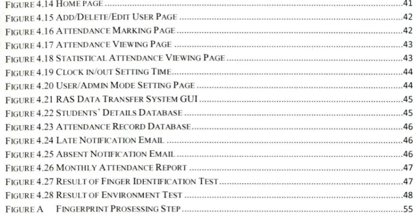
1.4.3 Technical Structure
5
Thumbprint PIC LCD
Scanne r M icrocontroller Dis play
Database
[image:20.501.123.420.60.221.2]User Interface
Figure 1.1: Block Diagram of the Overall System ' s Technical Structure
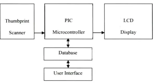
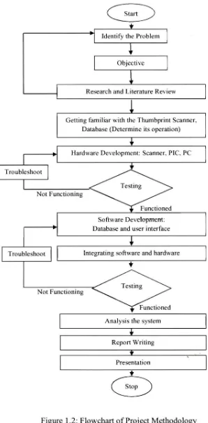
1.5 Project Planning
There are seven phases of work need to be done in order to complete this project. The first phase that needs to be settled first is problem statement identification. The problem faced by the previous approaches [3] included inaccuracy, time consuming, reliability, and security. The problem statements are reviewed throughout the project, to make sure the new system created able to solve the problem facing by the previous approaches [3].
Beside problem statements, the objectives of the project need be determined first in order to understand the purpose of the project and keep the project on the correct track. In this project, the objectives is to design and develop responsive attendance system based on thumb scanning for postgraduate students and improve the self-responsibility awareness among the postgraduate students.
After the problem statements and the objectives are identified. During Phase Three, the literature review was done to understand the overall systems that development. The researches indicated are:
1. Research on the thumbprint technology and its application.
6
Once the researches are done, Phase Four was continued by getting familiar with the components. The main components and software required in this project are Thumbprint Scanner, PIC Microcontroller, Structured Query Language (SQL) and Microsoft Visual Basic. These components and software need be fully understand first before it can be integrated together to fonn one system.
During Phase Five, the hardware part of the system was assembled. Then the project is followed with the development of the software part of the system which included the Database and the User Interface.
Troubleshoot
Identify the Problem
Objective
Research and Literature Review
Getting familiar with the Thumbprint Scanner, Database (Determine its operation)
Hardware Development: Scanner, PIC, PC
Not Functioning
Software Development: Database and user interface
Troubleshoot Integrating software and hardware
•
Not Functionjng
Analysis the system Report Writing
Presentation
t
8
Figure 1.2: Flowchart of Project Methodology
[image:22.501.83.381.63.669.2]CHAPTER2
LITERATURE REVIEW
2.1 Existing Attendance System
The several kind of attendance systems that are available in the market.
2.1.1 Manual Attendance Taking System
The Manual Attendance Taking System also known as Traditional Attendance
9
2.1.2 Time Clock Attendance Taking System
On 20th November 1888, the first time clock was invented [6]. Time clocks also known as punch clock or clock card machine or time stamp. The time clock is basically a clock with the function of recording the time on an inserted heavy paper card, which named as timesheet. It is a recording mechanism with typewheels [7]. First, user needs to insert the timesheet into the prepared slot and when the timesheet mo ve against the typewheels, the mechanism will activated [7] and the clock will print or stamp the date and time on the timesheet. The time clock increases the accuracy of the clock in and clock out time of the user. It is more efficient in recording the time. However, this time clock cause another problem arises, which is named as overstamping. This problem is when the recorded time is stamped over by another one. Besides, this system also leads to other problems [3] , which are the reliability of the system and the usages of paper card. Buddy punching is the act where one person clocks into the payroll system using another person ' s timesheet, creating it look as that a person, who did not actually come to work, is in fact worked for the full period of their shift [ 4]. Besides, the attendance of the employees is recorded on the timesheet; if the timesheet is stolen or misplace [8] then the employee will lost his or her attendance record.
2.1.3 Barcode Attendance Taking System