HEAT TRANSFER CHARACTERISTICS OF A HEAT EXCHANGER
JAMIATUL ADAWIAH BT AB. SIDEK
HEAT TRANSFER CHARACTERISTICS OF A HEAT EXCHANGER
JAMIATUL ADAWIAH BT AB. SIDEK
This report is submitted as a partial requirement for the completion of the Bachelor of Mechanical Engineering (Thermal Fluids) Degree Program
Faculty of Mechanical Engineering University of Technical Malaysia Melaka
ii SUPERVISOR VERIFICATION
I have read this thesis and in my opinion this report is sufficient in aspects of scope and quality for the award
Bachelor of Mechanical Engineering (Thermal fluids)
Signature :….………..
Name of Supervisor :………..
iii DECLARATION
“I hereby declare this report is a result from my own research except as cited in references”
Signature :……….
Author’s Name :………
iv DEDICATION
v ACKNOWLEDGEMENT
First and foremost, I would like to thank God for giving me this golden opportunity to work in such a wonderful project as a final year student. Secondly, a biggest appreciation to my brilliant supervisor Dr Yusoff Bin Sulaiman for valuable knowledge and advice throughout the journey of this project. He inspired me greatly in order to finish this task by showing some related study cases, design criteria and useful principles to be used in this project.
Besides, I would like to thank Universiti Teknikal Malaysia Melaka (UTeM) for giving me permission to do some research regarding my project in the laboratory as I needed. Also, many thanks to the faculty management team for their great cooperation. It was such a pleasure to deal with them.
vi ABSTRACT
vii ABSTRAK
viii
2.1 Background of heat exchanger 3-4
2.2 Automotive Heat exchanger 4-6
2.2.1 Heat transfer performance 7-10
2.2.2 Fins design 10-11
ix
CHAPTER 3 METHODOLOGY 13-25
3.1 Experimental study of radiator 15-17
3.2 Theoretical study of a radiator 17-18
3.3 CFD Analysis 18-19
3.4 Transparent tubes progress 19
3.5 Fabrication process 20-21
3.6 Material and apparatus 22
3.7 Experimental procedure of transparent 23
tubes
3.8 Experimental procedure of radiator 24
prototype
3.9 CFD Analysis procedure 25
CHAPTER 4 RESULT 26-28
5.5 Comparison with circular prototype 35-37
CHAPTER 6 CONCLUSION AND RECOMMENDATION 38-39
6.1 Conclusion 38
6.2 Recommendation 39
REFERENCES 40-41
x LIST OF TABLE
NO TITLE PAGE
3.1 Dimension of basic radiator as parameter 16
3.2 Workflow of designing a transparent tube radiator 19
3.3 Fabrication process of prototype of radiator 21
4.1 Time Taken for Left Inlet to Reach Reference Points 26
4.2 Time Taken for Centre Inlet to Reach Reference Points 27
4.3 Average Value of the Parameters 28
5.1 Result of Square Radiator Heat Transfer Performance 36
xi
2.5 Different outlet cold water temperature with hot water
xii LIST OF SYMBOL
CFD = Computational Fluid dynamics
ε = Effectiveness of a radiator
Lradiator = Radiator length
Hradiator = Radiator height
Wradiator = Radiator width
Wtube = Tube width
Htube = Tube height
Lfin = Fin length
Wfin = Fin width
Hfin = Fin height
xiii LIST OF APPENDICES
NO TITLE
A Gantt chart for PSM 1 and PSM 2
B Experimental raw data
C Flow distribution
D Sample calculation
1
CHAPTER 1
INTRODUCTION
1.1 BACKGROUND OF STUDY
Automotive car radiator is a heat exchanger and its basic principle is to transfer heat between one medium to another. Heat exchanger is used to perform this kind of work from one side of a fluid to another without mixing them. It maximizes the use of surface area in order to get a higher rate of heat transfer between the systems. Nowadays, automotive radiator has some problems to deal with and the major problem is high demand in terms of enhancement of heat dissipation especially for advanced engines that are built in compact size. Most of the energy produced by the engine is lost due to combustion and it causes the engine to experience overheating. Overheating will lead to failure of the system such as wear formation between engine, metal damage of inner parts and inefficient lubricating process. A new generation of automotive heat exchanger must be able to perform high level of heat transfer while maintaining its compact and advanced design.
2
1.2 PROBLEM STATEMENT
The uncertain flow characteristic of the fluids sometimes caused an imperfect flow of the fluids through all the tubes of the square automotive radiator. Heat transfer performance is not efficient as the fluids flow does not completely touch the surface area of the tubes or fins.
1.3 OBJECTIVES
To achieve a successful goal of this project, several objectives are made to guide the flow of the study:
a) To design and fabricate an experimental and prototype of automotive radiator.
b) To investigate heat transfer performance of heat exchanger unit.
c) To study the experimental and theoretical result of heat performance.
1.4 SCOPE OF WORK
3
CHAPTER 2
LITERATURE REVIEW
2.1 BACKGROUND OF HEAT EXCHANGER
A heat exchanger is a vital component in certain system and its purpose is to transfer thermal energy of solid and fluid surface or between fluid and particulates of solid surface involving two or more medium in temperature varies condition that in thermal contact. The medium usually fluids, can be mixtures or single compound. Basic principle of heat exchanger involving process of heating or cooling of concerned fluid stream, evaporation or condensation process of the fluid components and even heat gain or heat rejection of the system.
4
However, this regenerator type is familiar with leakage issue and improper flow of fluid from one stream to another. Heat exchanger can be classified based on its transfer process, construction, surface size, fluids amount, functions and mechanism of the heat transfer (Said Moataz, 2009).
2.2 AUTOMOTIVE HEAT EXCHANGER
Automotive heat exchanger or car radiator operates similarly with another heat exchanger to make sure the engine is cool to function at its best performance. Basically, fluid is pumped by the internal combustion engine, and then the fluid is flows into the radiator and meets numerous numbers of tubes which attached with large amount of fins. The purpose of fins is to increase the surface area in order to enhance the cooling effect of the air flow through the radiator. Furthermore, the movement of a car, together with radiator fan forces air to flow through the fins and the surrounding tubes of the radiator. This phenomenon helps to eliminate heat from the water flowing process through all the fins and tubes and dissipate it to the surrounding air (Carl M, Guy D).
5
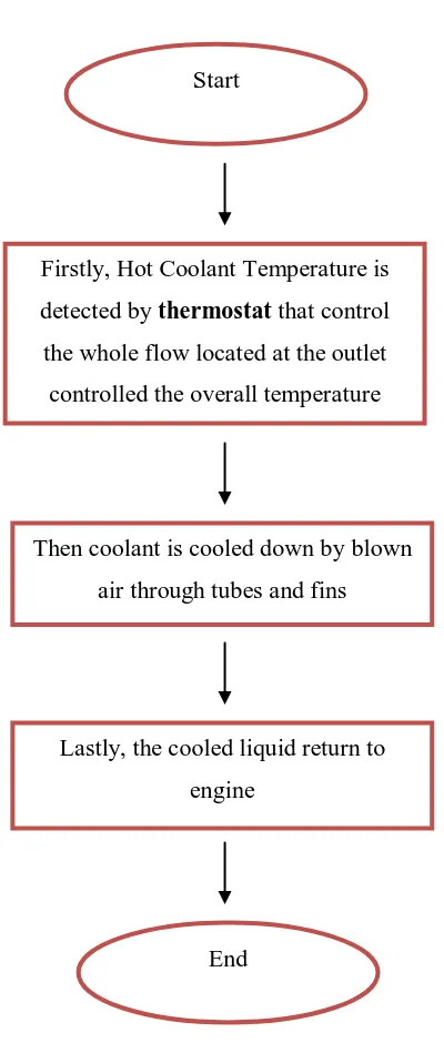
Figure 2.1: Flow chart of cooling process Start
Firstly, Hot Coolant Temperature is
detected by thermostat that control
the whole flow located at the outlet
controlled the overall temperature
Then coolant is cooled down by blown
air through tubes and fins
Lastly, the cooled liquid return to
engine
6
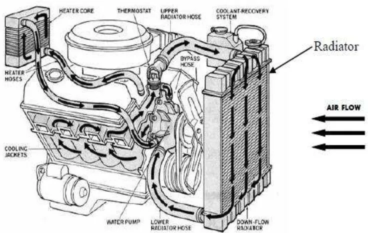
Figure 2.2: Automobile Engine Cooling System (Scott Janowiak, 2007)
In addition, most common radiator as Figure 2.2 which made from aluminium base and utilizes heat exchanger design of cross flow type. The main reason of using aluminium instead of others is because aluminium is much lighter and cheaper. Besides, medium involved in radiator are air and coolant that made up of 50% of mixed water and the remaining half is ethylene glycol. General purpose of presence of air is to get rid of heat from the coolant and later causes the coolant to end up at lower temperature at the exit compare to its entrance temperature. The criteria for heat transfer of current radiators are 140 kW of heat and 95oC of inlet temperature of basic radiator size. However, this benchmark may be varies depending on the model of a radiator (Scott Janowiak, 2007).
7
2.2.1 Heat Transfer Performance
Heat transfer occurs when there is difference in temperature between two or more channels of a medium. It involves transit process of thermal energy due to personal space temperature difference (Incopera, F.P).
As a rule, heat transfer process is divided into three physical mechanism conduction, convection and radiation. All of these three mechanisms solely depend on temperature difference. Conduction is a process of heat transfer from one region to another by short contact range of a molecular scale. Conversely, convection is a heat transfer mechanism of both process of conduction and fluid mixing. While, radiation is energy emission process by any bodies in terms of electromagnetic wave above the absolute zero temperature condition (Avallone, E.A).
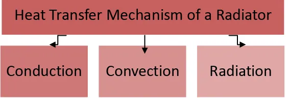
Obviously, the heat transfer mechanisms involved in coolant are conduction and convection as these two mechanisms describe the cooling effect process of air flow inside the radiator and its link from the core of radiator to the surrounding heat generated. In essence, in radiator world three kinds of heat transfer mechanism take place, as conduction occurred between the metal surfaces and the fins surfaces. Convection occurs between fins surfaces and ambient temperature of surrounding. Last one, radiation happens when there is a source of heat in this case, a heat from the engine. Figure 2.3 presents the heat transfer mechanism of a radiator
Figure 2.3: Heat transfer mechanism of a radiator
Heat Transfer Mechanism of a Radiator
8
Moreover, automotive heat exchangers have some certain criteria that will oppose large effect to the heat transfer of a cooling system for instance, temperature differential, supply heat load and radiator design. Temperature differential is the largest temperature difference recorded between two points at instant specified test volume. Temperature differential between cooling air and basic radiator core temperature is the process that initiates the cooling effect or heat transfer process through the cool air flow medium from the radiator and coolant. Heat is originated from the internal combustion and later heat is created up to predestine operating temperature and coolant starts to flow and passes the whole radiator as the thermostat leave to open.
At the beginning, engine and coolant take in heat through conduction and convection and continue until it surpasses the cooling air flow temperature. At this stage, heat transfer process from the hot region to the cooling air commences. Coolant temperature keep rising until it meets a stage of temperature differential of the core radiator and cooling air is huge enough to deliver the whole heat load to cooling air; at this moment steady state level is achieved. Of all cooling system the heat transfer characteristic is regulate by heat load to the cooling system value. Heedless of either poorly or perfectly designed radiator is used, the heat load also known as the heat rejection of a cooling system is sent to the cooling system by the automotive heat exchanger. The main reason cooling system analysis is hard is because of quantifying procedure of the radiator performance the result of heat rejection is same whether it is done by a good or poor radiator. For difference types of radiator geometry, the different between these two good and poor radiators is a good radiator inlet temperature manages to stabilize itself at lower temperature of the core performance. Therefore, overheating phenomenon of the coolant boiling can be prevented as in Figure 2.4. Besides, it has been proven that design of radiator core will not affect much on heat load capabilities handling but it will help to get a lower
steady state achievement. In average cars, most of them will have 88oC temperature
9
i. Coolant flow rate
ii. Cooling air flow
iii. Radiator face area
Figure 2.4: Heat Load Performance of Radiators (Crook, R.F. 2007)
10
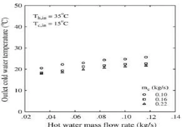
Figure 2.5: Different outlet cold water temperature with hot water mass flow rate in helical coiled finned heat exchanger (International Communications in
Heat and Mass Transfer, 2007)
In addition, a wide range of Reynolds number can also affect the heat transfer performance. A research has been made where large range of Reynolds number from 30 to 30 000 Newtonian fluids in two different configurations a chaotic and helical heat exchanger. However, the number of the heat exchanger curved and surface area are kept constant within these two types. The results shows at lower value of Reynolds number, heat transfer rate is almost similar to the normal heat exchanger but it increase at chaotic design without any requirement of extra energy. The utmost heat transfer coefficient is at 250 of Reynolds number at chaotic type is recorded (C. Chagny, 1999)
2.2.2 Fins Design


