‘I admit that I have read the whole of this report and in my opinion this report is fully in scope and high quality for conferment of Bachelor Degree in Mechanical Engineering
(Thermal-Fluid)’
Signature :………
Supervisor’s name :………
PARAMETER STUDY ON HEAT EXCHANGER
MASITA BINTI MOHD BARI
This report is to fulfill a partial of requirement conferment of Bachelor Degree in Mechanical Engineering (Thermal-Fluid)
Faculty of Mechanical Engineering Universiti Teknikal Malaysia Melaka
“I admit that I have made this report on my own except the summary and sentences whish is explained from the references”
Signature :………
Author’s Name :………
iii
ACKNOWLEDGEMENT
I would like to express a warm gratitude to everyone who involved directly or indirectly during accomplishment this report. Heartfelt thankfulness goes to Mdm. Fatimah Az-Zahrah bt Mohd Sa’at for guiding in order to complete this report. Because of her guiding I have accomplish this report from beginning and complete promptly. Also, I would like to thankful to personnel who lecturer from Department of Mechanical Engineering because have continuously, encouraging and guiding me and also gave me supports and advices.
iv
ABSTRACT
v
ABSTRAK
vi
TABLE OF CONTENTS
CHAPTER CONTENT PAGE
TESTIMONIAL ii
AKCKNOWLEDGMENT iii
ABSTRACT iv
ABSTRAK v
TABLE OF CONTENTS vi
LIST OF TABLE ix
LIST OF FIGURE x
LIST OF SYMBOL xiii
APPENDICES xiv
CHAPTER 1 INTRODUCTION
1.1 Background 1
1.2 Problem Definition 3
1.3 Objective 4
1.4 Scope 4
CHAPTER 2 LITERATURE REVIEW
2.1 Radiator 5
2.2 Parameter Commonly Involved in Heat Exchanger 11
Analysis
2.2.1 Air and Coolant Mass Flow
11 2.2.2 Air Inlet Temperature
vii 2.2.3 Coolant Fluid
15
2.2.4 Fin Pitch 15
2.2.5 Louver Angle 18
CHAPTER CONTENT PAGE
2.2.6 Louver Pitch 19
2.2.7 Coolant Flow Lay-out 19
2.3 Numerical Analysis of Radiator Heat Exchanger 21
CHAPTER 3 METHODOLOGY
3.1 Introduction to Numerical Software 30
3.2 Flow Chart for Project 32
3.3 Mathematical Equation 33
3.4 Physical Domain 36
3.4.1 3-Dimensional Computational Domain 36
3.4.2 Air Flow 37
3.4.3 Fins 38
3.4.4 Tubes 38
3.4.5 Liquid/ Coolant 39
3.5 Boundary Condition 39
3.6 External CAD Drawing 40
3.6.1 Basic Concept of SolidWork 40
3.6.2 Sketching Concepts 40
3.6.3 Feature- based Models 41
3.6.4 Cutting the Features 44
3.7 The ANSYS Workbench 44
3.7.1 Design Modeler 45
3.7.2 Procedure in ANSYS Workbench 45
3.8 CFX-Mesh 47
viii
3.9 CFX-Pre 51
3.10 Obtaining a Solution Using CFX Solver
Manager 55
3.11 Viewing Result in CFX Post 56
3.11.1 Creating a Streamline 56
3.11.2 Adding Contour 56
CHAPTER CONTENT PAGE
CHAPTER 4 RESULTS AND DISCUSSIONS 58
4.1 Air mass flow influence 63
4.2 Air inlet temperature influence 65
CHAPTER 5 CONCLUSION AND RECOMMENDATIONS 69
REFERENCES 71
1) Journal 71
2) Books 72
BIBLIOGRAPHY 73
ix
LIST OF TABLE
NO: TITLE PAGE
1 Baseline working conditions for automobile radiator 39 (Source: Oliet et al. (2007))
2 The setting domain in CFX-Pre 52
x
LIST OF FIGURE
NO: TITLE PAGE
2.1 Radiator and fin pitch (Source: Carluccio et al. (2005)) 7
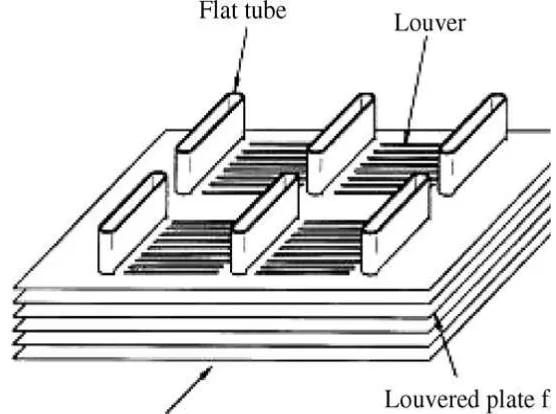
2.2 Flat-sided tube and louvered plate fin heat exchanger 8 (Source: Malapure et al. (2007))
2.3 Air and coolant mass flow influence on the thermal and 12 fluid-dynamic performance of the automotive radiator
(Source: Oliet et al. (2007))
2.4 Air inlet temperature influence on the thermal and 14 fluid-dynamic performance of studied radiator
(Source: Oliet et al. (2007))
xi 2.6 Fin spacing influence on thermal and fluid-dynamic
17
behaviour of heat exchanger (Source: Oliet et al. (2007))
2.7 Performance maps obtained for a parametric study fin 22
pitch, Fp, in this case. On the left, heat transfer depends on air and coolant flow rates. At the right, overall enhancement versus air and coolant flow regime (Source: Oliet et al. (2007))
2.8 Schematization for the first run 23
(Source: Carluccio et al. (2005))
2.9 Shell side surface mesh (near inlet plane). 24 (Source: Witry et al. (2005))
2.10 Tube side surface mesh (near inlet). 24
(Source: Witry et al. (2005))
2.11 The simulated set up (Source: Witry et al. (2005)) 25
2.12 Dimensional detail with thickness 0.05mm,, tube size 27 16 x 2mm, longitudinal tube pitch 20mm and length of
fin in airflow direction 21.6mm for single row and 41.6mm for double row (Source: Malapure et al. (2007))
2.13 3D computational domain and boundary condition 29
(Source: Perrotin and Clodic (2004)).
3.1 3D computational domain (Source: Oliet et al. (2007)) 37
3.2 The 3D geometry of louvered fin and half tube 43
xii
3.4 Side-view of the geometry 43
3.5 After importing the geometry to the ANSYS Workbench
and be frozen 46
3.6 Add material at tube and fin for the coolant and air
flowing through it 46
3.7 After generating meshing 51
3.8 The meshing structure of the surface 51
3.9 The direction inlet and outlet of flow for coolant and air 54 3.10 The example of the solver result after run is completed 55
4.1 Pressure drop along the air flow direction for Air inlet
temperature 40°C at air flow rate 0.4 kg/s 59
4.2 Temperature drop for air inlet at 40 ° C at air flow rate
0.4 kg/s 59
4.3 Velocity along fin for air inlet at 40 ° C at air flow rate
0.4 kg/s 60
4.4 Temperature drop for air mass flow rate at 0.08 kg/s and
coolant mass flow rate at 0.69 kg/s 60
4.5 Pressure drop for air mass flow rate at 0.08 kg/s and coolant
mass flow rate 0.69 kg/s 61
4.6 Velocity along fin for air mass flow rate at 0.08 kg/s and
coolant mass flow rate 0.69 kg/s 61
xiii
flow influence 63
4.8 Graph difference temperature versus air flow rate for air
mass flow influence 64
4.9 Graph difference temperature versus air inlet temperature
for air inlet influence 66
4.10 Graph air pressure drop versus air inlet temperature at air
mass flow rate 0.08 kg/s 67
4.11 Graph air pressure drop versus air inlet temperature for air
mass flow rate 0.4 kg/s 67
LIST OF SYMBOL
A = Area, m2
p
C = constant pressure specific heat, (kJ/kg.K) α = Louver angle ( ˚ )
f = friction factor Fp = fin pitch (mm)
xiv
m = mass flow rate (kg/s) Nu = Nusselt number
ρ = density (kg/s) P
∆ = pressure drop (Pa) .
Q = heat transfer rate or cooling capacity (kW)
R = radius (m)
Re = Reynolds number Tp = Transverse pitch (mm) S = strength (N/m2)
U & V = velocity (m/s) µ = viscosity (ms/kg)
.
V = volume flow rate (m3/s)
APPENDICES
NO: TITLE PAGE
A. Part of Geometry Radiator and Geometry Description
under Study 75
B. Part of The Geometry that Involved in This Study 76
xv
D. Project Planning for PSM 1 83
CHAPTER 1
Introduction
1.1 Background
A heat exchanger is a specialized device that assists in the transfer of heat from
one fluid to the other. When a fluid is used to transfer heat, the fluid could be a liquid, such as
water or oil, or could be moving air. This heat will transfer through the metal surface, while
convection is used to transfer heat through the liquid. In some cases, a solid wall may
separate the fluids and prevent them from mixing. In other designs, the fluids may be in
direct contact with each other. In the most efficient heat exchangers, the surface area of
the wall between the fluids is maximized while at once minimizing the fluid flow
resistance. Fins or corrugations are sometimes used with the wall in order to increase the
surface area and to induce turbulence.
There are various types of heat exchangers which are air-to-liquid cooling,
liquid-to-air cooling, liquid-to-liquid cooling, or air-to-air cooling. With air-to-liquid
cooling, heat is transferred from the air to a liquid. One example of air-to-liquid cooling
is cabinet cooling. With liquid-to-air cooling, the heat is transferred from the liquid to
the air. This type of cooling is generally used to cool process fluids. Liquid-to-liquid
cooling is also used to cool process fluids, but the heat is removed by another liquid
instead of by air. Lastly, with air-to-air cooling, heat is transferred from one air or gas
stream to another.
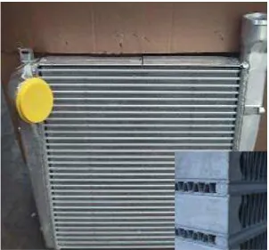
For oil cooler flat tube heat exchangers have tubes and fin; however, the tubes
are flat instead of round. This helps to minimize pressure drop when oil or ethylene
glycol is used as the coolant. The surface area of the flat tubes is also much greater than
the surface area of the tubes in a tube and fin heat exchanger. The additional surface area
of the tubes in an oil cooler flat tube heat exchanger maximizes heat transfer when poor
heat transfer fluids like oil or ethylene glycol are used. These oil cooler heat exchangers
consist of fin, flat tubes, a welded header with inlets and outlets, and plates, including an
optional fan plate.
Another type of heat exchanger is a plate-fin heat exchanger, which can provide
air-to-air, air-to-liquid, liquid-to-air, or liquid-to-liquid cooling. Plate-fin heat
exchangers consist of finned chambers separated by flat plates and are circuited in
alternating hot and cold fluid passages. Heat is transferred via fins in the passageways,
through the separator plate, and into the cold fluid via the separator plate, and into the
cold fluid via fin once again. The heat exchanger also has manifold ducting, mounting
brackets, and a frame. Liquid-to-liquid brazed plate heat exchangers also have plates, but
with a herringbone pattern of groves, stacked in alternating directions. This forms
separate flow channels for two liquid streams so that the two fluids are never in direct
contact. The heat exchanger plates are brazed together at the edges and at a matrix of
contact points between sheets. The liquid-to-liquid heat exchanger can be compared to a
shell and tube heat exchanger, which is used in similar applications.
The thermal performance of heat exchanger technologies can vary quite a bit, so
when selecting a heat exchanger it's important to understand what performance is needed
as well as what fluids are available for removal of heat. It's also important to evaluate the
entire system when deciding on a heat exchanger, as there are a number of
considerations including flow rate, pressure drop, materials compatibility, and more.
Common appliances containing a heat exchanger include air conditioners,
refrigerators, and space heaters. Heat exchangers are also used in chemical processing
and power production. The most well known type of heat exchanger is a car radiator,
radiator. In radiator, a solution of water and ethylene glycol, will transfer heat from the
engine to the radiator and then from the radiator to the ambient air flowing through it.
The solution of water and ethylene glycol known as antifreeze. This process helps to
keep a car's engine from overheating. Similarly, heat exchangers are designed to remove
excess heat from aircraft engines, optics, x-ray tubes, lasers, power supplies, military
equipment, and many other types of equipment that require cooling beyond what
air-cooled heat sinks can provide.
1.2 Problem Definition
The automotive manufacturing is endlessly involved in a well-built
competitive career to attain the best automobile design in multiple aspects
(performance, fuel consumption, aesthetic, safety, etc.). The air-cooled heat
exchanger creates in an automotive (radiator, AC-alternative current, condenser
and evaporator, charge air cooler, etc.) cover a significant function in its weight
and also in the design of its front-end module, which also has a strong impact on
an automobile aerodynamic behavior. For these challenges, an optimization
process is compulsory to obtain the best design negotiation between
performance, size/shape, and weight. The approach of this study is oriented to
computationally characterize the full heat exchanger including air and liquid side
influences on overall performance which are cooling capacity and pressure drop.
For the case of automobile radiator, the dominant thermal resistance generally
occurs on the airside which is the reduction in the air-side thermal resistance will
improve the heat transfer performance of the heat exchanger. The louvered fin
1.3 Objective:
The aim of this study is to characterize the heat exchanger influences on overall
performance in radiator.
1.4 Scope:
The approach of this study is oriented to computationally characterize the full
heat exchanger including air and liquid side influences on overall performance which are
cooling capacity and pressure drop. This study is structured in a first part where the
modeling technique and formulation are briefly summarized. The numerical analysis
with complex mathematical model becomes the great solution to give detailed
predictions on the effects that the heat transfer enhancing techniques and design which
can have on the devices performance.
This study is limited:
i) To identify parameter that influences heat exchanger performance. This study is
focusing on the influence of working condition on both fluids which are air and
coolant mass flows air inlet temperature.
ii) To computationally simulate the effect of those parameter to heat exchanger
performance. In this study, the CFX. Codes will be used.
CHAPTER 2
LITERATURE REVIEW
2.1 Introduction to Radiator
In recent years a growing and intense attention has been turned to the study of
concept compact heat exchanger which is application in automotive radiator. Since it
represent a good solution in terms of dimension and efficiency for industrial application
compared to the traditional approach. In automotive applications the use of compact heat
exchanger helps in reaching high levels of temperature and pressure within severe
constraints of dimensions. Manufacturing compact heat exchanger is worth as heat can
be transferred using devices of limited dimensions (Carluccio et al.2005). According to
Dittus et al. (1985), heat to be dissipated from water-cooled internal combustion engines
is usually transferred to the atmosphere by means of devices commonly called radiator.
Radiator is a component that control engine temperature in automobile where liquid to
be cooled by air. Air is a medium to transfer heat to the surrounding. In radiator, cooling
is made by means of air pushed to the heat exchanger by an external fan. Cihat and
Feridum-Ozguc.A (2006) found that radiator is hotter than surrounding, where heat will
transfer to the air and water exits at lower temperature. It was equipped with convection
fins to improve heat output which is mostly by natural convection. The contribution of
radiative heat transfer to the total heat transfer is smaller than the natural convection heat
transfer. As found by Olsson and Sunden (1996), the medium conveying heat to radiator
air. Liquid will be flown in tubes while the air flow in channel set up by fin surfaces.
The thermal resistance on the air is larger than on the liquid side. Besides, the previous
study by Dittus and Boelter (1985) found that heat carried from warm water to colder
tube by two processes which are convection and conduction. Inside the tube, fluid flow
mostly turbulent. In the region of turbulent flow, most of the heat is transferred from the
liquid to the tube wall by forced convection. As a consequence of the low thermal
conductivity of fluids, very little heat is transferred from the center of the stream to the
tube wall by conduction. In the viscous flow region, heat will transfer from interior
stream to tube wall by conduction.
In order to improve the heat transfer surfaces applied the turbulence flow (Olsson
and Sunden (1996)). The fluid flow is turbulent, unless the tube diameter is very small
(Dittus and Boelter (1985)). The tubes dimension length can not be used very long
because temperature different between bulk of fluid and wall at outlet measure with
sufficient accuracy. The inlet tubes suspended with no nearby surface and at atmospheric
pressure and no effect of distortion due to low pressure in tubes. Water flowing around
the tube in cross flow with speed 1m/s and two-dimensional contraction placed upstream
of tube to make water flow uniform. The heat transfer coefficient at the outer tube is
larger than the inside wall. For the higher velocities, the maximum heat transfer rate
appears at higher radius of tube. The variations of maximum heat transfer rate and
optimum dimension as a function of radiator volume fraction for three different
environment temperatures. The increase of radiator volume fraction increases the
maximum heat transfer rate and optimum tube diameter (Olsson and Sunden, (1996)).
For this study, the flow inside the tube was assumed turbulent flow. The variations of
maximum heat transfer rate and optimum tube radius as a function of radiator volume
fraction for three different ambient fluid temperatures. Cihat and Feridum-Ozguc (2006)
found that the maximum heat transfer rate depends on ambient temperature but the
corresponding optimum tube radius does not depend on this parameter.
Figure 2.1: Radiator and fin pitch (Source: Carluccio et al. (2005))
In addition, for the smooth tube exhibits the lowest friction factor.All the other
tubes which are rib-roughened, dimpled and offset strip fin tubes have larger friction
factors, f, at both laminar and turbulent. All the enhanced tubes have better heat transfer
performance than the smooth tube. The dimpled tubes show a slightly better
performance than the offset strip fin tube, while the smooth tube takes the lowest
position. For the offset strip fin tubes, boundary layers are developed periodically I-short
channel formed by the fins (Olsson and Sunden (1996)).
The rate heat from water to its air retarded by resistance on water side of tube
surface, thermal resistance and resistance on air side of tube (Dittus and Boelter (1985)).
Besides, the thermal resistance outside the tubes is less than the inside of tube so assume
it negligible. The thermal resistance on the air is larger than on the liquid side. Flat tubes
on liquid have small dimension to enhance heat transfer processes. For higher
(1996)). Besides, the study by Malapure et al. (2007) found that the temperature of the
fin decreases with the distance from the tube surface because of the thermal resistance of
fin and carried away by the cooling air. Analysis by Dittus and Boelter (1985) on heat
transfer in tubular radiator indicates that a large part of the total resistance to heat flow
because the relatively low film transfer factors on the air side of the tubes. So that, any
attempt to increase the overall heat transfer factor in radiator should begin by improving
the film transfer factor on the air side of the tube. Some improvements might be also
made by decreasing the film resistance on the liquid side of the tubes, although the total
gain will be slight unless the air film transfer factor increases materially at the same
[image:24.612.205.483.278.485.2]time.
Figure 2.2: Flat-sided tube and louvered plate fin heat exchanger
(Source: Malapure et al. (2007))
While, the tube length influence on the Nusselt number, Nu is more pronounced
in laminar flow than in turbulent flow. The difference in performance between the
enhanced tubes will be decreased (Olsson and Sunden (1996)). Besides, the decreasing
values of Nusselt number, Nu, with the distance from the entrance together with the
decrease of the temperature difference between wall and air. The Nusselt number, Nu,
with reference to the flow direction will be decreased of local heat transfer convective
coefficient, h, going from the entrance to the exit and makes possible to understand the