2
DESIGN AND IMPLEMENTATION OF OFTHOGONAL FREQUENCY DIVISION MULTIPLEXING TRANSMITER
SITI SUZANA BINTI AHMAD KAMRI
This report is submitted in partial fulfillment of requirement for the award of Bachelor of Electronic Engineering (Electronic Telecommunication) With Honours
Faculty of Electronic and Computer Engineering Universiti Teknikal Malaysia Melaka
3
UNIVERSITI TEKNIKAL MALAYSIA MELAKA
FAKULTI KEJURUTERAAN ELEKTRONIK DAN KEJURUTERAAN KOMPUTER
BORANG PENGESAHAN STATUS LAPORAN
PROJEK SARJANA MUDA II
Tajuk Projek : DESIGN AND IMPLEMENTATION OF ORTHOGONAL FREQUENCY MULTIPLEXING TRANSMITER
Sesi Pengajian : 2009/2010
Saya SITI SUZANA BINTI AHMAD KAMRI
mengaku membenarkan Laporan Projek Sarjana Muda ini disimpan di Perpustakaan dengan syarat-syarat kegunaan seperti berikut:
1. Laporan adalah hakmilik Universiti Teknikal Malaysia Melaka.
2. Perpustakaan dibenarkan membuat salinan untuk tujuan pengajian sahaja.
3. Perpustakaan dibenarkan membuat salinan laporan ini sebagai bahan pertukaran antara institusi pengajian tinggi.
4. Sila tandakan ( √ ) :
SULIT*
(Mengandungi maklumat yang berdarjah keselamatan atau kepentingan Malaysia seperti yang termaktub di dalam AKTA RAHSIA RASMI 1972)
TERHAD* (Mengandungi maklumat terhad yang telah ditentukan oleh organisasi/badan di mana penyelidikan dijalankan)
TIDAK TERHAD
Disahkan oleh:
__________________________ ___________________________________
(TANDATANGAN PENULIS) (COP DAN TANDATANGAN PENYELIA)
Alamat Tetap:
NO 112,BLOK 5, Felda Raja Alias 2,
72120 Bandar Seri Jempol, N.Sembilan.
Tarikh: ……….. Tarikh: ………..
4
“I hereby declare that this report is result of my own effort except for works that have
been cited clearly in the references.”
Signature : ……….
Author : Siti Suzana binti Ahmad Kamri
Date : ……….
5
“I hereby declare that I have read this report and in my opinion this report is sufficient in
terms of scope and quality for the award of Bachelor of Electronic Engineering
(Electronic Telecommunucation) with Honours”
Signature : ………..
Supervisor‟s Name : PM MUHAMMAD SYAHRIR BIN JOHAL
Date : ………..
6
To my beloved late mother, siblings, lecturers and friends.
7
ACKNOWLEDGEMENT
Thanks to Allah because for completing this “Projek Sarjana Muda”
successfully. I also appreciate all advice and support from my supervisor, PM Muhamad Syahrir Bin Johal , those who are very patient in guiding me until I finished. To my parents, thank you very much because both of you always with me through difficulty and good times. Thank you to my fellow friends for giving me an encouragement and pray for a great success. Additionally, to those whom their names are not mentioned
here that have help me directly or indirectly, there is no such meaningful word than…
Thank you so much. May Allah always be with you. Last but not least, to the Faculty of Electronic and Computer Engineering (FKEKK), because giving me chance to study and complete my project as part of the Bachelor program in Universiti Teknikal Malaysia Melaka (UTEM).
8
ABSTRACT
Orthogonal Frequency Division Multiplexing (OFDM) is a multi carrier modulation technique. OFDM provides high bandwidth efficiency because the carriers are orthogonal to each others and multiple carriers share the data among themselves. The main advantage of this transmission technique is their robustness to channel fading in wireless communication environment due to its resistance to inter-symbol interference (ISI). The main objective of this project is to design and implement a base band OFDM transmitter by using simulation in Matlab. This project focuses on the core processing block of an OFDM system, which are the Inverse Fast Fourier Transform (IFFT) block. The IFFT is analyzed in detail to produce a solution that is suitable for DSP board implementation.
9
ABSTRAK
„Orthogonal Frequency Division Multiplexing‟ (OFDM) adalah sebuah teknik
modulasi multi pembawa. OFDM mempunyai kecekapan jalur lebar yang tinggi kerana pembawa yang orthogonal antara satu sama lain dan beberapa pembawa berkongsi data di antara mereka sendiri. Kelebihan dari teknik penghantaran ini adalah ketahanan mereka untuk saluran penurunan dalam lingkungan komunikasi tanpa wayar kerana perlawanannya terhadap „Inter-symbol Interference‟ (ISI). Tujuan utama dari projek ini adalah untuk merancang dan mengimplementasikan sebuah dasar pemancar OFDM dengan menggunakan simulasi di Matlab. Projek ini tertumpu pada pemprosesan blok sistem OFDM, yang merupakan Inverse Fast Fourier Transform (IFFT) blok teras. IFFT dianalisis secara terperinci untuk menghasilkan penyelesaian yang sesuai untuk pelaksanaan di DSP board.
10
CONTENT
CHAPTER CONTENT PAGE
TITLE
CONFESSION iii
ACKNOWDGEMENT vi
ABSTRACT vii
ABSTRAK viii
CONTENTS x
LIST OF TABLE xii
LIST OF FIGURE xiii
LIST OF ABBREVIATIONS xiv
I INTRODUCTION 1.1 Introduction 1
1.2 Digital Communication System 1
1.3 Project Summary 2
1.4 Objectives 3
1.5 Project Background 3
1.6 Problem Statements 4
1.7 Scope of Work 5
11 II LITERATURE REVIEW
2.1 Wireless Communications 6
2.2 Orthogonality 7
2.3 Orthogonal Frequency Divison Multiplexing (OFDM) 8 2.4 Intersymbol Interference 11
2.5 Digital Video Broadcasting –Terrestrial 13
2.6 OFDM Transmisson 15
III METHODOLOGY 3.1 Introduction 18
3.2 Project Flow 19
3.3 Software Development 21
3.3.1 Matlab Software 21
3.4 Hardware Development 22
3.4.1 DSP Processor Board 22
3.4.2 Characteristic of DSP 23
3.4.3 Architecture 23
3.4.4 Program Flow 24
3.4.5 Data Operation 25
3.4.6 Instruction Sets 25
IV SIMULTION AND RESULT 4.1 Introduction 26
12 4.2 Simulation and Analysis 27
4.3 Simulink 36
V CONCLUSION AND RECOMMENDATION
5.1 Conclusion 38 5.2 Recommendation 39
REFERENCE 40
13
LIST OF TABLES
NO TITLE PAGE
2.6.1 Numerical values for the OFDM parameters for the 2k mode 16
4.2.1 Time response of signal carrier at (B) 28
4.2.2 Frequency response of signal carrier at (B) 29
4.2.3 Time response of signal U at (C) 31
4.2.4 Frequency response of signal U at (C) 31
4.2.5 Time response of signal UOFT at (D) 32
4.2.6 Frequency response of signal UOFT at (D) 33
4.2.7 Time response of signal s(t) at (E) 34
14
LIST OF FIGURES
NO TITLE PAGE
1.2.1 Digital Communication Systems 1
1.5.1 OFDM Transmitter 3
2.2.1 Orthogonal 7
2.4.1 Multipath and intersymbol interference 11
2.4.2 OFDM and OFDMA mitigate interference by breaking the signal 12
into multiple subcarriers 2.5.1 Scheme of a DVB-T transmission system 14
3.3.1.1 Matlab 7.8.0 (R2009a) version 21
3.3.1.2 Command Window in Matlab 21
3.4.1.1 Interface of DSP board processor (Top) 22
3.4.1.2 Interface of DSP board processor (Side) 22
4.2.1 Block Diagram of OFDM symbol generation simulation 27
4.2.2 Pulse shape of the signal g(t) 30
4.2.3 D/A filter response of the signal 30
4.3.1 OFDM System by Simulink 36
4.3.2 The OFDM Transmission by Simulink 36
15
LIST OF ABBREVIATIONS
OFDM - Orthogonal Frequency Division Multiplexing ISI - Intersymbol Interference
IFFT - Inverse Fast Fourier Transform
DVB-T - Digital Video Broadscasting- Terestrial DSP - Digital Signal Processing
ADC - Analogue to Digital Converter AWGN - Additive White Gaussian Noise FDM - Frequency Division Multiplexing
16
CHAPTER 1
1.1 INTRODUCTION
This chapter 1 is contains about the introduction of the project where it involve of the objectives, problem statements, scope, methodology, and report structure.
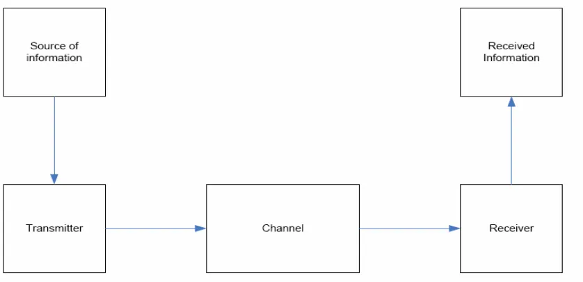
1.2 Digital Communication System Structure
[image:15.612.125.544.480.683.2]A digital communication system involves the transmission of information in digital form from one point to another point as shown in Figure 1.1
17
Regardless of the form of communication method, the three basic elements in a communication system consist of transmitter, channel and receiver. The source of information is the messages that are to be transmitted to the other end in the receiver. A transmitter can consist of source encoder, channel encoder and modulation. Source encoder employed an efficient representation of the information such that resources can be conserved. A channel encoder may include error detection and correction code. The aim is to increase the redundancy in the data to improve the reliability of transmission. A modulation process convert the base band signal into band pass signal before transmission. During transmission, the signal experiences impairment which attenuates the signals amplitude and distort signals phase. Also, the signals transmitting through a channel also impaired by noise, which is assumed to be Gaussian distributed component. In the receiver end, the reversed order of the steps in the transmitter is performed. Ideally, the same information must be decoded in the receiving end.
1.3 Project Summary
This project will focus on Orthogonal Frequency Division Multiplexing (OFDM) research, simulation, and implementation of its transmitter. OFDM is a modulation technique especially suitable for wireless communication due to its resistance to inter-symbol interference (ISI). After researching OFDM, simulation in MATLAB will be completed. The main part of this project will be using the simulation results as a guide to implement OFDM on a DSP board. The MATLAB code will need to be converted to either C or Simulink. This makes the code compatible with the software tool for the particular DSP board. To test the DSP code, the input and output vectors of the MATLAB simulation and DSP implementation will be verified to correspond.
18 1.4 Objectives
The main objective for this project is to design an OFDM transmitter by using Matlab Software. OFDM is a modulation technique especially suitable for wireless communication due to its resistance to inter-symbol interference (ISI).
The second objective is that higher subcarriers will produce better performance. The range carriers for 2K modes are 853-1705 subcarriers. This mode is intended for mobile reception of standard definition DTV (mobile TV).
The third objective is to implement an OFDM transmitter design on DSP board. The MATLAB code will need to be converted to either C or Simulink.
1.5 Project Background
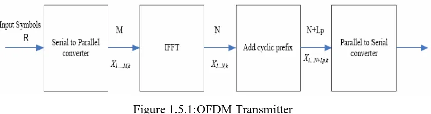
[image:17.612.120.540.522.634.2]This project will focus on Orthogonal Frequency Division Multiplexing (OFDM) research and simulation. OFDM is especially suitable for high-speed communication due to its resistance to ISI. As communication systems increase their information transfer speed, the time for each transmission necessarily becomes shorter. Since the delay time caused by multipath remains constant, ISI becomes a limitation in high-data-rate communication Figure 1.2 show a detailed OFDM transmitter communications system. In this project, the main focus is in the FFT and IFFT part the OFDM system.
Figure 1.5.1:OFDM Transmitter
19 of data is denoted as Xi,k. The index i refer to which sub channel the symbol belongs to, and i ranges from 1 to M. The k denotes the k-th collection of M symbols. The sub symbol collection from X1,k to XM,k makes up an OFDM symbol. The M symbols are sent to an Inverse Fast Fourier Transform (IFFT) block that performs N-point IFFT operation. The IFFT transform a spectrum (amplitude and phase of each component) into a time domain signal.
An IFFT converts a number of complex data points, of length that is power of 2, into the same number of points in time domain. Each data point in frequency spectrum used for an FFT or IFFT operation is called a bin. The output is N time-domain samples. In order to preserve the sub-carrier orthogonality and the independence of subsequent OFDM symbols, a cyclic guard interval is introduced. Time and frequency synchronization can be established by means of cyclic extension in the prefix and the postfix period. In this case, assumed a cyclic prefix of length Lp samples is pre-pended to the N samples to form a cyclically extended OFDM symbol. The cyclic prefix is simply the last Lp samples of the N inverse Fast Fourier Transform output samples.
1.6 Problem Statements
The history of OFDM, which was proposed in mid-1960s, used parallel data transmission and frequency division multiplexing (FDM). In the 1990s, OFDM was exploited for wideband data communications such as Mobile radio FM channels, fix-wire network, High-bit-rate digital subscriber line (HDSL), Asymmetric digital subscriber line (ADSL),Very-high-speed digital subscriber line (VDSL),Digital audio broadcasting (DAB) and so on.
The range carriers for 2K modes is 853-1705 subcarriers. This modes is intended for mobile reception of standard definition DTV(mobile TV). In the case of DVB-T, there are two choices for the number of carriers known as 2K-mode or 8K-mode. These are actually 1,705 or 6,817 carriers that are approximately 4 kHz or 1 kHz apart.The performance is better when the subcarriers are increase.
20
Nowadays, wireless communication is used widely around the world especially in Malaysia. OFDM is becoming the chosen modulation technique for wireless communications. OFDM is used in many communication systems such as ADSL, Wireless LAN, Digital audio broadcasting, DVB, UWB and PLC and the latest one in Malaysia is P1 WiMAX. Essentially, OFDM is modulation technique especially suitable for wireless communication due to its resistance to intersymbol interference (ISI). In telecommunication, intersymbol interference (ISI) is a form of distortion of a signal in which one symbol interferes with subsequent symbols. But, nowadays OFDM is much better in combating of intersymbol interference (ISI).
1.7 Scopes of Work
There are some parts of this project that must be done in order to complete this project. The basic of Orthogonal Frequency Division Multiplexing must be studied, its modulation technique and its transmitter circuit briefly. The scope of the project is focused on the design and implementation of OFDM base band transmitter. The input of transmitter of an analog signal with represents the voice and will be converted to PCM signal by using ADC. PCM encoded using bipolar NRZ and IFFT to produce OFDM signal. This project is focused on the core processing block of the transmitter. This design and will implement 853, 1200 and 1705 subcarriers of OFDM modulation by using IFFT.
After complete integration of the module, then the transmitter will be simulated and the produced signal will be transmitted to the receiver part. The second scope is to implement the design to DSP hardware development board. This process is implemented if all designs are correctly verified and simulated using particular software. The result produced then will be analyzed.
21
CHAPTER 2
LITERATURE REVIEW
This chapter will discuss on Wireless Communications, Orthogonality, Orthogonal Frequency Division Multiplexing (OFDM), Intersymbol interference (ISI), Digital Video Broadcasting –Terrestrial(DVB-T).
2.1 Wireless Communication
22
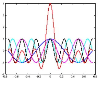
[image:21.612.248.408.130.269.2]2.2 Orthogonality
Figure 2.2.1: Orthogonal
Orthogonality is means the obviously the spectrums of the subcarriers are not separated but overlap. The reason why the information transmitted over the carriers can still be separated is the so called orthogonality relation giving the method its name. By using an IFFT for modulation we implicitly chose the spacing of the subcarriers in such a way that at the frequency where we evaluate the received signal (indicated as arrows) all other signals are zero. In order for this orthogonality to be preserved the following must be true:
1. The receiver and the transmitter must be perfectly synchronized. This means they both must assume exactly the same modulation frequency and the same time-scale for transmission (which usually is not the case).
2. The analog components, part of transmitter and receiver, must be of very high quality.
3. There should be no multipath channel.
23
2.3 Orthogonal Frequency Division Multiplexing (OFDM)
Orthogonal frequency-division multiplexing (OFDM) essentially identical to Coded OFDM (COFDM) and Discrete multi-tone modulation (DMT) is a frequency-division multiplexing (FDM) scheme utilized as a digital multi-carrier modulation method. A large number of closely-spaced orthogonal sub-carriers are used to carry data. The data is divided into several parallel data streams or channels, one for each sub-carrier. Each sub-carrier is modulated with a conventional modulation scheme (such as quadrature amplitude modulation or phase shift keying) at a low symbol rate, maintaining total data rates similar to conventional single-carrier modulation schemes in the same bandwidth.
OFDM has developed into a popular scheme for wideband digital communication, whether wireless or over copper wires, used in applications such as digital television and audio broadcasting, wireless networking and broadband internet access.
The primary advantage of OFDM over single-carrier schemes is its ability to cope with severe channel conditions for example, attenuation of high frequencies in a long copper wire, narrowband interference and frequency-selective fading due to multipath without complex equalization filters. Channel equalization is simplified because OFDM may be viewed as using many slowly-modulated narrowband signals rather than one rapidly-modulated wideband signal. The low symbol rate makes the use of a guard interval between symbols affordable, making it possible to handle time-spreading and eliminate intersymbol interference (ISI). This mechanism also facilitates the design of single-frequency networks, where several adjacent transmitters send the same signal simultaneously at the same frequency, as the signals from multiple distant transmitters may be combined constructively, rather than interfering as would typically occur in a traditional single-carrier system.
24 In OFDM, the sub-carrier frequencies are chosen so that the sub-carriers are orthogonal to each other, meaning that cross-talk between the sub-channels is eliminated and inter-carrier guard bands are not required. This greatly simplifies the design of both the transmitter and the receiver; unlike conventional FDM, a separate filter for each sub-channel is not required.
The orthogonality requires that the sub-carrier spacing is Δf = k/(TU) Hertz, where TU seconds is the useful symbol duration (the receiver side window size), and k is a positive integer, typically equal to 1. Therefore, with N sub-carriers, the total pass band bandwidth will be B ≈ N·Δf (Hz).
The orthogonality also allows high spectral efficiency, with a total symbol rate near the Nyquist rate. Almost the whole available frequency band can be utilized. OFDM generally has a nearly 'white' spectrum, giving it benign electromagnetic interference properties with respect to other co-channel users.
OFDM requires very accurate frequency synchronization between the receiver and the transmitter; with frequency deviation the sub-carriers will no longer be orthogonal, causing inter-carrier interference (ICI), cross-talk between the sub-carriers. Frequency offsets are typically caused by mismatched transmitter and receiver oscillators, or by Doppler shift due to movement. While Doppler shift alone may be compensated for by the receiver, the situation is worsened when combined with multipath, as reflections will appear at various frequency offsets, which is much harder to correct. This effect typically worsens as speed increases, and is an important factor limiting the use of OFDM in high-speed vehicles. Several techniques for ICI suppression are suggested, but they may increase the receiver complexity.
25 being concentrated. Similarly, time interleaving ensures that bits that are originally close together in the bit-stream are transmitted far apart in time, thus mitigating against severe fading as would happen when travelling at high speed.
However, time interleaving is of little benefit in slowly fading channels, such as for stationary reception, and frequency interleaving offers little to no benefit for narrowband channels that suffer from flat-fading (where the whole channel bandwidth is faded at the same time).
The reason why interleaving is used on OFDM is to attempt to spread the errors out in the bit-stream that is presented to the error correction decoder, because when such decoders are presented with a high concentration of errors the decoder is unable to correct all the bit errors, and a burst of uncorrected errors occurs.
A common type of error correction coding used with OFDM-based systems is convolutional coding, which is often concatenated with Reed-Solomon coding. Convolutional coding is used as the inner code and Reed-Solomon coding is used for the outer code usually with additional interleaving (on top of the time and frequency interleaving mentioned above) in between the two layers of coding. The reason why this combination of error correction coding is used is that the Viterbi decoder used for convolutional decoding produces short errors bursts when there is a high concentration of errors, and Reed-Solomon codes are inherently well-suited to correcting bursts of errors.
Newer systems, however, usually now adopt the near-optimal types of error correction coding that use the turbo decoding principle, where the decoder iterates towards the desired solution. Examples of such error correction coding types include turbo codes and LDPC codes. These codes only perform close to the Shannon limit for the Additive White Gaussian Noise (AWGN) channel, however, and some systems that have adopted these codes have concatenated them with either Reed-Solomon or BCH codes (on the DVB-S2 system) to improve performance further over the wireless channel.