Full Length Research Paper
Modeling and controller design of an industrial
hydraulic actuator system in the presence of friction
and internal leakage
M. F. Rahmat*, Zulfatman, A. R. Husain, K. Ishaque, Y. M. Sam, R. Ghazali and S. Md Rozali
Department of Control and Instrumentation Engineering, Faculty of Electrical Engineering, Universiti Teknologi Malaysia, UTM Johor Bahru, 81310 Skudai, Johor, Malaysia.
Accepted 08 June, 2011
This paper presents a robust controller scheme and its capabilities to control the position tracking performance of an electro-hydraulic actuator system. Sliding mode control with fixed and varying boundary layer is proposed in the scheme. It is aimed to compensate nonlinearities and uncertainties caused by the presence of friction and internal leakage. Its capabilities are verified through simulations in Matlab Simulink environment. The friction was represented by the LuGre model and the internal leakage was assumed to change. The results indicate that the scheme successfully improves the robustness and the tracking accuracy of the system. This improvement offers a significant contribution in the control of modern equipment positioning applications.
Key words: Hydraulic actuator, position control, sliding mode, internal leakage, friction.
INTRODUCTION
Electro-hydraulic actuator system has become one of the most important actuators in the recent decades. It offers many advantages such as good capability in positioning, fast and smooth response characteristics and high power density. Due to its capability in positioning, it has given a significant impact in modern equipments for position control applications. Its applications in position control can be found in production assembly lines, robotics, aircrafts equipments and submarine operations. However, excellent positioning in these applications requires an accurate electro-hydraulic actuator. Position tracking performance of an electro-hydraulic actuator can be assured when its robustness and tracking accuracy are guaranteed. Therefore, the development of a suitable controller which could reflect robustness and tracking accuracy is very significant.
There are number of problems appear in the position tracking performance of the system such as non-linearities, uncertainties and time-varying parameters. Nonlinearities and uncertainties in the system reduce the
*Correspondent author. E-mail: [email protected]. Tel: +607-55 35317. Fax: +607-+607-5566272.
robustness and tracking accuracy of the system. Reduction in the robustness and tracking accuracy might be caused by the existence of friction and internal leakage in the system. Friction is an undesirable characteristic which surely occurs in the mechanical systems such as electro-hydraulic actuator system. It is highly nonlinear and may result to tracking errors, limit cycles, and poor stick-slip motion (Cadunas et al., 1995; Olssen et al., 1998). Furthermore, it strongly leads to an inaccurate position control of the system. Therefore, it should be identified earlier in the system design. Internal leakage is also an unexpected characteristic that exists in the system. It commonly flows between a spool valve and its body. Leakage flow between the spool valve and body considerably dominates the orifice flow through the valve (Erylmaz and Wilson, 2000). Hence, it should be accounted in controller design.
using an adaptive scheme (Lischinsky et al., 1999). The rest are composed the Lyapunov-based controllers such as conventional Lypunov-based technique (Sekhavat et al., 2004), Sliding Mode Control (SMC) (Bonchis et al., 2001; Mihajlov et al., 2002; Wang et al., 2006), and Backstepping control (Zeng and Sepehri, 2008). Most of the above proposed work deals with the LuGre model in observing friction. However, there is little work which considers the internal leakage effect in the control of position tracking performance of the system. This includes the work of a typical modelling and compensation of internal leakage (Kalyoncu and Haydim, 2009), where a fuzzy logic control (FLC) was designed for the compensation. Due to the uncertainties elimination capability, SMC seems to be an attractive solution in electro-hydraulic actuator system.
SMC has emerged as a powerful tool in the control of position tracking performance of the system in view of the friction effect. It has been successfully implemented to compensate the effects of the load variations (Liu and Handroos, 1999) and uncertain original volume (Guan and Pan, 2008). It has number of features which ensure the stability, robustness and tracking accuracy. Therefore, SMC turns out to be a suitable choice in the control strategy of the system to compensate the existence of nonlinear behaviours (Hung et al., 1993). To the best of author’s knowledge, SMC abilities have not been tested for the system with the consideration of internal leakage problem. With the inclusion of internal leakage in the model of the system, capabilities of the controller to compensate the nonlinear behaviours become a more complete task.
In designing the SMC, the improvement of tracking accuracy currently has become one of the important issues. The tracking accuracy can be guaranteed using an appropriate sliding surface design (Hissein, 2005), the use of reaching law method (Hassan et al., 2001), and a thin boundary layer in the discontinuous term of the control law. A thin boundary layer can be either a fixed boundary layer (Mihajlov et al., 1999) or varying boundary layers (Chen et al., 2005). The varying boundary layer offers a smooth control action with very small chattering due to the change of tracking error bounds. The presence of friction and internal leakage in the electro-hydraulic actuator can cause the change of the tracking error bounds. Therefore a suitable varying boundary layer algorithm is required for the SMC design to result a more accurate position tracking and smoother control signal.
Pertaining to the preceding discussion, the SMC capabilities were utilized to compensate the presence of friction and internal leakage. The varying boundary layer is developed for the SMC and is compared with the fixed boundary. The mathematical model of the system is represented by integrating the friction and internal leakage model into the existing system model. The friction is modelled using the LuGre model on the position
tracking performance of the system. The influence of the internal leakage is classified in several levels due to the change in the tracking error bounds. A simulation study is carried out to show the tracking performance of the system by employing the proposed controller.
MODELLING OF ELECTRO-HYDRAULIC ACTUATOR SYSTEM
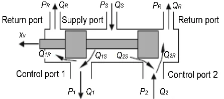
Servo valve and hydraulic cylinder are two important parts in the electro-hydraulic actuator system (Merritt, 1967). The hydraulic actuator is double-acting hydraulic cylinder with single-rod or single ended piston. A single load attached at the end of the piston without spring and damper (Zulfatman and Rahmat, 2009). From Figure 1, ps is the hydraulic supply pressure and pr is the return pressure. xv is the spool valve displacement, Q1 and Q2 are fluid flow from and to cylinder,and p2and p1are the fluid pressure in the upper and lower cylinder chambers of the actuator. When differences between p2 and p1 exist, the hydraulic cylinder extends or compresses.
The complete mathematical model of the system consists of the hydraulic actuator dynamics including the load and the servo-valve dynamics (Zulfatman and Rahmat, 2009; Avila et al., 2004). It describes characteristics and behaviours of the electro hydraulic system.
The mechanical subsystem dynamics of the piston is dependent on the damper and spring component which are placed in parallel to the piston as part of load environment. In this work, the damper and spring components do not exist in the system. Hence, the dynamic equations can be written as:
p
p v
x = (1)
f a
p
F
F
ma
=
−
(2)where, xp is the piston position, xpand vp are the piston velocity, ap is the piston acceleration, and m is total mass of piston and load. From equation (2), there are two forces that can be derived from the dynamics of the system: the hydraulic actuating force, Fa, and the hydraulic friction force, Ff. The hydraulic actuating force,
Fa, is a nonlinear function of the control input voltage, load environment, cylinder pressure, friction, and leakage. It can be represented as:
l P a A p
F = (3)
Hence,
f l P p A p F
ma = − (4)
xv
Figure 1. Electro-hydraulic actuator.
is the cylinder differential pressure. In this model pressure across the actuator piston, the derivative of the load pressure,pl, is given by the total load flow through the actuator. It divided by the fluid capacitance, and also taking leakage and compressibility into consideration.
p pressure of the cylinder are given by:
The corresponding relation can be simplified as:
) second order lag,
damping ratio of servo valve, respectively. From equation (1) to (10), if the state variables are selected can be obtained by neglecting the valve dynamic (9) and replaced byxv =kvu, which follows:
Substituting equation (4) and (8) into (13), we obtain
Hence, from equation (14), the piston motion is obtained as single input single output nonlinear systems:
Figure 2. Servo valve configuration.
Friction Model
Friction is a complex and a natural phenomenon. It occurs at the physical interface and the tangential reaction force between two surfaces in contact (Cadunas et al., 1995). It can lead to tracking errors, limit cycle oscillation and undesirable stick-slip motion (Olssen et al., 1998). Friction also appears in a hydraulic cylinder which produces strong dry friction effect, due to the tight sealing.
Friction is commonly modelled as a discontinuous static mapping between the velocity and the friction force. This friction force depends on the velocity’s sign which is restricted to Coulomb and viscous friction. However, a static model cannot explain several behaviours such as stick-slip motion, re-sliding displacement and friction lag. These properties are dynamic in nature; hence friction does not have an instantaneous response to a change of the velocity. In order to accommodate all properties in static and dynamic friction together, friction force is modelled as LuGre friction model (Olssen et al., 1998). The velocity-friction graph of this model is shown in Figure 3. This graph represents the friction characteristics for both static and dynamic frictions. The friction characteristics are generated during two cycle of oscillation. The oscillation results in a narrow hysteretic effects around the zero relative velocity in the graph (pre-sliding motion area) (Jerzy et al., 2008).
The LuGre friction model can be explain from the following equation:
p
f z z v
F =
σ
0 +σ
1 +σ
2 , (18)z v g
v v z
p p
p
) (
−
= (19)
The friction internal state describes the average deflections of the bristle, z, between each pair of the contact surface. Friction force parameters σ0, σ1, and σ2, respectively are interpreted as the stiffness of the bristle between two contact surfaces, bristles damping co-efficient, and viscous friction coefficient. Different friction
Figure 3. Friction-velocity description.
effects are described by a nonlinear function, g(vp) and can be parameterized to characterise the Stribeck effect:
), )
( ( 1 )
( ( / )2
0
s p v
v c s c
p F F F e
v
g = + − −
σ (20)
where, Fc, Fs, and vsare the Coulomb friction, viscous friction and Stribeck velocity, respectively. Thus, the complete friction model is represented by four static parameters and two dynamic parameters, stiffness coefficient and damping coefficient.
Internal leakage model
Internal leakage commonly flows between a servo valve and valve body. In an ideal servo valve, the leakage flows are zero, because it has a perfect geometry. In practice, the maximum leakage flow occurs at neutral spool position and is only a few percent of the rated flow rate. The leakage flow decreases rapidly with the valve stroke because of the large overlap between the spool lands and the valve body. In this paper, a nonlinear servo valve model is developed which accurately captures the leakage behaviour of the servo valve over the whole ranges of spool movement. The leakage behaviour is modelled as a turbulent flow. The flow area is inversely proportional to the overlap between the spool lands and the servo valve orifices (Erylmaz and Wilson, 2000).
R
The flow rate at the supply and the return side of the port 1 is given by the orifice equation:
), inversely proportional to spool displacement.
From equation (21) to (24), the following nonlinear relationships for control port 1 and port 2 were obtained.
matched control port.
R
As suggested by (Kalyoncu and Haydim, 2009), the total supply flow, QS, represents the internal leakage flow since the control ports are blocked for an internal leakage test. The internal leakage flow can be expressed as:
,
For any type of servo valve, available manufacturer data (Qmaxand Imax) can be used to determine the servo valve leakage parameters such as Kf, kf and x0 (Erylmaz and Wilson, 2000). The servo valve leakage flow can be tested by using several level equivalent orifice opening,
x0, from no leak to large leak (Kalyoncu and Haydim, 2009).
Integrated model
An integrated model of the system is performed by combining the existing model of electro-hydraulic actuator with LuGre friction model and internal leakage model. The friction model (18) to (20) is connected to the integrated system by supplying the derivative of the output into the model. While, internal leakage equations (26) to (29) are integrated in (6) and (7) to determine the total supply flow into chamber 1 of the cylinder.
SLIDING MODE CONTROL IN POSITIONING OF ELECTRO-HYDRAULIC ACTUATOR
The development of SMC for position tracking control of the hydraulic servo system consists of two steps. The first step is to select an equilibrium manifold or sliding surface, S(x), to prescribe the desired dynamic characteristic of the controlled system. The second one is to design a control law to drive the system to the sliding mode S(x) = 0 and to maintain it there forever (Hung et al., 1993). The control law of the sliding mode control is proposed as: and switching control, respectively.
Consider a nonlinear system described in control canonical form in (16). The following assumptions are known exactly and bounded as:
designed time-varying, and termdu is
Equivalent control
The objective of the control design is to achieve a various model uncertainties. In designing a desired trajectory, the state error of the system is defined as:
id equation (36) gives
e
Substituting x3from equation (16) gives:
d formulating the derivative of sliding surface S=0
)
Another control signal is the switching control signal, usw. It is designed to consider the uncertainties in the nonlinear dynamic, f, and to force all the trajectories states towards the sliding surface, S, and to maintain them on the sliding surface. Switching control guarantees that the state reaches the sliding mode in spite of uncertainties and disturbances.
) tracking accuracy in positioning, a smaller boundary layer is required. Hence an optimal balance between the position error and the level of control chattering can be accomplished by adjusting the thickness of the boundary layer φ>0.
By choosing the Lyapunov function as:
0 2 1 2 ≥
= S
V (43)
According to Lyapunov stability criterion which is described as:
0 <
V (44)
Then, to reach this condition it follows that:
) Substituting Sfrom equation (31) and (38) to (45) gives:
To meet the above condition, the discontinuous gain, K, in (42) is determined as
D q f E
K≥β( +η)+(β−1) ˆ+ˆ + (47)
where, du ≤D, f −fˆ ≤E (48)
and gain margin, β, is introduced as
1 / min
max ≥
= g g
β , (49) where, −1≥β
ˆg
g
Varying boundary layers
For better tracking accuracy and a smoother control input, a smaller width of boundary layer is required. However, the error trajectory changes due to nonlinearities and uncertainties in the system. Subsequently, the width of the boundary layer should also be changed to obtain an optimum tracking accuracy and smooth control input. Therefore, varying width of the boundary layers are proposed as:
)) ( 1 ( )
(e x e
x b
a + −
=φ φ
φ (50)
Hence, the switching control in (42) is rewritten as;
− + −
= −
)) ( 1 ( ) ( tanh ˆ 1
e x e
x S K
g u
b a
sw
φ
φ (51)
where, ϕa and ϕb are different level boundary layers, with 0<ϕb<ϕa. The logic for the boundary in the tracking error bounds defined as
and , e for 1 )
(e f
x = >ε x(e)=0 for e ≤εf (52)
εf is positive constant which is used to declare the switching threshold of the tracking error. The nitial state will be attached to the boundary layer of sliding surface, if the initial state is outside the boundary layer, |S|≥φa. The boundary layer changes from φa to φb, if the absolute value of the trajectory error, |e|, smaller than εf. It results a significant improvement for the tracking accuracy and the chattering.
Conditions and widths of φa and φb of the boundary layer in the tracking error bounds area need to be defined clearly. The boundary layer, φ, is obtained by try-and-error. Its value is accepted and stated when a visible chattering in the control input signal occurs. Then, the absolute value of φis set as φa. While, width of φb is set smaller than φa (in this proposed work it is around 1/6 of
φa), which is a small enough to ensure no chattering in
the control signal.
METHODOLOGY
The tracking performance of the controller design is evaluated through several tests. The parameters of the electro-hydraulic actuator system are taken from the manufacturer datasheet of an existing electro-hydraulic which in this study is composed of a single-rod and double acting hydraulic cylinder, which is driven by a direct servo valve Bosch Rexroth 4WREE6, 40 lpm flow rate at 70 bar. The dimensions of hydraulic cylinder are 63 × 30 × 300 (mm). Piston position is measured by using 300 mm draw wire sensor. The 100 bar pressure transducers are attached to measure the pressure into and out of the cylinder. Figure 4 depicts the complete test bed of electro-hydraulic system. The system parameters in the proposed work are shown in Table 1.
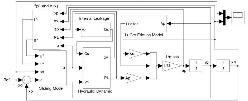
Figure 5 illustrates the overall Simulink block for the entire system. It includes several sub-system blocks such as the dynamic model of the system, the friction model, the internal leakage model, and the proposed controller design. The dynamic block consists of the system dynamics equation (1) to (16). Since the proposed work considers the behaviour of friction and internal leakage, the friction and the internal leakage blocks are attached in the complete system block. The friction and the internal leakage sub-blocks are created using equations (18) to (20) and (21) to (30), respectively. Output of the friction sub-block is dependent on the velocity of the piston, vp. While, output of the internal leakage sub-block, Qs, is influenced by position of the spool valve, xv. The value of Qsis added to the nominal flow, QL, to change the load pressure, pl. The proposed controller sub-block is employed to obtain a suitable control signal, u, to control the servo valve in voltage unit. The proposed controller sub-block is constructed using rules (31) to (49). Moreover, fixed and varying boundary layers are connected using a switch.
The control signals are derived to control motion of spool of the servo valve. Positions of the spool influence the nominal flow of oil into chamber 1 and also from chamber 2. The changes in nominal flow will change the volume and pressure inside each chamber of the cylinder, and finally affects the piston position of the actuator. Hence, the performance of the system will be dependent on the signal from the proposed controller.
In the proposed work, 50 mm square wave and step input signals are used to evaluate the performance of the system. The 50 mm amplitude is a visible value to represent the motion of the piston compare to the total stroke of the piston, 300 mm. 0.001 sec time sample and Runge-Kutta solver are used in simulation configuration. Several system characteristics can be obtained from responses of square wave such as overshoot, steady state error, rise time and settling time. These characteristics show the superiority of the proposed controller responses compared to other controller responses. In this work, the SMC is compared to conventional PID controller. Analysis of the responses have followed these criteria i.e. no overshoot, zero steady state error, fast rise time and settling time. During the simulations, parameters of the system, the friction, the internal leakage, and the proposed controller were set as in Table 1. The SMC and conventional PID controller parameters which are utilized in the system are shown in Table 2. The PID controller parameters in Table 2 are optimized using the established Ziegler-Nichols tuning method.
A number of simulation scenarios are utilized in the proposed work. These are described as:
Figure 4. Electro-hydraulic actuator system test bed.
Table 1. Parameters of the system.
Cylinder parameter
ps Supply pressure (Pa) 0.7×10⁷
pr Supply return (Pa) 0
Vt Total actuator volume (m3) 0.89×10⁻³ Ap Actuator ram area (m2) 2.97×10⁻³
L Total stroke of piston (m) 0.3
m Total mass of piston and load (kg) 18
βe Effective bulk modulus (Pa) 1×10
9
ρ Fluid mass density (kg/m2) 850
Servo valve parameter
Cd Discharge coefficient 0.6
Ct Total leakage coefficient 2×10-14 w Spool valve area gradient (m2) 0.02 kv Servo valve spool position gain (m/V) 1.27×10⁻⁵
ωv Servo valve natural frequency (Hz) 506.7
ζv Servo valve damping ratio 0.617
Imax Max. rate current to servo valve (A) 2 Qmax Max. permissible flow (l/min) 80
Leakage parameter
x0 Equivalent orifice opening 0 to 8×10⁻⁵
kf Leakage coefficient 0.3
Kf Flow gain 1.42x10⁻⁵
Friction parameter
Fs Static friction (N) 300
Fc Coulomb friction (N) 230
σ0 Bristles stiffness coefficient (N/m) 14×105
σ1 Bristles damping coefficient (N/ms-1) 340
σ2 Viscous friction (N/ms-1) 70
vp xp
xd xp
ap f(x) and b (x)
xp
vp
ap
PL
u f ^
g^
Sliding Mode g^
f ^
xd
e
u
LuGre Friction Model Vp Friction
Internal Leakage
xv Qs
1 s 1
s
Hydraulic Dynamic Qs
u
Vp
xv
PL Ref
ks
Ap
1/mass
1/M
Figure 5. Simulink block of the complete system.
Table 2. Parameters of the controllers.
SMC Parameter
λ 300
η 4200
E 0.5|fˆ|
gmin 0.8
gmax 1.2
ϕ 3.0
ϕα 3.0
ϕβ 0.5
εf 0.00035
PID controller parameter
Kp 1.85
Ki 0.01
Kd 0.0001
wave signals are used as reference input in this investigation.
Step 2: Sensitivity of SMC and conventional PID controller is compared with the consideration of friction and internal leakage. The fixed boundary layer is applied in the SMC. Effects of the internal leakage are achieved using 5 different levels of leakage by changing the value of equivalent orifice opening, x0, 0.0 m, 1x10⁻⁵ m, 2x10⁻⁵ m, 4x10⁻⁵ m, and 8x10⁻⁵ m, respectively. Step input signals are employed.
Step 3: In this step, performance of SMC is assessed against the fixed boundary and varying boundary layers. A short step input signals are applied for the SMC to investigate the chattering phenomena in the control action. The friction LuGre model is considered. A 2x10⁻⁵ m level of internal leakage is employed. The varying boundary layer parameters can be seen in Table 2.
RESULTS AND DISCUSSION
Figure 6 shows the output response of both the SMC and
conventional PID controllers. It can be seen that both controllers satisfactorily reaches the steady state without overshoot. A faster rise time of 0.20 sec and settling time 0.32 sec, respectively are recorded in the SMC responses compared to 3.35 sec and 8.80 sec in the conventional PID controller. Figure 7 shows that SMC control signal compensates the system to zero steady state error faster than the PID control signal. However, the SMC contributes a small chattering in its control signals. This chattering appears in the control signal due to the discontinuous term in the control law of the SMC.
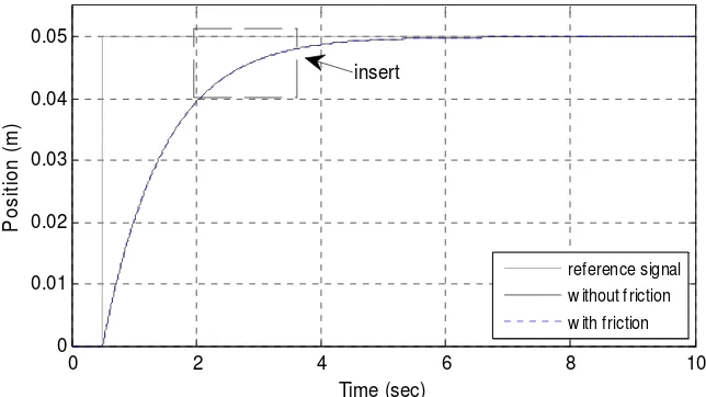
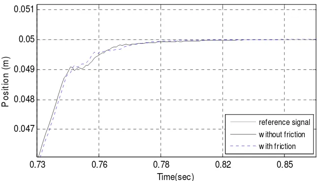
Friction usually affects the tracking performance of the hydraulic actuator. This observation can be seen in Figures 8a and 8b, where PID controller is unable to track the desired input. Figures 9a and 9b show the tracking performance of SMC. Although, friction has degraded the tracking but still SMC can track the desired input satisfactorily. Only a slight reduction in rise and settling time is seen which clearly highlights the performance of SMC.
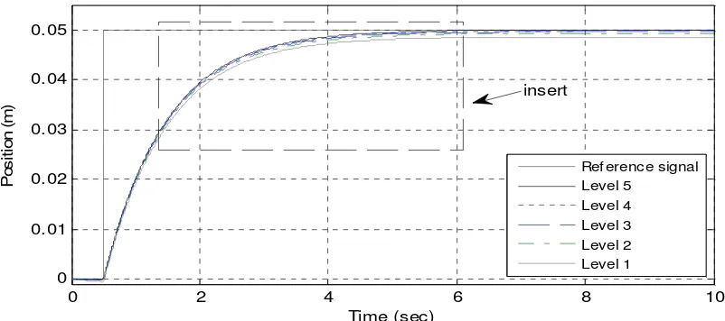
Internal leakage is one of the dominant factors, which affects the performance of hydraulic actuator. Most of the previous works neglected this effect, but the practical results strongly deny this fact. Maximum leakage flow occurs at neutral spool position, and decreases when the spool displacement turned into the maximum stroke. When the leakage level changed to the higher level or in another word the stroke is maximum value, the leakage flow on the electro-hydraulic actuator position is reduced and the system is closer to the desired output. From Figures 10a to 11b, it can be seen that, in the presence of internal leakage, the system with SMC is significantly betterthanconventionalPIDcontroller.SMC satisfactorily maintains the tracking performance. These results reveal that the SMC is insensitive to internal leakage.
0 5 10 15 20 25 30 35 40 -0.06
-0.04 -0.02 0 0.02 0.04 0.06
Time (sec)
P
o
s
it
io
n
(
m
)
Ref erence PID Controller SMC
Figure 6. Response of the system using square wave input signal.
0 5 10 15 20 25 30 35 40
-10 -5 0 5 10
Time (sec)
S
ig
n
a
l
U
(
V
o
lt
)
SMC PID Controller
Figure 7. Control signal of the system using square wave input signal.
0 2 4 6 8 10
0 0.01 0.02 0.03 0.04 0.05
Time (sec)
P
o
s
it
io
n
(
m
)
reference signal w ithout friction w ith friction insert
2.27 2.64 3.01 0.04
0.042 0.044 0.046 0.048 0.05
Time (sec)
P
o
s
it
io
n
(
m
)
reference signal w ithout friction w ith friction
Figure 8b. Insert of Figure 8a.
0 2 4 6 8 10
0 0.01 0.02 0.03 0.04 0.05
Time(sec)
P
o
s
it
io
n
(
m
)
reference signal w ithout friction w ith friction insert
Figure 9a. Response of the system with friction controlled by SMC.
0.73 0.76 0.78 0.82 0.85
0.047 0.048 0.049 0.05 0.051
Time(sec)
P
o
s
it
io
n
(
m
)
reference signal w ithout friction w ith friction
0 2 4 6 8 10 0
0.01 0.02 0.03 0.04 0.05
Time (sec)
P
o
s
it
io
n
(
m
)
Ref erence signal Level 5
Level 4 Level 3 Level 2 Level 1 insert
Figure 10a. Response of the system with several levels of leakage controlled by PID Controller.
2 4 6
0.03 0.035 0.04 0.045 0.05
Time (sec)
P
o
s
it
io
n
(
m
)
Reference signal Level 5
Level 4 Level 3 Level 2 Level 1
Figure 10b. Insert of Figure 10a.
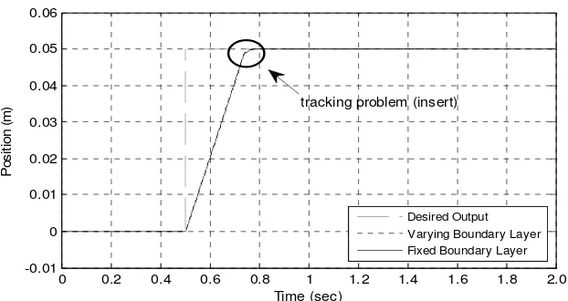
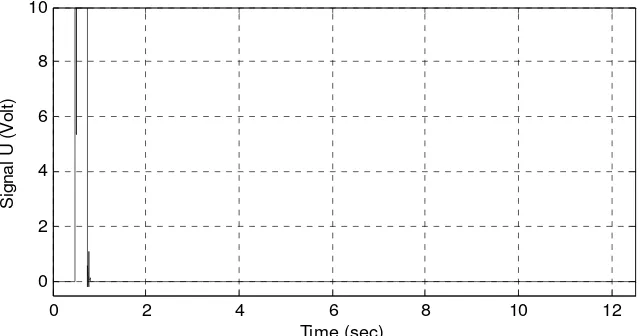
Figures 12a and 12b show the output response of the system with SMC, which produce better performance in the case of varying boundary layer. This can be observed by comparing Figures 13 and 14, where SMC with varying boundary layer has considerably less chattering. Based on the preceding discussions, SMC has been shown to have good capabilities in compensating and handling the friction and internal leakage inside the system. The nonlinear SMC controller keeps the system states on its sliding surface, even when there are varying uncertainties appearing. These properties improve the robustness and tracking accuracy of the electro-hydraulic actuator in positioning. Hence, the implementation of the proposed SMC controller on the electro-hydraulic actuator system can offer a significant improvement in
modern equipment positioning applications.
CONCLUSIONS
0 2 4 6 8 10 0
0.01 0.02 0.03 0.04 0.05
Time (sec)
P
o
s
it
io
n
(
m
)
Reference signal Level 5 Level 4 Level 3 Level 2 Level 1 insert
Figure 11a. Response of the system with several levels of leakage controlled by SMC.
0.73 0.78 0.83 0.88 0.93
0.048 0.0485 0.049 0.0495 0.05
Time (sec)
P
o
s
it
io
n
(
m
)
Ref erence signal Level 5 Level 4 Level 3 Level 2 Level 1
Figure 11b. Insert of Figure 11a.
0 0.2 0.4 0.6 0.8 1 1.2 1.4 1.6 1.8 2.0 -0.01
0 0.01 0.02 0.03 0.04 0.05 0.06
Time (sec)
P
o
s
it
io
n
(
m
)
Desired Output Varying Boundary Layer Fixed Boundary Layer tracking problem (insert)
0.7 0.75 0.8 0.85 0.045
0.046 0.047 0.048 0.049 0.05
Time (sec)
P
o
s
it
io
n
(
m
)
Desired Output Varying Boundary Layer
Fixed Boundary Layer
Figure 12b. Insert of Figure 12a.
0 2 4 6 8 10 12
0 2 4 6 8 10
Time (sec)
S
ig
n
a
l
U
(
V
o
lt
)
Figure 13. Control signal of the system with fixed boundary layer.
0 2 4 6 8 10 12
0 2 4 6 8 10
Time (sec)
S
ig
n
a
l
U
(
V
o
lt
)
boundary layer in the controller.
ACKNOWLEDGMENTS
This research is supported by Ministry of Higher Education (MOHE) Malaysia and Universiti Teknologi Malaysia (UTM) through Fundamental Research Grant Scheme (FRGS) vot number 78591. Authors are grateful to the Ministry and UTM for supporting the present work.
Nomenclatures
Ap Cross section area (m
2
)
ap Piston acceleration (m/s2)
p
a Piston jerk (m/s3)
Cd Discharge coefficient
Ct Total leakage coefficient
du External disturbance
D Maximum disturbance
e Error trajectory
e Derivative of error
E Error bounded
Fa Hydraulic actuating force (N)
Fc Coulomb friction (N)
Ff Hydraulic friction force (N)
f
F Derivative of friction force Fs Static friction (N)
f Nonlinear dynamics
f
ˆ Estimation of nonlinear dynamics
g Control gain
gˆ Estimation of control gain
gmin Lower bound of control gain
gmax Upper bound of control gain
Imax Max. current for servo valve
K Discontinuous gain
Kf Flow gain
K1R,K2R Flow gain at return port 1 and 2
K1S,K2S Flow gain at supply port 1 and 2
kf Leakage coefficient
k1R,k2R Leakage coefficient at return port 1 and 2
k1S,k2S Leakage coefficient at supply port 1 and 2
kv Servo valve gain (m/V)
L Total stroke of piston (m)
m Total mass of piston and load (kg)
pl Load pressure (Pa)
l
p Derivative of load pressure (Pa/s)
pr Return pressure (Pa)
ps Supply pressure (Pa)
p1, p2 Pressure in chamber 1 and 2 (Pa)
QL Nominal flow (m3/s)
Qs Internal leakage flow (m3/s)
Q1, Q2 Fluid flow in chamber 1 and in chamber 2 (m3/s)
Q1R,Q2R Return flow at return port 1 and 2 (m3/s)
Q1S,Q2S Supply flow at supply port 1 and 2 (m3/s)
Qmax Maximum permissible flow (l/min)
S Sliding surface
S Derivative of sliding surface u Input signal to the servo valve (V)
ueq Equivalent control signal (V)
usw Switching control signal (V)
V Lyapunov function
V Derivative of Lyapunov function
vp Piston velocity (m/s)
vs Stribeck velocity (m/s)
Vt Total actuator volume (m
3
)
w Spool valve area gradient (m2)
xd Desired position (m)
xp Piston position (m)
xv Spool valve displacement (m)
v
x
Spool valve velocity (m/s)v
x Spool valve acceleration (m/s2)
x0 Equivalent orifice opening (m)
p
x
Piston velocity (m/s)z Average of bristle deflection
z Derivative of average of bristle deflection
Greek Symbols
ωv Servo valve natural frequency (Hz) βe Effective bulk modulus (Pa) ζv Servo valve damping ratio τv Time constant (s)
φ Thickness of boundary layer
φ
a 1st level of boundary layerφb 2
nd
level of boundary layer
σ0 Bristles stiffness coefficient (N/m) σ1 Bristles damping coefficient (N/ms-1) σ2 Viscous friction (N/ms
-1
) ρ Fluid mass density (kg/m3)
f
ε Switching threshold of the tracking error
REFERENCES
Avila MA, Loukianov AG, Sanchez EN (2004). Electro-hydraulic actuator trajectory tracking. Proceedings of the 2004 American Control Conf.Boston, Massachusetts: 2603-2608.
Bonchis A, Corke PI, Rye DC, Ha QP (2001). Variable structure methods in hydraulic servos systems control. Automatica, 37: 589-595.
Cadunas de Wit C, Olsson H, Astrom KJ, Lischinsky P (1995). A new model for control of systems with friction. IEEE Trans. Automatic Control,40(3): 419-425.
Chen HM, Renn JC, Su JP (2005). Sliding mode control with varying boundary layers for an electro-hydraulic position servo system. Int. J. Adv. Manu. Tech., 26: 117-123.
Erylmaz B, Wilson BH (2000). Combining leakage and orifice flows in a hydraulic servovalve model. J. Dynamic Systems Measurement Control, 122: 576-579.
Guan C, Pan S (2008). Adaptive sliding mode control of electro-hydraulic with nonlinear unknown parameters.Control Eng. Practice, 16: 1275-1284.
Hassan IMM, Mohamed AM, Saleh AI (2001). Variable structure control of a magnetic suspension system. Proc. of the 2001 IEEE Conf. on Control Appl., Mexico City, Mexico, Sept. 5-7: 333-338.
System. Proc. of the 2005 IEEE Conf. on Control App. Toronto, Canada: pp. 422-427.
Hung JY, Gao W, Hung JC (1993). Variable structure control: a survey. IEEE Trans. Ind. Electronics, 40(1): 2-21.
Jerzy W, Andrzej S, Marian W, Thomasz K (2008). Hysteretic effects of dry friction: modelling and experimental studies. Phil. Trans. R. Soc. A., 366: 747-765.
Kalyoncu M, Haydim M (2009). Mathematical modelling and fuzzy logic based position control of an electrohydraulic servosystem with internal leakage. Mechatronics,19: 847-858.
Lischinsky P, Canudas de W, Morel G (1999). Friction compensation for an industrial hydraulic robot. IEEE Control Systems. February: 25-32. Liu Y, Handroos H (1999). Technical note sliding mode control for a
class of hydraulic position servo. Mechatronics,9: 111-123. Merritt HE (1967). Hydraulic Control Systems. John Wiley and Sons. Mihajlov M, Nikolic V, Antic D (2002). Position control of electro
hydraulic servo system using sliding mode control enhanced by Fuzzy PI controller. Facta Univ. Series: Mech. Eng., 1(9): 1217–1230. Olsson H, Astrom KJ, Cadunas de Wit C, Gafvert M, Lischinsky P (1998). Friction models and friction compensation. Euro. J. Control, 4(3): 176-195.
Sekhavat P, Wu Q, Sepehri N (2004). Lyapunov-based friction compensation for accurate positioning of a hydraulic actuator. Proc. of the 2004 American Control Conf., Boston, Massachusetts, USA, June 30 – July 2: 418-423.
Tafazoli S, De Silva CW, Lawrence PD (1998). Tracking control of an electrohydraulic manipulator in the presence of friction. IEEE Trans. Control Systems Tech., 6(3): 401-411.
Wang S, Habibi S, Burton R, Sampson E (2006). Sliding mode control for a model of an electrohydraulic system with discontinuous nonlinear friction. Proceedings of the 2006 American Control Conf., Minneapolis, Minnesota, USA, June 14-16: 418-423.
Zeng H, Sepehri N (2008). Tracking control of hydraulic actuators using a LuGre friction model compensation. J. Dynamic Systems Measurement Control, ASME., 130: 1-7.