Radial Line Slot Array Antenna Development in
Malaysia
I.M. Ibrahim
1,2, T. Purnamirza
2,3, T.A.Rahman
2, M.I.Sabran
21
Faculty of Electronics and Computer Engineering, Universiti Teknikal Malaysia Melaka, Malaysia 2
Wireless Communication Centre, Universiti Teknologi Malaysia, Skudai, Johor, malaysia 3
Department of Electrical Engineering, Universitas Islam Negeri Sultan Syarif Kasim, Indonesia
Abstract—The Radial Line Slot Array (RLSA)
antennas become more popular due to its good characteristics such as low profile, low cost, aesthetically pleasing, ease of installation and simple structure. Many researchers have contributed to the development of RLSA antennas. This antenna started with the name of annular slot antenna designed by Kelly and Goebel in 1960’s. In 1980’s, the researchers from Japan have innovated this idea and proposed a new concept of radial slot planar antenna names Radial Line Slot Antenna. From here, many researches have been carried out involving researchers around the world. Researchers from Malaysia also involves in the development of RLSA antenna. The RLSA antenna research in Malaysia focuses on application that suitable to RLSA characteristic. Those applications are Direct Broadcast Satellite Reception, Point to point Microwave Link for Fixed Broadband Wireless Access and RFID. This paper will be focus on RLSA antenna development started with the history, research outcomes and the research focus in Malaysia.
Index Terms—RLSA antenna, Direct Broadcast Satellite Reception, Point to Point Microwave Link, Beam Squinted RLSA, Beam Steering RLSA
I. INTRODUCTION
RLSA antenna research in Malaysia started early 2000 with collaboration with Queensland University, Australia. The focus research at that time was development of RLSA for Direct Broadcast Satellite Reception at KU-band [1]. The first RLSA research team in Malaysia was setup at Wireless Communication Research Laboratory (currently known as Wireless Communication Centre), Faculty of Electrical Engineering, Universiti Teknologi Malaysia. This research team was lead by Prof Dr Tharek Abdul Rahman and successfully investigated 18 prototypes to be implemented in DBS system in Malaysia. The final success prototype was the Beamsquint with linear polarization RLSA. It was successfully develop and measured. The same technique than been investigated for application 5.8GHz for point to point microwave link. A few prototypes successfully develop and measured. The test bed arrangement also has been developed to
verify the performance of the RLSA for that application [2-4]. At this stage, the usage of low value of dielectric as a substrate was widely apply to RLSA prototypes from researchers around the world [4-6]. The dielectric substrate than replaced by the FR4 board due to durability and easy to manufacture the antenna. The FR4 board contain higher dielectric value and able to reduce antenna size [7-8]. The measurement result shows a directive characteristic of radiation pattern. This research has lead to development of RLSA with beam shaping capability for RFID application. The configurable slot type feeder to the RLSA slot has introduced beamshaping characteristic to a new RLSA concept [9-10]. This research has lead to the investigation of multi dielectric substrate to reduce the reflection coefficient of RLSA [11]. The different stacked dielectric substrate has introduced different phase of signal inside the cavity. Thus, it has reduced the amplitude of the multi signal and reflection coefficient of the RLSA. This research has lead to wideband RLSA using open ended air gap. This wideband RLSA has been developed for point to point microwave link application with limited antenna diameter which is 200mm [12]. This antenna has successfully developed and measured and produced a good directive characteristic with wideband capability.
II. RLSA DEVELOPMENT IN MALAYSIA
A. RLSA For Direct Broadcast Satellite Reception Application at KU-Band
Figure 1: The radiation pattern of RLSA for DBS Application
The final prototype was integrated with ASTRO DBS Reception System to test the reception capability. The 64.5 dBuV of signal strength as recorded and the system successfully projected a video image on the television screen with audio.
B. RLSA For Point to Point Microwave link Application For Fixed Broadband Wireless Access at 5.8GHz Band
The research of RLSA continues with development of RLSA antenna at 5.8GHz frequency band for Fixed Broadband Wireless Access. The researcher has tried to scale down the antenna diameter and get the optimum size of antenna [2-4]. The first prototype with 600mm diameter has shown a very good directivity characteristic with low side lobe and back lobe level. The radiation pattern shown in Figure 2. A 26 dBi gain antenna with 63.1% radiation efficiency has successfully constructed and tested. The optimization of the antenna size was done to get the effective antenna size with a good directivity characteristic. Four prototypes with difference size has been constructed and measured [4].
Figure 2: The radiation pattern of 600mm RLSA for application at 5.8GHz Table 2: The summary of the prototypes result
The prototype antenna also tested using Redline AN50 system. This system operated at 5.8GHz band and commercially used for outdoor WLAN. The test result showed at Figure 3. The prototype antenna was successfully function to the Redline AN50 system and performed good reception. The test has been conducted between Wireless Communication Centre Building to a new hostel building in Universiti Teknologi Malaysia. The test bed shown in Figure 4. This research considered success and met the research objectives.
Figure 3: Internet access data from Redline AN50 using prototype antenna at 5.8GHz band
Figure 4: A trial of Point to Point Microwave Link using RLSA for FBWA application at 5.8GHz in Universiti Teknologi Malaysia
C. Implementation of FR4 board as a cavity material for RLSA
0.0 0.2 0.4 0.6 0.8 1.0 1.2
Figure 5: RLSA antenna structure using stacked FR4 board
The antenna size has been reduced to below 200mm diameter but demonstrated directivity characteristic as shown in Figure 6 with 14 dB of return loss at 5.8GHz. Far-field amplitude of STUDENT PROF PAK 5.8.nsi
Figure 6: Radiation pattern for FR4 based RLSA
D. Reconfigurable RLSA Antenna
The usage of FR4 board has lead the research into a design of reconfigurable beam shaping of RLSA antenna. This design utilised reconfigure slot as the feeders to feed the signal into RLSA slot at the radiating surface and perform the reconfigurability of the antenna [9-10]. Each feed slot will be configure the ON and OFF mode to create the reconfigure condition of the antenna. The reconfigure circuit was develop to allow the system administrator perform reconfigurability of the antenna. The design shown in Figure 7.
Figure 7:Photograph of the R-RLSA antenna (a) Feed line with PIN diodes switches (b) Aperture slots (c) RLSA radiating surface (d) Side view (e) Layout view
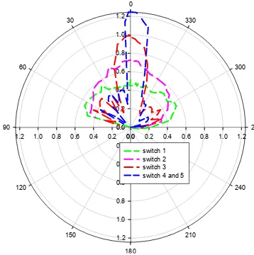
Figure 8 shows the polar graphs of radiation pattern measurements which are normalized to their peak values. The R-RLSA antenna has a gain of 4.3 dB and a beamwidth of 137°, when the first switch of EBRS is turned ON. By turning ON the first and second switch of the EBRS, the main beam would have a gain of 6.8 dB as well as beamwidth of 88°.
The increment of gain up to 8.6 dB and a narrower beamwidth of 39° by turning ON the first, second and third switches of the EBRS. The main radiated beam has produced a gain of 13.8 dB and a beamwidth of 24° when the first, second third and fourth switches of the EBRS are ON. The complete radiation pattern of beam shape is shown in Figure 8.
Figure 8: The overall measurement of beam shape radiation patterns by turning ON the EBRS
Frequency (GHz)
2.30 2.35 2.40 2.45 2.50
re
tu
rn
l
o
ss (d
B
)
-18 -16 -14 -12 -10 -8 -6 -4 -2
i switch of EBRS i and ii switches of EBRS i,ii and iii switches of EBRS i,ii,iii,iv and v switches of EBRS All the BRS
i,ii,iii,and iv switches of EBRS and vi and vii of BRS
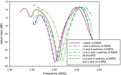
switches, 3 activated switches and 4 activated switches of EBRS are 15.62 dB, 16.04 dB, 16.35 dB and 17.7 dB respectively. Meanwhile the BRS’s return losses are stated at 15.8 dB and 16.32 dB for both divisive and single-sided broadside radiation pattern. It is found that all the cases of R-RLSA are above 10 dB.
Figure 9: Return loss of measured R-RLSA
This research successfully demonstrate the capability of RLSA to become a candidate of smart antenna in future. Since RLSA containt many slots that arranged in different position to create add in phase wave excitation, the beamwidth of the antenna can be reconfigure by feed the wave in to a certain angle to certain group of slot on overall slots of RLSA. This research also cerate a revolution in application using RLSA.
E. Techniques to develop small RLSA antennas
The main problem to develop small aperture RLSA (SA-RLSA) is a low efficiency. Purnamirza in [11] introduced a FR4 technique to reduce the reflection coefficient SA-RLSA antennas. In this technique, a FR4 board is added on the top of the RLSA antenna. Differently from the previous researches, the dielectric part of the FR4 board is not utilized as the antenna cavity, but as the other dielectric material that has different permittivity. The different permittivity between FR4 material and the cavity material polypropylene result a difference phase between the signals propagating within the FR4 material and the signals propagating in the cavity material. Hence, these signals will not reinforce one to each other if they come together, then lowering the reflection coefficient. Figure 10 shows the prototype of the SA-RLSA designed using FR4 technique [11].
Figure 10 (a) The radiating element (b) Figure a is seen from the side (c).The cavity
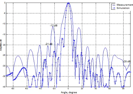
The study to the simulation and measurement results shows that the FR4 technique can reduce the reflection coefficient up to -25 dB as shown by Figure 11.
Figure 11: The simulation and the measurement results
F. Wideband Open Ended RLSA Antenna
In this research, the FR4 board with air gap distance to the ground plane has been introduced [12]. The thickness of overall cavity is 9.6mm where the thickness of open air gap is 8mm. A 50Ω single coaxial probe coated with Teflon is used to feed the signal into the cavity. The aluminum plate is used as a platform to hold the antenna and also become a ground plane. The FR4 with 1.6mm thickness with 5.4 permittivity value is used as a first layer substrate to the radiating surface. Figure 12 show the side view of fabricated open ended Air Gap RLSA structure
Figure 12: Fabricated open ended Air Gap RLSA Structure from side view
Figure 13 shows the reflection coefficient of the RLSA. The air gap has been optimized from 7mm to 10mm of thickness [12]. An air gap function is tuning the resonant frequency at desired target frequency. From measurement result, the air gap of 8mm response efficiently at 5.8GHz centre frequency with 32% of bandwidth. The reflection coefficient started at 4.23GHz to 6.21GHz.
Figure 13: Measured reflection coefficient of Air Gap RLSA with FR4 board (simulation) with FR4 board (measurement) No FR4 board (measurement) No FR4 board (simulation)
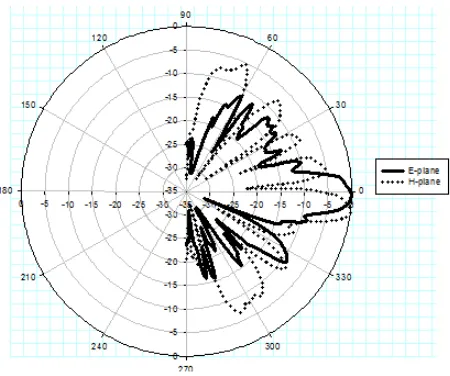
Figure 14 shows the radiated radiation pattern of the Air Gap RLSA at E and H plane. The antenna gain recorded at 14.91dBi with 8.7 dB side lobe level at E plane and 5dB at H plane. The main lobe squinted at 8 degree from 0 degree at E plane. The beamwidth of the main lobe is 13.5 degree at E plane and 5 degree at H plane. In overall, the radiation pattern shown directive characteristic and have a suitable to be implement to point to point application.
Figure 14: Measured radiation pattern of Air Gap RLSA
Normally, RLSA antenna produced a narrow bandwidth characteristic. This research successfully demonstrate the wide bandwidth of RLSA by implemented open ended air gap as a cavity for RLSA. A minimum number of slots has been introduced due to size limitation but generated a directivity characteristic of antenna. The new antenna structure also easy to fabricate and posible low cost on mass production. This research also cerate a revolution in application using RLSA.
III. CONCLUSION
In a decade, RLSA antenna research has been successfully carried out in Malaysia. The research are more focus on latest application possible for RLSA. The applications explore in RLSA research in Malaysia beside Direct Broadcast Satellite applications are Point to Point Microwave Link and RFID applications. The intention to make RLSA become a candidate of smart antenna has been carried out through reconfigurable feeder system of RLSA. The research also focus on simplifying the design and fabrication process and also reducing the antenna size but maintaining the directivity characteristic.
IV. ACKNWOLEDGEMENT
The authors would like to acknowledge and express sincere appreciation to Universiti Teknologi Malaysia and Ministry of Higher Education (MOHE) for financing the research project under the Research University Grant (RUG), title : Rain propagation studies and mitigation technique at 26GHz using 5.8GHz for point to point application, vote no: Q.J130000.7123.01H05. Appreciation also goes to Universiti
Teknikal Malaysia Melaka and MOHE for funding the author’s scholarship.
The appreciation also goes to all researchers and technical personnel involve in RLSA research in Malaysia from the first step until now.
REFFERENCES
[1] T. S. Lim, A. R. Tharek, W. A. Wan Khairuddin, and A. Hasnain, "Prototypes development for reflection canceling slot design of radial line slot array (RLSA) antenna for direct broadcast satellite reception," in Applied Electromagnetics, 2003. APACE 2003. Asia-Pacific Conference on, 2003, pp. 34-37.
[2] M. I. Imran and A. R. Tharek, "Radial line slot antenna development for outdoor point to point application at 5.8GHz band," in RF and Microwave Conference, 2004. RFM 2004. Proceedings, 2004, pp. 103-105.
[3] M. I. Imran, A. Riduan, A. R. Tharek, and A. Hasnain, "Beam squinted Radial Line Slot Array antenna (RLSA) design for point-to-point WLAN application," in Applied Electromagnetics, 2007. APACE 2007. Asia-Pacific Conference on, 2007, pp. 1-4.
[4] M. I. Imran, A. R. Tharek, and A. Hasnain, "An optimization of Beam Squinted Radial Line Slot Array Antenna design at 5.8 GHz," in RF and Microwave Conference, 2008. RFM 2008. IEEE International, 2008, pp. 139-142.
[5] M. Unno, J. Hirokawa, and M. Ando, "A Double-Layer Dipole-Array Polarizer with a Low-Sidelobe Radial Line Slot Antenna," in Microwave Conference, 2007. APMC 2007. Asia-Pacific, 2007, pp. 1-4.
[6] J. I. Herranz-Herruzo, A. Valero-Nogueira, E. Alfonso-Alos, and D. Sanchez-Escuderos, "New topologies of radial-line slot-dipole array antennas," in Antennas and Propagation, 2006. EuCAP 2006. First European Conference on, 2006, pp. 1-5.
[7] M. R. ul Islam and T. A. Rahman, "Novel and simple design of multi layer radial line slot array (RLSA) antenna using FR-4 substrate," in
Electromagnetic Compatibility and 19th International Zurich Symposium on Electromagnetic Compatibility, 2008. APEMC 2008. Asia-Pacific Symposium on, 2008, pp. 843-846.
[8] M. R. Ul Islam, L. Faisal, and T. Abd Rahman, "Simple integrated system for wireless backhaul networks," in Computer and Communication Engineering, 2008. ICCCE 2008. International Conference on, 2008, pp. 341-345.
[9] M. F. Jamlos, O. A. Aziz, T. A. Rahman, M. R. Kamarudin, P. Saad, M. T. Ali, and M. N. Md Tan, "A Reconfigurable Radial Line Slot Array (RLSA) Antenna for Beam Shape and Broadside Application," Journal of Electromagnetic Waves and Applications, vol. 24, pp. 1171-1182, 2010/01/01 2010.
[10] M. F. Jamlos, O. A. Aziz, T. A. Rahman, M. R. Kamarudin, P. Saad, M. T. Ali, and M. N. Md Tan, "A Beam Steering Radial Line Slot Array (RLSA) Antenna with Reconfigurable Operating Frequency," Journal of Electromagnetic Waves and Applications, vol. 24, pp. 1079-1088, 2010/01/01 2010.
[11] T. Purnamirza and T. A. Rahman; "A Novel Technique In Simplifying The Fabrication Process And Improving The Reflection Coefficient Of The Linear Polarized Radial Line Slot Array (LP-RLSA) Antennas," Journal of Electromagnetic Waves and Application, Vol. 26, 535–548, 2012