AN AERODYNAMIC STUDY ON MPV SPOILER
RAGUVARAN A/L JAYAHKUDY
RAGUVARAN A/L JAYAHKUDY
NAME : RAGUVARAN A/L JAYAHKUDY
MATRIC.NO : B041010046
COURSE : 4 BMCA
SUPERVISOR : NAZRI HUZAIMI BIN ZAKARIA
EVALUVATOR 1 : Mohd Haizal Bin Mohd Husin
AN AERODYNAMIC STUDY ON MPV SPOILER
RAGUVARAN A/L JAYAHKUDY
This report is submitted in partial fulfillment of the requirements for the award of the degree in Bachelor of Mechanical Engineering (Automotive)
Faculty of Mechanical Engineering University Teknikal Malaysia Melaka
SUPERVISOR DECLARATION
“I hereby declare that I have read this thesis and in my opinion this report is sufficient in terms of scope and quality for the award of the degree of
Bachelor of Mechanical Engineering (Automotive)”
Signature: ………
STUDENT’S DECLARATION
“I hereby declare that the work in this report is my own except for summaries and quotations which have been duly acknowledged.”
ACKNOWLEDGEMENT
ABSTRACT
ABSTRAK
4.1.2 Multi Purpose Vehicle with rear spoiler (MPVs) 39 original full specification
(90degrees + 20cm length, 8cm height)
4.1.3 Multi Purpose Vehicle with rear structured spoiler 41 (MPVss) (100degrees + 50cm length, 8cm height)
4.2 Graphical Analysis 43
4.3 Comparison of MPV, MPVs & MPVss Model 44
CHAPTER 5 CONCLUSION & RECOMMENDATIONS 51
REFERENCES 53
APPENDICES 56
LIST OF TABLES
NUM. TITLE PAGE
NUM. TITLE PAGE
3.3 CATiA model (Proton Exora) without rear spoiler, named MPV 21 3.4 CATiA model (Proton Exora) with rear spoiler 22
3.8 “Meshing Process” of the MPV model 26
3.9 “General Setup” of the MPV model 27
3.10 “Models & Materials “setup of the MPV model 28 3.11 Boundary Conditions “Velocity-Inlet & Pressure Outlet” 29 for the MPV model
3.12 Reference Values of the MPV model 30
3.13 Solution Methods, Controls & Initialization of the MPV model 31
3.14 Calculation Activities of the MPV model 32
4.1 Contours of Pressure on MPV model 37
4.7 Contours of Velocity Magnitude on MPVs model 40
(Maximum Velocity = 60.8m/s)
4.8 Contours of Turbulence Kinetic Energy on MPVs model 40 (Maximum Kinetic Energy = 200.65m2/s2)
4.14 Graph of model’s Lift Coefficient 47
4.15 Graph of model’s Drag Force 48
4.16 Graph of model’s Lift Force 48
LIST OF ABBREVIATIONS
MPV = Multi Purpose Vehicle without spoiler
MPVs = Multi Purpose Vehicle with spoiler / original full specification (90degrees + 20cm length, 8cm height)
MPVss = Multi Purpose Vehicle with structured spoiler (100degrees + 50cm length, 8cm height) CFD = Computational Fluid Dynamic
3D = Three Dimensional SUV = Sport Utility Vehicle F1 = Formula one
CAD = Computer Aided Design ANSYS = Simulation Software
Fluent = Simulation System/Process
CHAPTER 1
INTRODUCTION
1.1 PROJECT INTRODUCTION
and handling at highway speeds and also minimization of harmful interactions [4] with other vehicles on the roadways.
Rear spoiler is a component to increase down force for vehicle especially passenger car. It is an aerodynamic device that design to ‘spoil’ unfavorable air movement across a car body. Main fixing location is at rear portion, depends on shape of the rear portion either the MPV’s is square back, notchback or fastback because not all rear spoiler can be fix at any type of rear portion of a MPV. Rear spoiler contributed some major aerodynamics factor which is lift and drag. The reduction of drag force can save fuel; moreover spoiler can also be used to control stability at cornering [5]. Besides that, it even functions to reduce drag and reduce rear-axle lift.
1.2 PROBLEM STATEMENT
study on MPV spoiler. Before preceding this project study, several scopes and objectives of this study have to be defined clearly and precisely. This is very essential in order to carry out this study successfully. Therefore the objectives of this study are mentioned below:-
To study an aerodynamics on MPV vehicle with spoiler using Computational Fluid Dynamics (CFD) software.
To analyze the aerodynamics of the MPV spoiler using CFD software.
To design a simple MPV spoiler and to run the CFD simulation in order to observe the flow of the aerodynamics.
1.4 PROJECT SCOPE
This report is conducted on certain limitation which was listed by the supervisor as follows:-
To study an aerodynamics on a MPV without spoiler. To study an aerodynamics on a MPV with spoiler.
CHAPTER 2
LITERATURE REVIEW
2.1 GENERAL AERODYNAMIC CONCEPT
2.1.1 Definition of Aerodynamics
Aerodynamics is a branch of Fluid Mechanics which concern on forces generated on a body in a flow and thus the aerodynamics usually involves a lot of calculation in various properties of the flow such as velocity, pressure, temperature, density and even time. In order to calculate or approximate the forces and moments acting on the bodies in the flow, we must understand the pattern of the flows [6].
2.1.2 Automotive Aerodynamics
Figure 2.1: Aerodynamic flow of a MPV
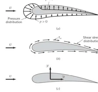
2.1.3 Drag & Lift concept
There are 2 basic categories of aerodynamics forces acting on a road vehicle body which described as below and shown in Figure 2.2:-
1) Shear Stress – which acts parallel to the surface body and contributes to drag, (also known as the component of aerodynamic force parallel to the wind)
2) Pressure – which acts vertically to the surface body and contributes to lift, (also known as the component of aerodynamic force perpendicular to the wind).[7]
Figure 2.2: Forces acting on an Aerofoil
Figure 2.3: Shear force and Pressure acting on the surface body
dFx = ( p dA) cos θ + ( τw dA) sin θ [Eq. 1] dFy = - ( p dA) sin θ + ( τw dA) cos θ [Eq. 2]
Thus, the net x and y component of the force on the object are:
1) Resultant force in the direction of the upstream velocity is termed the drag,D
D= ∫ dFx = ∫ p cos θ dA + ∫ τw sin θ dA [Eq. 3] 2) Resultant force normal to the upstream velocity is termed of lift, L
L = ∫ dFy = - ∫ p sin θ dA + ∫ τw cos θ dA [Eq. 4]
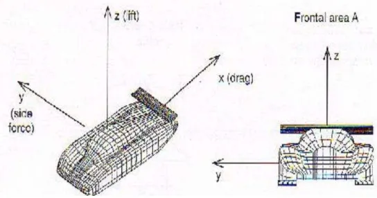
For certain three dimensional (3D) modeled bodies as in Figure 2.4, there might be also side force acting perpendicular to the plane containing Drag and Lift. The resultant force can be divided into 3 components which are moment, drag and lift coefficients but for this study, only drag and lift are to be considered.
vehicle while the vehicle is in traveling mode and it acts externally on the body of the vehicle. The drag force can be measured directly by simply attaching the body subjected to fluid flow, to a calibrated spring and measuring the displacement in the flow direction. Drag force is usually an undesirable effect, like friction and mostly engineers are trying to minimize by creating many devices. Reduction of drag is closely associated with the reduction of fuel consumption in automobiles, submarines and aircraft, improved safety and durability of structures subjected to high winds and reduction of noise and vibration [8]. More sophisticated drag-measuring devices called drag balances uses flexible beams fitted with strain gauges to measure the drag electronically. Besides that, it can be calculated using formulas [Equation 5] as shown below:
DA =
½
ρ v^2 CD A [Eq.5]Where; CD = coefficient of Drag A = frontal area (m2)
ρ = density of air [kg/m3]
v = velocity of vehicle [m/s]
The drag and lift forces depend on the density of the air, the upstream velocity of the wind, and the size, shape, and orientation of the body are among other elements which need to be taken into account. Therefore, it is more convenient to work with appropriate dimensionless numbers that represent the drag and lift characteristic of the body which is the drag coefficient. Modern road vehicles such as cars and MPV’s have the value of coefficient of drag (CD = 0.2 - 0.4) [9]. The smaller the value of CD, the