ANALYSIS OF VIBRATION LEVEL OF A PERFORATED PANEL
USING FINITE ELEMENT METHOD
Wai C. Muna*, Azma Putrab and Ahmad Rivaic Faculty of Mechanical Engineering,
Universiti Teknikal Malaysia Melaka, Hang Tuah Jaya 76100, Durian Tunggal, Melaka, Malaysia. *[email protected], [email protected], [email protected]
Abstract—Introduction of perforation into plat-like structures is commonly found as one of practical noise control mechanisms to reduce the sound radiation. However, introduction of holes into the panel reduces its stiffness and hence increases its vibration. Since the discussion and also the analytical model to quantify this effect is lacking, this paper investigates the dynamics of a perforated panel by using Finite Element Method (FEM). It is found that the size and number of holes determine the frequency range of which the level of vibration increases due to perforation.
Keywords—Mobility; Plate; Perforate; Hole.
I. INTRODUCTION
The vibration of engineering structures, particularly those consisting of thin plate-like members, can be a significant source of noise in many situations. Noise control techniques are often focused on reducing the amplitudes of vibration and include damping treatments, vibration isolation and structural modification. However, it is also possible to reduce the sound radiation of plate-like structures directly by constructing them from perforates. This technique is known to be capable of achieving considerable noise reductions and has found many practical applications, including safety guard enclosures over flywheels or belt drives and product collection hoppers.
However, the effect of the dynamics of the plate after perforation is rarely discussed. The recent models to calculate the sound radiation from a perforated panel also ignore this effect [1, 2]. The investigation of the effect of perforation on dynamic properties of plates began in the early 1960s in order to determine an accurate stress analysis of perforated panels used to support the tubes in a heat exchanger [3]. Soler and Hill [4] proposed an analytical formula to calculate the bending stiffness of a perforated panel as a function of hole geometry. Forskitt et al. [5] used the Finite Element Method (FEM) to obtain the dynamic properties, namely Young’s modulus and Poisson’s ratio of a perforate. The density is calculated based on the fraction of a solid plate. These properties are then used to calculate the natural frequencies. According to Burgemeister and Hansen [6], the model in [5] does not provide correct resonance frequencies. The FEM was again implemented to model the modal response of range of plates with varying perforation geometries. From this, the simulated resonance frequency was compared with that from the FEM model for the solid plate. The results of these comparisons were then fitted to a cubic expression as a general equation for other perforation
geometries which is independent of the mode order of the panel.
As previous models concern with only the dynamic properties, particularly the natural frequency, this paper investigates the change of vibration level due to the introduction of holes into a solid panel. FEM is applied to calculate the mobility of a perforated panel. The mobility of the perforate is then compared against that of the solid plate in one-third octave band frequency.
II. MOBILITY
Mobility is defined as the ratio between the vibration velocity v and the excitation force F given as a function of frequency.
This can also be considered as a ‘transfer function’ assuming the system is linear. For a finite rectangular plate with dimensions ab, the mobility at an arbitrary point (x,y) subjected to a point force F at (x0,y0) is given
wheren is the n-th mass-normalised mode shape of the
structure, nis the n-th natural frequency and is the n-th damping loss factor. A case often considered is n-that of a rectangular plate with simply supported boundary conditions as this system provides a simple analytical solution. For a simply supported rectangular plate with dimensions ab, the mode shape can be represented as sinus functions. This and the natural frequency for mode (p, q) are, respectively stiffness for E is the Young’s modulus, t is the plate
In this report, the level of the panel vibration is presented as the mobility (to normalize the vibration velocity with the input force). The next section discusses the FE model used to calculate the mobility of the perforated plate. Eq. (2) is used to validate the mobility obtained from the FE model for a solid simply supported plate.
III. FINITE ELEMENT MODEL
In this paper, the analysis only considers a perforated panel with rectangular arrangement of holes. The model is developed using PATRAN and NASTRAN software. The simulated samples of perforated panels are determined by varying the perforation ratio with fixed diameter or number of holes and also by varying the diameter and number of holes with fixed perforation ratio. The choice of these parameters is summarized in Tables 1, 2, and 3.
Table 1. Parameters of the perforated panel with fixed hole diameter but
different number of holes and perforation ratios.
Number of holes Diameter (mm) Perforation ratio (%)
40 10 5
80 10 10
160 10 21
Table 2. Parameters of the perforated panel with fixed number of holes
but different hole diameters and perforation ratios.
Number of holes Diameter (mm) Perforation ratio (%)
40 10 5
40 15 12 40 20 21
Table 3. Parameters of the perforated panel with fixed perforation ratio
but different numbers and diameters of holes.
Number of holes Diameter (mm) Perforation ratio (%)
20 20 10 40 14 10 80 10 10
The panels having dimensions of 0.3 0.2 m and thickness 1 mm are assumed simply supported along all the edges. The panels are assumed to be made of steel having Young’s modulus of206.8GPa and density of
-3 kgm 733 .
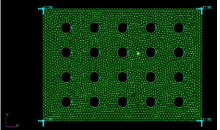
7805 . Figs. 1-7 show the Finite Element (FE) model of perforated panels from PATRAN software with various geometries of holes as in Table 1, 2 and 3.
The mesh element type used in the FE model is the basic two-dimensional triangular element (Tria shape and Paver as the mesher). The total number of elements is generated automatically by the software. However, the
element size must be much smaller than half the structural wavelength corresponding to maximum frequency of analysis to give accurate results at high frequencies. The global edge length of each element is set to be0.005m. An excitation force of 1Nis applied slightly away from the centroid of the panel at co-ordinates (0.18, 0.12) where the (0, 0) is set as the reference co-ordinate. This is to generate the vibration modes as many as possible. The location of the excitation force and the response are the same for each sample for consistency of analysis. The damping coefficient is assumed to be0.03. The vibration level of the panel is analyzed in the frequency range of
Hz 5000
-10 with a frequency step of2Hz.
Figure 1. FE model of a perforated panel with 20 holes
and 20 mm hole diameter.
Figure 2. FE model of a perforated panel with 40 holes
and 10 mm hole diameter.
Figure 3. FE model of a perforated panel with 40 holes
Figure 4. FE model of a perforated panel with 40 holes
and 15 mm hole diameter.
Figure 5. FEA model of a perforated panel with 40 holes
and 20 mm hole diameter.
Figure 6. FEA model of a perforated panel with 80 holes
and 10 mm hole diameter.
Figure 7. FEA model of a perforated panel with 160 holes
and 10 mm hole diameter.
IV. RESULTS AND ANALYSIS
Fig. 8 shows the validation of the mobility of a solid panel from the FE model with that from the analytical model using Eq. (2) with dimensions and properties as mentioned in Section III. For the latter, the calculation involves all modes for index p40 and q40 to ensure they are generated up to 5 kHz.
This comparison is also to ensure that the FE model used is valid in terms of the meshing size, setting of boundary conditions, etc. It can be seen that the results between the models are in good agreement up to 5 kHz.
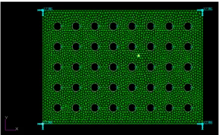
Fig. 9 presents the effect of the perforation ratio on the perforated panel mobility as in Table 2. The results are plotted in one-third octave bands for ease of analysis. It can be seen that the mobility increases as the perforation ratio is increased particularly around the off-resonance peak between 200-1000 Hz and also above this frequency range. This effect can also be observed below the fundamental frequency at 80 Hz.
Below the fundamental frequency where the structural wavelength is much larger than the hole separation distance, the vibration amplitude is controlled by the mass of the panel. Introducing the perforation reduces some of the panel mass and therefore increases the mobility at this frequency range. As at high frequency where the structural wavelength is much shorter than the hole separation distance, the effect of perforation is controlled by the bending stiffness. As discussed in [5], there needs a correction for the reduced Young’s modulus relating to the reduction of the elasticity of a perforated panel which reduces the natural frequency of the panel. In this case, it can be seen this also increases the vibration amplitude.
The effect of increasing the perforation ratio is also shown in Fig. 10. This is for the case as in Table 1. The same phenomenon can be seen between the resonance peaks from 200-1000 Hz. The mobility also increases below the fundamental frequency and at high frequency above 1000 Hz.
Fig. 11 shows that by retaining the perforation ratio while varying the number and diameter of holes (see Table 3), the mobility of the perforated plate is not affected.
Figure 8. Comparison of the mobility of a solid panel from FE model
and from analytical calculation.
101 102 103
10-3 10-2 10-1 100
frequency[Hz]
M
o
b
ilit
y
[
d
B
r
e
1
m
/N
s
]
Figure 9. The mobility of perforated panels with 10 mm hole diameter
and different number of holes in one-third octave bands.
Figure 10. The mobility of perforated panels with 40 holes and different
hole diameters in one-third octave bands.
Figure 11. The mobility of perforated panels with different number of
holes and different hole diameters in one-third octave bands.
For convenience of analysis, it is of interest to see the amount of mobility level increased due to perforation. This can be expressed with ‘the effect of perforation’ in dB unit by
s p Y Y
X 10 log10 (5)
where Yp is the mobility of the perforated plate and Ys is for the solid plate.
Figs. 12 and 13 show that the mobility only increases at certain narrow frequency indicated by the fluctuation of
X. The increment at off-resonance peak can be obviously
seen at 400 and 800 Hz. It can also be seen that X becomes larger as the perforation ratio increases. The level is below 5 dB in the present case and this depends on the amount of perforation.
Figure 12. The effect of perforation for 10 mm hole diameter with
different number of holes.
Figure 13. The effect of perforation for 40 holes with
different hole diameters.
Figure 14. The effect of perforation for 10% perforation with different
number and hole diameters.
Fig. 14 clearly shows that only the perforation ratio affects the mobility of the panel, not the hole size or number. Although below 80 Hz and at 400 Hz introduction of larger holes can be seen to increase the mobility, the increment is small and can be ignored.
V. CONCLUSION AND RECOMMENDATION
The vibration amplitude (represented by mobility) of perforated rectangular plates with varying hole geometries has been calculated by using the Finite Element Method. It is found that the mobility increases as the perforation ratio increases. The effect of perforation is mainly between the resonant frequencies of the plate. For fixed perforation ratio, the hole size and number have negligible effect on the perforated plate mobility.
as well as the arrangement of the holes in real engineering structures may vary. Therefore, future works can focus on analyzing the effect of geometrical factor and arrangement of holes on the mobility of the perforates. The arrangement of holes can be uniform or non-uniform and symmetrical or non-symmetrical. The experimental findings would be of interest to support the analysis.
ACKNOWLEDGMENT
The authors would like to acknowledge the Universiti Teknikal Malaysia Melaka (UTeM) for supporting the present work through research funding from Short Term Grant PJP/2010/FKM(33B)S747.
REFERENCES
[1] A. Putra and D. J. Thompson, Sound radiation from perforated plates, Journal of Sound and Vibration, 329 (2010), 4227-4250.
[2] A. Putra and D. J. Thompson, Sound radiation from perforated and unbaffled plates near a reflecting rigid surface, Journal of
Sound and Vibration, 330 (2011), 5443-5449.
[3] R. Bailey and R. Hicks. Behavior of perforated plates under plane stress. Journal of Mechanical Engineering Science, 2 (1960), 143–161.
[4] A. I. Soler and W. S. Hill. Effective bending properties for stress analysis of rectangular tubesheets. Transactions of the ASME: Journal of Engineering for Power (1977), 365-370. [5] Forskitt, J. R. Moon, and P. A. Brook. Elastic properties of
plates perforated by elliptical holes. Applied Mathematical
Modelling, 15 (1991), 182–190.
[6] K. A. Burgemeister and C. H. Hansen. Calculating resonance frequencies of perforated panels. Journal of Sound and
Vibration, 196 (1996), 387–399.
[7] P. Gardonio and M. J. Brennan. Moblity and Impedance Methods in StructuralDynamics, Chapter 9 in Advanced
Applications in Acoustics, Noise and Vibration(Eds. F. J. Fahy