UNIVERSITI TEKNIKAL MALAYSIA MELAKA
Reverse Engineering of A Pharmaceutical
Bottlepack Cap By Plastic Injection Mould
Thesis submitted in accordance with the partial requirements of Universiti
Teknikal Malaysia Melaka for the Bachelor of Manufacturing Engineering
(Manufacturing Design)
By
Siti Rafidah Bt Mamat
Faculty of Manufacturing Engineering
SULIT
TERHAD
√ TIDAK TERHAD
(Mengandungi maklumat yang berdarj ah keselamat an at au kepent ingan Malaysia yang t ermakt ub di dalam AKTA RAHSIA RASMI 1972)
(Mengandungi maklumat TERHAD yang t elah dit ent ukan oleh organisasi/ badan di mana penyelidikan dij alankan)
(TANDATANGAN PENULIS)
* Tesis dimaksudkan sebagai t esis bagi Ij azah Dokt or Falsaf ah dan Sarj ana secara penyel idikan, at au disert ai bagi pengaj ian secara kerj a kursus dan penyel idikan, at au Laporan Proj ek Sarj ana Muda (PSM). ** Jika t esis ini SULIT at au TERHAD, sil a l ampirkan surat daripada pihak berkuasa/ organisasi berkenaan
BORANG PENGESAHAN STATUS TESIS* UNIVERSITI TEKNIKAL MALAYSIA MELAKA
JUDUL: REVERSE ENGINEERING OF PHARMACEUTICAL BOTTLEPACK CAP BY USING PLASTIC INJECTION MOULD.
SESI PENGAJIAN: 2006/ 2007
Saya ____________________SITI RAFIDAH BT MAMAT ______________________
mengaku membenarkan t esis (PSM/ Sarj ana/ Dokt or Falsaf ah) ini disimpan di Perpust akaan Universit i Teknikal Malaysia Melaka (UTeM) dengan syarat -syarat kegunaan sepert i berikut :
1. Tesis adalah hak milik Universit i Teknikal Malaysia Melaka.
2. Perpust akaan Universit i Teknikal Malaysia Melaka dibenarkan membuat salinan unt uk t uj uan pengaj ian sahaj a.
3. Perpust akaan dibenarkan membuat salinan t esis ini sebagai bahan pert ukaran ant ara inst it usi pengaj ian t inggi.
4. **Sila t andakan (√)
APPROVAL
This thesis submitted to the senate of UTeM and has been accepted as partial fulfillment of the requirements for the degree of Bachelor of Manufacturing Engineering (Manufacturing Design). The members of the supervisory committee are as follow:
………. Mr Hassan B Attan
DECLARATION
“I hereby declare that this report and its entire contents is my own work unless specific reference and figure are made in the text. This work is submitted in partially fulfillment of the Bachelor in Manufacturing Design and has not been
submitted for any other qualification in any other institute.
Signature : ………..
Author’s Name : Siti Rafidah Bt Mamat
ABSTRACT
ABSTRAK
DEDICATION
Specially dedicated to; my beloved father, Mamat Bin Awang Teh and my mother,
Halimah Bt Mamat who are very concern, understanding, patient and supporting.
Thanks for everything. To my sisters, brothers and all my friends, I also would like to
ACKNOWLEDGEMENTS
In The Name of Allah Almighty And The Most Merciful and Blessings Be Upon His Messenger Prophet Muhammad S.A.W and His Companions.
I am thankful to Allah the almighty for his divine inspirational guidance, which had helped me in completing this final year project. I would like to convey my sincere thanks to my first supervisor, Mr. Hassan B Attan and second supervisor, Mr Zolkarnain B Marjom for their constructive guidance and patience in fulfilling our aspiration in completing this project. I would like to thanks to technicians involved; Mr. Jaafar B Lajis, Mr. Nor Fauzi B Tamin and Mr. Hairmi B Othman for their explanation, experiment and demonstration of the lab equipments regarding to this lab work. Finally, to my family and friends for their support and understanding during the completion this final year project report.
TABLE OF CONTENTS
1.1Introduction Of the Research…….………....1
1.2 Objective of the Research…..……….…1
1.3 Scopes of Study ……….2
1.4 Problem Statement………..2
1.5 Research Organization………...2
2. LITERATURES REVIEW………...4
2.1 Introduction ……….…….…………...………..4
2.2 Reverse Engineering………4
2.3 Bottle Pack Cap………...7
2.4 Plastic Injection Molding……..………...7
2.5 Mold………...9
2.6 Measurement Equipment in Reverse Engineering………...……….10
2.6.1 Coordinate Measuring Machine (CMM)…..………..….……….…...10
2.6.2 Vernier calliper………..………..13
2.6.3 Optical Comprator………..……….14
2.6.4 3D Scanner……….………...….15
2.7 Software In Reverse Engineering………..………17
2.7.1 Solidworks………...17
2.7.3 MoldflowXpress………..18
2.7.4 Mold Design………19
2.7.5 NX Mold Design……….21
2.8 Process In Reverse Engineering………...……….23
3. METHODOLOGY O F THE REVERSE ENGINEERING FOR THE PART DESIGN 3.1 Introduction………26
3.2 Method for the Research………27
3.3 Process Flow…………..… ……….………..28
3.4 Measurement Equipment………...29
3.4.1 Coordinate Measuring Machine (CMM)……….……….29
3.4.1.1 Introduction to CMM………….……… ……...29
3.4.2 Optical Comparator……….…..31
3.4.2.1 Introduction of Optical Comparator………...…….….31
3.4.2.2 Optical Comparator procedure………...………..…32
3.5 Drawing Software………..34
3.5.1 Drawing Procedure………34
3.5.2 Introduction Of Solidworks……….………..34
3.5.3 Procedure Of Solidworks..……….………..….34
3.5.3.1 Sketcher ………..…...……….35
3.7 Core and Cavity Design………41
3.7.1 Cavity Design………42
3.7.2 Core Design………...…43
3.7.3 Differential between Two Injection Mold Machine………….…….…...48
3.7.3.2 Nissie Injection Mold Machine………...…..49
4. ANALYSING THE PROCESS OF REVERSE ENGINEERING………..……....51
4.1 Introduction………..……51
4.2 Analysis on the injection time required……….….………..………52
4.2.1 Identify the Result………..………55
4.2.2 Part Geometry (Wall Thickness)………….………..……….55
4.2.3 Injection Location…,..……….….……..56
4.2.4 Selecting New Material………..………..…….56
4.2.4.1 Concept Of Selecting Materia l………...…..………...56
4.2.4.1.1 Concept 1………...57
4.2.4.1.2 Concept 2………..………...………..57
4.2.4.1.3 Concept 3………...………58
4.2.4.1.4 Concept 4………...………....58
4.2.4.2 Concept Selection………… ………..…………...……..59
4.2.4.2.1 Pugh’s Concept Selection Method………...….59
4.2.4.3 Change the Process Condition………… ……….…………...61
APPENDICES
A Gantt Chart PSM 1 and PSM 2
B List of the dimensions taken using Optical Comparator C Injection time results for different materials
D HDPE Properties And Application E Bottlepack Cap Orthographic View F Assembly Drawing
G Isometric View
LIST OF FIGURES
NO Name of Figure Page
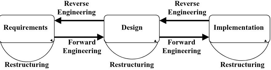
2.1 Relationship between the re-engineering term 5
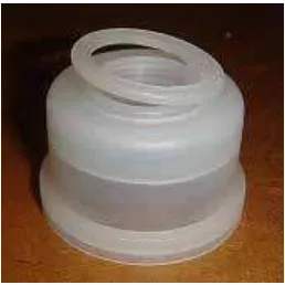
2.2 Bottlepack Capr 7
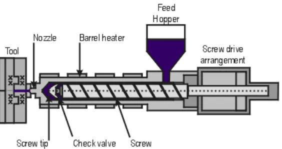
2.3 Injection molding system 9
2.4 Coordinate measuring machine Wenzel LH 54 11
2.5 Coordinate measuring machine system 12
2.6 Part of the vernier caliper 14
2.7 Vernier caliper 14
2.8 Optical Comparator 15
2.9 3D scanner 17
2.10 MoldflowXpress 19
2.11 Core and cavity 20
2.12 Mold product 22
2.13 Injection time. 22
2.14 Process in reverse engineering. 23
3.1 Measured for angle plane measurements 31
3.2 Optical Comparator 32
3.3 Part of Optical Comparator 33
3.4 Sketch circle 35
3.5 Circle and Dimension 36
3.6 Extrude Process 37
3.7 Extrude Cut Process 37
3.8 Fillet Process 38
3.9 Before revolve cut process 39
3.10 Revolve cut process 39
3.11 After revolve cut process 39
3.12 Plane 40
3.13 Finish Product 40
3.15 Core of Bottlepack cap 42
3.25 Complete design of core and cavity 47
3.26 Arburg Injection Mold Machine 48
3.27 Nissie Injection Mold Machine 50
4.1 Injection Location of the Product 53
4.2 Result of the Injection Molding Process 53
4.3 The result for the actual data 54
4.4 The condition of Actual Data 54
4.5 The result for the actual data 62
4.6 The condition of Actual Data 62
4.7 The result of Recommended Data 63
LIST OF TABLES
2.1 The specifications of the CMM Wenzel LH 54 12
2.2 The Description from the journal /book collection involving
to Injection Molding 24
3.1 The specifications of the CMM Wenzel LH 54 30
3.2 General specification for Mitutoyo Optical Comparator 33
3.3 The specification of the Arburg injection molding machine 49
3.4 The specification of the Nissie injection molding machine 50
CHAPTER 1
INTRODUCTION
1.1 Introduction of the Research
The main purpose of this research is to design a new mold by reverse- engineering the existing product. By applying the reverse engineering method, some of the costs like manufacturing costs and assembly costs are can be reduced easily. By using some a low cost of CAD/CAM applications and conventional measuring tools the cost designing will reduce. The reverse engineering is used to design the bottlepack cap. Besides that, the other main process to complete the bottlepack cap product is desiging the core and the cavity of the mold. The mold will be used for the injection molding machine in producing the finished product. This study is focused on the methodology and application of reverse engineering in producing the actual methodology product such as bottlepack cap.
1.2 Objective of the Research
second objective is to apply the equipment and software into the reverse engineering process. The third objective is to know how to make of the core and cavity by using the suitable software, and the function of this part. And the final objectives are to analyze the product and produce the new mold of the bottlepack caps.
1.3 Scope of the Study
The problem statement of this project is how to apply the reverse engineering method to analyze the aspect of the product requirement during the manufacturing process, the process and methods of reverse engineering and determine the actual data obtained and study the possibilities of producing a similar mold with a similar function by using the moldflowExpress. Beside that, to design the product,the equipment and software to be use must be identified.
1. 4 Problem Statement
Ain Medicare is a pharmaceutical company producing product for medical use. One of the products is bottlepack cap. Ain Medicare is producing the mold using one injection molding to support the production if need to outsource to meet the demand.The project is an attempt to support the production at Ain Medicare by produce the mold of the same product to be used on UTeM injection mold machine.
1.5 Research Organization
application, scopes of study, problem statements, project organization, conclusion and the main focus and also the method that are going to be use to complete this research. In chapter two, it explains about the literature review of the reverse engineering, plastic injection mold, the equipment and the software that are used in reverse engineering. Besides that, this research also includes about the literature review of the original bottlepack cap product that has been produced by Ain Medicare Sdn.Bhd. This chapter also explains about the sources that related to the reverse engineering, plastic injection and the making of core and cavity. Chapter three is the methodology, which shows how the process of reverse engineering and plastics injection mold has being applied according to the equipments and methods used. It is also summarized some of the processes and applications that have been applied in reverse engineering. By taking some of the examples and guidance from other researches, then it can be studied and applied in this research.
CHAPTER 2
LITERATURE REVIEW
2.1 Introduction
In this chapter explain about historical and the meaning of the reverse engineering and the application of the reverse engineering. Reverse engineering is important to produce the new pattern of the product by using reverse engineering equipment. In this chapter also explain about the software will be using to design the product. Beside that, it also include about the mold making and the application of plastic injection mold. At the last of this chapter, all the literature review about the reverse engineering, software is used to produce the product. Lastly the step to produce mold making can be studied. In the end of this research, it can summarize about the application of the reverse engineering in the manufacturing field.
2.2 Reverse Engineering
Reverse engineering process is a unique technique that uses the existing entity information to produce a new entity that has some of same properties of the existing entity.:( Saedon, J., Che Abdullah,S, Ismail,A R and Yahaya M A ,2006)
Figure 2.1 : Relationship between the re-engineering term.; (Gannod,G.C ,2000)
Reverse engineering defined as the process of duplicating an existing component, subassembly, or product, without the aid of drawings, documentation, or computer model is known as reverse engineering.
Reverse engineering can be viewed as the process of analyzing a system to: 1. Identify the system's components and their interrelationships
2. Create representations of the system in another form or a higher level of abstraction
3. Create the physical representation of that system
Reverse engineering is very common in such diverse fields as software engineering, entertainment, automotive, consumer products, microchips, chemicals, electronics, and mechanical designs.
Another reason for reverse engineering is to compress product development times. In the intensely competitive global market, manufacturers are constantly seeking new ways to shorten lead-times to market a new product. Rapid product development (RPD) refers to Requirements Design Implementation
Reverse
recently developed technologies and techniques that assist manufacturers and designers in meeting the demands of reduced product development time. For example, injection-molding companies must drastically reduce the tool and die development times. By using reverse engineering, a three-dimensional product or model can be quickly captured in digital form, re-modelled, and exported for rapid prototyping/tooling or rapid manufacturing.
Following are reasons for reverse engineering a part or product:
1. The original manufacturer of a product no longer produces a product 2. There is inadequate documentation of the original design
3. The original manufacturer no longer exists, but a customer needs the product 4. The original design documentation has been lost or never existed
5. Some bad features of a product need to be designed out. For example, excessive wear might indicate where a product should be improved
6. To strengthen the good features of a product based on long-term usage of the product
7. To analyze the good and bad features of competitors' product
8. To explore new avenues to improve product performance and features
9. To gain competitive benchmarking methods to understand competitor's products and develop better products
10. The original CAD model is not sufficient to support modifications or current manufacturing methods
11. The original supplier is unable or unwilling to provide additional parts
12. The original equipment manufacturers are either unwilling or unable to supply replacement parts, or demand inflated costs for sole-source parts
13. To update obsolete materials or antiquated manufacturing processes with more current, less-expensive technologies
In doing so, it uncovers as much information as possible about the design ideas that were used to produce a particular product.
2.3 Bottlepack Cap
Bottlepack cap is one of the product is produce at Ain Medicare Sdn Bhd. The function of the bottlepack cap is to cover the Intravenous Solution bottle. The bottlepack cap product produces by using the injection molding machine. Each time during operation the machine will produce eight caps. The injection molding at the Ain Medicare used 4 plate mold of core and cavity.
Figure 2.2 : Bottlepack cap
2.4 Plastic Injection Mold
injection molding injects the material (polypropylene) into the core and cavity. This versatile process allows us to produce high quality, simple or complex components on a fully automated basis at high speed with materials that have changed the face of manufacturing technology.
Plastic injection moulding is a manufacturing technique for making parts from thermoplastic material. Molten plastic is injected at high pressure into a mold, which is the inverse of the desired shape. The mold is made by a moldmaker (or toolmaker) from metal, usually either steel or aluminium, and precision-machined to form the features of the desired part. Injection moulding is very widely used for manufacturing a variety of parts, from the smallest component to entire body panels of cars. It is the most common method of production, with some commonly made items including bottle caps and outdoor furniture. There are the four major categories must be consider during the plastic injection molding process. There are temperature, pressure, time, and distance.;(Bryce,D.M ,1997)
Figure 2.3 : Injection molding system Boothroyd, G, Dewhurst, P and Knight, W (2002)
An injection molding system consists of the machine and mold for converting, processing and forming raw thermoplastic material, usually in the form of pallets, into a part of desired shape and configuration. Figure shows a schematic view of a typical injection molding system. The major components of an injection molding system are the injection unit, the clamp unit, and the mold : (Boothroyd, G, Dewhurst, P and Knight, W 2002)
2.5 Mold
Considerable thought is put into the design of molded parts and their moulds, to ensure that the parts will not be trapped in the mould, that the moulds can be completely filled before the molten resin solidifies, to compensate for material shrinkage, and to minimize imperfections in the parts, which can occur due to peculiarities of the process.