I MODELLING FOR PREDICTION AND OPTIMIZATION OF
MECHANICAL RESPONSE OF UNEQUAL THICKNESS STEEL SHEET
RESISTANCE SPOT WELDS IN TENSILE-SHEAR LOADING CONDITION
HARESHWARA RUBAN A/L SUBRAMANIAM
I SUPERVISOR DECLARATION
“I hereby declare that I have read this thesis and in my opinion this report is sufficient in terms of scope and quality for the award of the degree of
Bachelor Of Mechanical Engineering (Design and Innovation)”
Signature : ………..
Supervisor: DR. S. THIRU CHITRAMBALAM
II MODELLING FOR PREDICTION AND OPTIMIZATION OF MECHANICAL RESPONSE OF UNEQUAL THICKNESS STEEL SHEET RESISTANCE SPOT
WELDS IN TENSILE-SHEAR LOADING CONDITION
HARESHWARA RUBAN A/L SUBRAMANIAM
This thesis is submitted to Faculty of Mechanical Engineering in partial fulfilment of the requirement for the award of Bachelor’s Degree in
Mechanical Engineering (Design and Innovation)
Faculty of Mechanical Engineering Universiti Teknikal Malaysia Melaka
I DECLARATION
“I hereby declare that the work in this report is my own except for summaries and quotations which have been duly acknowledge”.
Signature: ………..
Author: HARESHWARA RUBAN A/L SUBRAMANIAM
III ACKNOWLEDGEMENT
I would like to take this opportunity to thank and express my gratitude to my beloved supervisor DR. Thiru Chitrambalam for his guidance and support in helping me in making this project a success one. His advices, comments, suggestions and tolerance are so helpful and without him, I would have faced lots of difficulties to complete my Final Year Project.
Not forgetting, my friends, especially Premawathi, Tham Kar Mun, Sean John Mathew and Tan Beng Hong who have supported me in various ways to ensure all my activities of this Final Year Project went smoothly according to the schedule.
IV ABSTRAK
V ABSTRACT
VI TABLE OF CONTENTS
CHAPTER TITLE PAGE
DECLARATION... I
ACKNOWLEDGEMENT... III
ABSTRAK ...IV
ABSTRACT ... V
LIST OF FIGURES ...IX
LIST OF TABLES ... X
LIST OF ABBREVIATIONS ...XI
LIST OF SYMBOLS ... XII
LIST OF APPENDICES ... XIII
CHAPTER 1 ...1
INTRODUCTION ...1
1.1 Background ... 1
1.2 Problem Statement ... 1
1.3 Objectives... 2
1.4 Scope ... 2
CHAPTER 2 ...3
LITERATURE REVIEW ...3
2.1 An Overview of Resistance Spot Welding ... 3
2.2 Formal Welding Procedure Control ... 4
2.3 Resistance Welding Description ... 5
2.4 Surface Cleaning ... 7
2.5 Welding of Dissimilar Metals ... 9
2.6 Electrothermal Process of Welding... 9
2.7 Resistance Spot Welds Parameters ... 10
2.8 Testing and Inspection ... 12
VII
METHODO LOGY... 13
3.1 Background ... 13
3.2 Introduction ... 13
3.3 Methodology Flow ... 14
3.4 Determining the Design of Experiment (DOE) ... 15
3.5 Common design types ... 15
3.6 Response Surface Methodology ... 16
3.7 Materials... 19
3.8 Welding Machine and Electrode... 19
3.9 Conducting Experiments... 21
3.10 Specification of Resistance Spot Welding Machine ... 22
3.11 Weldability Testing Approach ... 22
3.12 Tensile-Shear Testing Procedure ... 23
3.13 Stress Analysis and failure Load ... 23
CHAPTER 4 ...25
EXPERIMENTAL PROCEDURE ... 25
4.1 Design of Experiment ... 25
4.2 Materials Preparation ... 28
4.3 Experiment Setup ... 28
4.4 Procedure for mechanical testing ... 28
CHAPTER 5 ...29
MODELS SELECTION AND RESULTS ... 29
5.1 Selection of a mathematical model ... 29
5.2 Development of model... 30
5.3 Central Composite Design ... 30
5.4 Response Surface Regression ML versus A, B, C, D ... 31
5.1 Graphs ... 34
CHAPTER 6 ...47
DISCUSSION ... 47
6.1 Discussion for Maximum Tensile Strength ... 47
CHAPTER 7 ...52
CONCLUSIONS AND RECOMMENDATION ... 52
VIII
7.2 Recommendation ... 54
BIBLIOGRAPHY ...55
APPENDICES ...57
A GANTT CHART... 57
IX LIST OF FIGURES
No. TITLE PAGE
Figure 1.1 Resistance Spot Welding ... 1
Figure 2 1 Resistance Weld Cycle ... 6
Figure 2 2 Specimen Soaked under alcohol... 9
Figure 5 1 Histogram ... 34
Figure 5.3 Surface Plot of Maximum Tensile Strength against weld current and weld time... 36
Figure 5.4 Surface Plot of Maximum Tensile Strength against weld current and thickness... 37
Figure 5.5 Surface Plot of Maximum Tensile Strength against electrode force and weld time... 38
Figure 5.6 Surface Plot of Maximum Tensile Strength against weld current and thickness... 37
Figure 5.7 Contour Plot of weld current and ... 37
Figure 5.8 Contour Plot of weld current and electrode force ... 40
Figure 5.9 Contour Plot of weld current and weld time ... 42
Figure 5.10 Contour Plot of weld current and thickness ... 43
Figure 5.11 Contour Plot of electrode force and weld time ... 43
Figure 5.12 Contour Plot of electrode force and thickness ... 43
Figure 6 1 Comparison between Maximum Load and Expected Maximum Load .... 49
X LIST OF TABLES
No. TITLE PAGE
Table 3.1 Order of matrix design ... 17
Table 3.2 Design of matrix using minitab software... 18
Table 5.1 Central composite design ... 30
Table 5.2 Two- level factorial: Full factorial ... 31
Table 5.3 Estimated Regression Coefficients for ML ... 31
Table 5.3 Estimated Regression Coefficients for UTS ... 31
Table 6 1 Results of Maximum load value and predicted maximum load value ... 48
XI LIST OF ABBREVIATIONS
ASTM = American Society of Testing and Material AWS = American Welding Society
RSM = Response Surface Methodology DOE = Design of Experiment
DOM = Design of Matrix HAZ = Heat Affected Zone
XII LIST OF SYMBOLS
I = Current (in Ampere) Σ = Strain Stress
K = Heat losses Factor R = Resistance (in Ohm)
XIII LIST OF APPENDICES
No. TITLE PAGE
A Gantt Chart………...27
1 CHAPTER 1
INTRODUCTION
1.1 Background
Welding and joining have becoming more essential for the manufacturing industries and also for the structural fabrication, which may vary very large structures such as big ships and bridges, to very complex structures such as air craft engines or miniature components for micro-electronic application. (Norrish, 2006).
While these industries involve welding large components or structures, welding of thin strips, foils, wire and components are also widely used. Furthermore, these welding techniques are widely used in metal surfacing by welding processes where it is applies to several components in various industries for improving wear and corrosion resistance.
Welding processes, with modifications of operating conditions are also can be used to cut materials such as gas torch, metal arc, plasma arc and electron beam. In addition, welding processes can be classified into two categories:
i. Fusion Welding
1 i. Fusion Welding
In fusion welding, actual melting of the metal is involved in forming the bond. Examples are gas welding and arc welding processes.
ii. Solid state or non-fusion welding.
In solid state welding, heat energy and pressure is applied to the work pieces to be joined and bonding occurs primarily due to diffusion of atoms and intimate contact of clean surfaces. No melting process is involved. Examples are cold welding, diffusion bonding and friction welding (Srinivasan, 2008).
As early 19 century Elihu Thompson originated resistance spot welding (RSW) and he also stated that resistance spot welding follows the basic principles as follows;
“Resistance spot welding requires a transformer with the primary is and secondary is connected to its own specified cables. Both of cables which ends should be connected
tightly by using clamps that will also hold the specimen of metals which will be welded
together to hold firmly. Heavy current will pass through the joints and create such a huge heat to melt those metals to be combined as one”. (COMPTON, 1939)
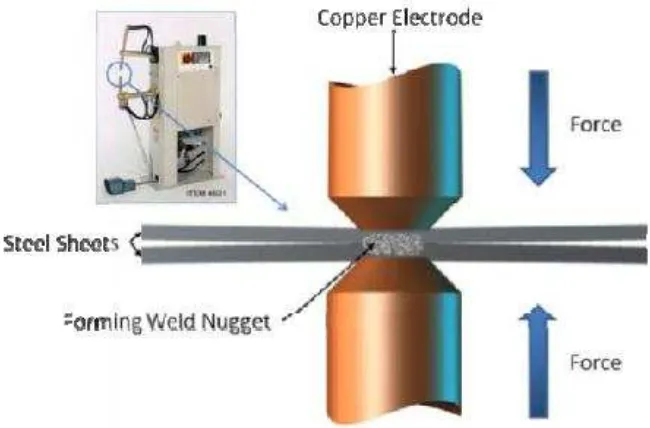
Figure 1-1 Resistance Spot Welding
1 For past several decades, Figure 1.1 resistance spot welding process has been widely used in fabricating sheet metals. Resistance spot welding is also inexpensive and effective way to join two metals. It is a process where metal surfaces are joined together by going through heat that is obtained due the resistance of electric current flow. These spot welds can be operate completely automated. There are three main stages involves in the resistance spot weld; the foremost is the squeeze time, followed by weld time and hold time.
Furthermore, this process are highly demanding in the automobile manufacturing industry whereby most common application is to weld the sheet metal to form a car. This process helps the automobile industry in achieving higher strength and also the productivity in manufacturing and repair. There is estimation that an ordinary car may contain 3000 to 5000 resistance spot welds, the common thicknesses will be in a range about 3mm (N. Athi, S.R. Wylie, J.D Cullen, A.I. Al-Sharma, 2009)]. It is must to evaluate the strength of those welded thin sheet metals in dynamic loading conditions to determine the optimum welding condition to help cutting down the cost, time and also materials. By determining the optimum welding condition may enhance the safety features in the automotive industry.
1.2 Problem Statement
2
1.3 Objectives
1. To investigate and study the relationship between the process variables and mechanical response during resistance spot welding of unequal thickness steel sheets to develop mathematical models.
2. To predict, compare the develop model for optimization of mechanical responses.
1.4 Scope
1. To study, understand the theory and controlling of mechanical response of resistance spot dissimilar welds.
2. To apply design of experiment methodologies to develop mathematical models for prediction of responses and optimization.
3 CHAPTER 2
LITERATURE REVIEW
2.1 An Overview of Resistance Spot Welding
The resistance welding processes are commonly classified as pressure welding processes although they involve in a fusion welding at the interface of material being joined. Resistance spot, seam and projection welding rely on a similar mechanism. The specimen will be clamped in a certain force in between two electrodes and a high current is applied. Resistance heating at the contact surfaces causes local melting and fusion. A huge current is supplied for a certain duration (in micro seconds) and pressure is applied to the electrodes before the application of current and for a short time has ceased the flow.
4 Features of the basic resistance welding process include:
i. The process of resistance spot welding needs a basic equipment. ii. The system used can be manipulated manually and automated.
iii. The weldmend is strong enough for relatively long runs of production.
The major applications of the process have been in the joining of sheet steel in the automotive industries. (S.H. Lin, J. Pan, S.R. Wu, T. Tyan, P. Wung, 2002)
2.2 Formal Welding Procedure Control
2.2.1 Selection of welding process
The process can be choose according to the material which will be used, the thicknesses and also the welding position. In most cases certain processes will meet the fundamental requirement of the application and the end choice is depends on the practical consideration (availability of equipment and operators). The choice of process will determine the number of control parameters which need to be considered and the nature of the control relationships. Computer software designed to simplify welding procedure selection.
2.2.2 Determine of welding parameters
5 2.2.3 Assessment of joint performance
In order to test whether the procedure will produce the required joint characteristic, it will be necessary to carry out mechanical and non-destructive examination of sample welds which are made with the specified welding parameters (Norrish, 2006).
2.3 Resistance Welding Description
As stated earlier, in resistance spot welding heat generated through the electric resistance offered at the joint to a high current and sufficient pressure is also applied during the welding process. The amount of heat generated can be calculated from the formula:
H = I2 R T
H = heat generated (J) joules I = Current (A) Amperes R = Resistance (Ohm) T = Time (s) second
(N. Athi, S.R. Wylie, J.D Cullen, A.I. Al-Sharma, 2009)
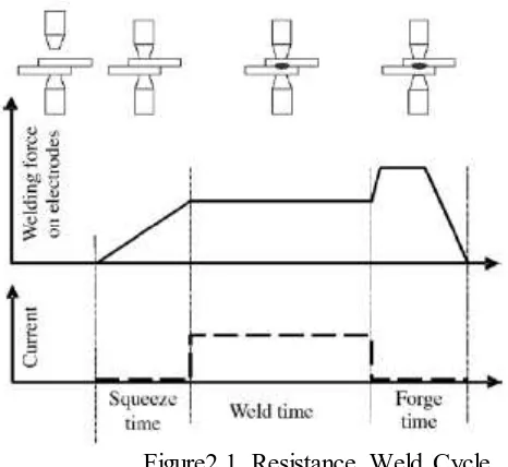
6 1. Approach stage
2. Welding stage 3. Forging stage 4. Pause
Figure 2.1 shows the relationship between force, current and time during a weld cycle. During the first stage, the force is slowly increased. In the second stage, current is applied for a specified duration. The force may slightly decrease due to the metal becoming softer and reaching the fusion point. After this, the current is shut off and additional force is applied. This is the third, forging stage. The pressure is held till the metal is cooled. Then the force is removed. There is a pause period before the next stage is started.
: Figure2.1 Resistance Weld Cycle