DOI: 10.12928/TELKOMNIKA.v12i3.91 549
Simple Hawt Prototype
Efficiency at Small Scale Wind
Speed
Melda Latif1, Mumuh Muharam2, Yonggi Puriza3, Gusriwandi4 1,2
Basic Electrical Engineering Laboratory, Department of Electrical Engineering, Faculty of Engineering, University of Andalas, Indonesia
3
Department of Electrical Engineering, Faculty of Engineering, University of Andalas, Indonesia 4
Department of Mechanical Engineering, Faculty of Engineering, University of Andalas, Indonesia
email : [email protected], [email protected], [email protected],
Abstract
Nowadays, the wind energy research for alternatif anergy has been progress. Wind energy can be found if the wind turbine is available.This paper explains small scale of Horizontal Axis Wind Turbine (HAWT) prototype by using 200 ohm resistor and LED at small scale wind speed. The blade material is acrilic. This material property is light, no easy broken, no corrosive and easy to find it. The blade model is flat plate section. Rotor diameter is 1 meter. The research was did at the beach. Permanent magnet synchronous generator is used to change wind energy to electric energy. The result shows that the generator increase linearly with wind speed. Measured wind speed was 1.9 m/s to 3.9 m/s. Average efficiency of HAWT prototype was 6.2% at delta connected load and 3.7% at wye connected load.
Keywords: HAWT prototype, flat plate blade model, efficiency
1. Introduction
One of the most promosing alternative energies as renewable energy is wind energy which has abundant and free resource. Many researchers have been studying the wind speed characteristics and its potential as a wind turbine generation (WTG) in many countries worldwide [1]. Indonesia which is an archipelagous country has potential wind for developing wind turbine generation (WTG). Unfortunately, Padang, which is a beach city in Indonesia, has wind speed at low rate scale (≤ 7 m/s) [2]. To capture this small scale wind speed, it is needed some technologies in wind turbines for getting higher efficient energy convertion from mechanical energy to electrical energy. From the literatures, it is known that the maximum efficiency is generated by wind energy is about 53% [3],[4]. Although the resulting efficiency is small, but the research related to the utilization of wind energy as an alternative energy source continues to grow.
As the general form of wind turbines, Horizontal Axis Wind turbines (HAWT) are still built even though the dimension of rotor blade become disadvantages. The first disadvantage, the effect on turbine blade crossed by wind cause the vibration and deformation give additional stress and influence the strength of the blade [5]. Another disadvantage, due to the large rotor blade fault, several accidents and also other incidents happened not only in UK [6] but also in other countries [7].
In this paper, to anticipate the disadvantages of the large scale wind turbine, the small scale wind turbine is proposed with some policies. First, the prototype should be able to harvest energy at low speed of wind [1],[8],[9]. Second, the built wind turbine should be applicable for rural or residence utility. Finally, considering the first and second policy, the turbine should be built by using cheap materials and also it needs just small space for installation [10].
2. Research Method
Wind power is the energy per unit of time, then:
. . (2)
. . (3)
where:
PT = mechanical power in the moving air (Watt)
Cp = power coefisient, Cp < 0,6
= air density ( kg/m3)
A = area swept by the rotor blades (m2) = v = wind speed (m/s)
The performance of the HAWT prototype was also determined from the tip speed ratio.Tip speed ratio is the outermost side speed comparison of the rotor against the wind speed. Equation tip speed ratio is:
tsr = .π.D/60/v (4)
where: = shaft speed (rpm) π = 3.14
D = rotor diameter oh the blade (m) v = wind speed (m/s)
the tsr was selected among the 5 s/d 8.
2.1 Blade Design
The material used for the manufacture of the blade is acrilic. Reasons for choosing this material because it was easy, lightweight and not prone to corrosion. The radius of the blade used is 0.5 m and blade design is flat plate section. As a reference to determine the chord width equation is [11]:
2
6
(
/ )
9
R R
r
C
B
(5)where : C = chord width (m)
R = the radius of the rotor = 0.5 m
r = the distance from the midline chord (m)
(a) One blade (b)Three Blades
Figure 1. HAWT Blade Design
Figure 1 shows the shape of the blade is produced. Three blade is mounted on the hub are each a 120o.
2.2 The Estimated Power at HAWT Prototype
Estimated of the output power at HAWT prototype with low wind speed was based on equation (2), can be seen in Figure 2.
Figure 2. Estimated Power from small scale wind speed
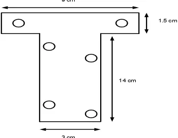
2.3 The Liaison between the Blade and Shaft
Liaison between the blades and shafts using an iron bar which is made in the shape of the letter "T". Liaison in this twist of the blade was obtained by a bit slope about 50. The purpose of this is to make the acquired-twisting lift and drag force that is good so that wind turbines can work well [3],[4],[11].
9 cm
1.5 cm
14 cm
3 cm
Figure 3. The Liaison between shaft and blade 0.0
2.0 4.0 6.0
1.9 2.1 2.3 2.5 2.7 2.9 3.1 3.3 3.5 3.7 3.9v (m/s)
PT(W)
harvesters. This is a used generator at wind turbines with a capacity of water-X-power 400 Watts. This Generator is considered according to the design of wind turbines to be made because it is a type of generator that is made for the purposes of small-scale wind turbine which has 6 poles excitation. Based on the technical specifications on the User Manual Wind turbine Air-X wind turbine is known that began spinning at wind speeds of 3.0 m/s. However, on horizontal Axis wind turbine designs are expected to be starting the turbine wind speeds can be lower than 3.0 m/s.
In general the voltage generated by the generator has the equation [12]:
e = B.l.v (6)
where,
e = Induction Voltage (V) B = magnetic field (Wb/m2) l = the long entanglement (m) v = rotation speed (rpm)
Usually the power equation for alternating voltage source is:
S = PL + jQ (7)
where,
S = apparent power = V.I (VA) (8)
PL = active power or load power = V.I.cos = I2R (Watt) (9)
Q = reactive power = V.I.sin = I2X (VAR) (10)
R =resistor (Ω)
X = reactance = XL - XC (Ω)
XL = inductive reactance = 2.π.f.L (Ω)
XC = capacitive reactance = 1/(2.π.f.C) (Ω)
f = frequency (Hz) L = inductance (Henry) C = capacitance (Farad)
From equation 2 and 9, then the efficiency of the HAWT prototype is:
% (11)
where.
= efficiency HAWT Prototype PL = load power (W)
PT = turbine mechanical power (W)
3. Eksperiment Results and Analysis
Prior to the field, the permanent magnet synchronous generator used to be tested in the laboratory. By providing the energy of motion coming from the motor, the generator will generate electrical energy. Figure 4a shows the circuit for testing permanent magnet generator. Figure 4b shows the resulting voltage permanent magnet generator for several rounds of the shaft. By providing the 300 rpm to 2500 rpm, generator produces a voltage from 2.1 Volts up to 21.1 volts.
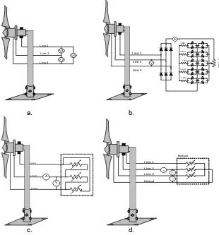
super bright white LED which consists of two groups of LED. Each group consists of ten LEDs. In the first group, LED construction are parallel which is a maximum of 5 kΩ resistance connected. While in the second group, every two LED is arranged parallelly and connected to a 1 kΩ, so the circuit will consist of the simillar five groups of LED. Before being connected to LED, alternating voltage must be rectified by diode rectifier.Finally, the experiment conducted with load in and Y connection. The circuit for testing can be depicted in Figure 5.
,
a. Circuit b. Result Voltage
Figure 4. Permanent Magnet Synchronous Generator Testing
V1
Figure 5. HAWT prototype experiment: a. No load circuit b. Circuit with LED load c. Circuit with
connection d. Circuit with Y connection 0
100 300 500 700 900
1100 1300 1500 1700 1900 2100 2300 2500
without load.
Figure 6. The curve of line voltage vs wind speed at no load condition
The graph shows that it looks that the greater the wind speed the greater resulting voltage generator will be. This is because the generator voltage is directly proportional to wind speed. Wind turbine begins rotating in the wind speed 1.9 m/s.
3.2 Eksperiment with LED
Figure 7 shows HAWT prototype that its blade are spinning. It is seen that LED is on.
a. The Prototype and circuit b. The result of LED Voltage
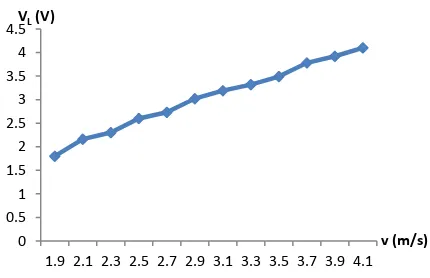
Figure 7. LED experiment in the Beach
Figure 7b shows that the resulting voltage rises linearly with an increase in wind speed. The resulting voltage of the generator is then rectified by the rectifier. The direct current from rectifier is used to light on the LEDs. LED started light on speed of wind at 2.3 m/s.
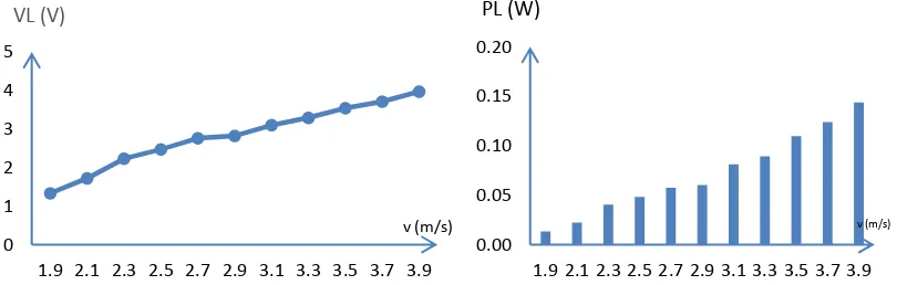
3.3 Eksperiment with Delta Connected Load
Figure 8a shows the voltage produced on the prototype delta relationship was HAWT with the load resistor 200 Ω. The resulting voltage generator will be even greater when the wind
0 0.5 1 1.5 2 2.5 3 3.5 4 4.5
1.9 2.1 2.3 2.5 2.7 2.9 3.1 3.3 3.5 3.7 3.9 4.1
v (m/s)
VL(V)
0 0.5 1 1.5 2 2.5 3 3.5 4 4.5
1.9 2.1 2.3 2.5 2.7 2.9 3.1 3.3 3.5 3.7 3.9 v (m/s)
speed that appears increasingly elevated, because the resulting voltage is proportional to the given rotational speed.
a. The voltage of Generator b. The Load power
Figure 8. HAWT Prototype with Connected Load Results
Figure 8b shows that load power is not equal to turbine power. Load power PL is
calculated from eq. (8), turbine power PT from eq. (2), efficiency from eq. (11). The decrease
of efficiency because there are losses at turbine such as drag force and at generator such as magnetic and copper losses. The average efficiency is obtained is 6.2%.
3.4 Eksperiment with Wye Connected Load
Figure 9a shows the curve of line voltage versus wind speed to 200 Ω.resistor load with wye connection. The curve shows that line voltage increase linearly to wind speed.
a. The voltage of Generator b. The power load
Figure 9. HAWT Prototype with Y Connected Load Results
Figure 9b shows the load power. Based on the load power, efficiency is calculated.The efficiency, then is obtained on the HAWT prototype Y connection was smaller than delta connection. The low efficiency of Y connection is caused by inductive reactance at the line. The average efficiency which resulted on this prototype is 3.7%.
Generally, small scale wind speed gives low efficiency of the prototype of wind turbine. This result is the same result as the study by [1] that little wind resource gives only 10% of the
using of speed-increase gearbox can increase generator rpm even though the gearbox can contribute to vibration [14]. The hybrid between horizontal and vertical axis can increase the efficiency due to vertical axis wind turbine can rotate at smaller scale speed rather than the horizontal axis [15]. Finally, for the generator point of view, Refs. [16] and [17] can increse the performance of the prototype.
4. Conclusion
The simple HAWT prototype has already been made. This prototype has three blades. Design of blade is flat plate section. By using resistor 200 Ω, average efficiency to delta connection is 6.2% and wye connection is 3.7%. Actually, the efficiency of both are still small. There are many losses in this prototype. Those are losses at turbine, generator and at line.
Acknowledgment
This work was supported by DGHE (Dikti-Decentralisation Research) Project No. 15/UN.16/PL-HB/2013 and Engineering Faculty DIPA, University of Andalas, Indonesia under Project No. 035/PL/SPK/PNP/FT-Unand/2013.
References
[1] Daut I, Irwanto M, Suwarno, Irwan Y.M, Gomesh N, Ahmad N.S. Potential of Wind Speed for Wind
Power Generation in Perlis, Northern Malaysia. TELKOMNIKA. 2011; 9(3): 575-582.
[2] Latif M. Savonius Turbine Prototype Efficiency at Small Scale Wind Speed. Jurnal Rekayasa
Elektrika. 2013; 10(3): 147-152.
[3] Patel M.R. Wind and Solar Power Systems. CRC Press. New York. 1999.
[4] Hau E. Wind Turbines Fundamentals, Technologies, Application, Economics. Springer: 2nd Edition.
2005.
[5] Zheng Y, Zhao R, Liu H. Dynamic Response of Flexible Wind Turbine Blade. TELKOMNIKA, 2013;
11(12): 7052-7057.
[6] Cui-ping L, Jochema E, Zhang Y, Farida N.R. Wind power development and policies in China.
Renewable Energy. 2010; 35(9): 1879–1886
[7] Xiao-ping R, Chang-qing C, Jian W, Zhi-chao X. Aplications of Metrological Measurement in Wind
Power Generation. TELKOMNIKA. 2012; 10(6): 1249-1253.
[8] Islam M.R, Mekhlief S, Saidur R. Progress and Recent Trends of Wind Energy Technology,
Renewable Energy and Sustainable Energy Reviews. May 2013; 21: 456-468.
[9] Musyafa A, Negara IMY, Robandi I. A Wind Turbine For Low Rated Wind Speed Region In East
Java. International Journal Of Academic Research. September 2011; 3(5).
[10] Mishanaevsky L.Jr., Freere P, Sinha R, Acharya P, Shrestha R, Manandhar P. Small Wind Turbines with Timber Blades for Developing Countries: materials choice, development, installation and
experiences. Renewable Energy. 2011; 36: 2128-2138.
[11] Schubel P.J, Crossley R.J. Wind Turbine Blade Design. Energies. 2012; 5: 3425-3449.
[12] Wildi T. Electrical Machines, Drives, and Power Systems. Prentice Hall, Fourth Edition. 2000
[13] Luna M, Pucci M, Vitale G. Design of a Simple, Effective and Low Cost Micro-Wind Energy
Conversion System. The Open Renewable Energy Journal. 2011; 4(Suppl 1-M6): 34-41.
[14] Yafeng L, Yuxiu X. Operational Modal Analysis of wind Turbine speed-increase Gearbox.
TELKOMNIKA. November 2013; 11(11): 6699-6705.
[15] Velan SSS, Muthukumaran G, Balasubramaniyan S. Windmill Power Generation Using
Mult-Generator and Single Rotor (Horizontal and Vertical Blade). Journal of Energy Technologies and
Policy. ISSN 2225-0573 (Online), 2012; 2(4).
[16] Prakashkumar V. A Control Strategy for a Variable-Speed Wind Turbine with a Permanent-Magnet
Synchronous Generator. IJART (International Journal of Advance Research in Technology). 2012;
2(3): 5-10.
[17] Sun X, Cheng M, Hua W, Xu L. Optimal Design of Double-Layer Permanent Magnet Dual
Mechanical Port Machine for Wind Power Application. IEEE Transactions on Magnetics. October