DOI: 10.12928/TELKOMNIKA.v14i3A.4425 187
Special Device Conveying Coal in the Freight Yard of
the Train-Design of the Driving Roller of the Belt
Conveyor
Qiulei Du*1, Wusheng Tang2, Liai Pan3
1Special Education College of Changchun University, Changchun City, Changchun, Jilin, 130022, P. R.
China
2Scientific Research Administrative Dept of Changchun University, Changchun City, Changchun, Jilin,
130022, P. R. China
3Mechanics Engineer College of Changchun University, Changchun City, Changchun, Jilin, 130022, P. R.
China
*Corresponding author, e-mail: [email protected]
Abstract
Based on the survey of existing belt conveyor, it has been mainly studied to the design of driving roller parts for the stationary belt conveyor in the freight yard of the train. In this paper, the structure of roller has been analyzed and designed. The thickness of the roller, the strength of cylinder and etc have been calculated and checked to meet the requirements of the freight yard coal and further improve the performance of the belt conveyor.
Keywords: Belt conveyor, Driving roller, Device conveying coal
Copyright © 2016 Universitas Ahmad Dahlan. All rights reserved.
1. Introduction
Belt conveyor is one of the most main material conveying equipments, mainly composed of the following parts: the first frame, driving device, driving roller, frame, roller, the middle frame, redirection device of tail, discharging device, cleaning device, safety device, etc. The driving roller is a major part of the belt conveyor transmission power, there are two major roles: one is the transmission power, and the second is to change the running direction of the conveyor belt. In a single point driving system, it can be divided into single roller drive and double roller drive. The single roller drive is used to the conveyor of small power; the double roller drive is used to the conveyor of larger power. The characters are not only compact structure, but also can increase the circumference angle in order to increase traction of the transmission roller.
The motor drive can be respectively used drive double roller and can make the roller with speed operation by the gear. The design quality of belt conveyor roller is related to the performance of the entire conveyor system, safety and reliability [1].
2. Selection and Design of the Driving Roller
The driving roller is a major part of the transmission power; it is part to running conveyor belt relying on the friction between the conveyor belts. According to the bearing capacity, the driving roller can be divided into light, medium, and heavy. There are several different diameters of axle and the center span for selection to the same kind of roller [2].
(1) Light: The aperture of bearing is 80-100mm. The connecting structure of shaft and wheel hub is welded tube of single bond and single plate. It is one-way out of the shaft.
(2) Medium: The aperture of bearing is 120-180mm. The shaft and wheel hub are connected by expansion sleeve.
The driving roller structure of the belt conveyor is steel plate welding structure, the structure of cast steel or cast iron. The surface form of the driving roller is steel casting smooth roller, rubber roller, etc. The main drawback of the steel smooth roller is that the surface friction coefficient is small, generally used in ambient humidity small short distance on the conveyor. The main advantage of the rubber casting roller is that the surface friction coefficient is big, applicable to the big environmental humidity and long distance belt conveyor. The rubber casting roller can be divided into smooth rubber casting roller, herringbone groove casts glue roller, the diamond and glue roller by its surface shape.
To increase the coefficient of friction, the steel smooth drum surface of the herringbone grooved roller of rubber casting is added to a layer of rubber layer with herringbone groove. The roller is directivity, may not reverse operation. The groove of the herringbone grooved drum of rubber casting can interrupt the thin film of water, and no water. When the conveyor belt and roller contact at the same time, the surface of the conveyor belt can be squeezed into the groove. For these two reasons, even in damp places work, the friction coefficient what is reduced is small. Considering the actual situation of the design and working environment of conveyor: used for factory production, environment humidity, big power consumption, easy to slip, so we choose this drum. The surface of the cast rubber is thick and wearing resistance, good quality; and plastic bags rubber off easily, screw head is easy to be show and scratches belt, service life is shorter. Comparing the two rubbers, the casting roller has been selected.
3. Design Calculation of the Driving Roller [3]
3.1. The Determination of Power P3, Rotate Speed N3 and Torque T3 of the Shaft 3
3
250 0.97 kw
228.2kw
p
(1)
1000
63.3r/min
12.6
m w
n
n
i
(2)
So, angular speed of the shaft
w
n 2
63.3 2
6.63rad / s
60
60
,
r
6.63 0.315=2.08m/s
,1
6.63
f=
1.06s
2
2
3.2. Determination of the Minimum Diameter of the Shaft
3 0
d A p
n
(3)
In the formula, p is transmission power of the shaft, kW; n is speed of the shaft, r/min. Selecting the material of shaft was 45 steel, quenched and tempered treatments. Selecting A0=112. So,
3 3
0
p 228.2
d A 112 171.7
n 63.3 mm
3.3. Calculation of Thickness of the Roller Body
Q235A steel plate has been used for electric the roller material, and taking [ ] 4
s
. To
Q235A steel, s 235N mm/ 2, so
2
2 2 2
86.71 p 0.0338 0.1875 ( )
t l D mm
R
(4)
In the formula, p is power, kW; v is belt speed, m/s; l is length of the roller, mm; R=D/2,
mm;
[ ]
is allowable stress, N/mm2.Table 1. The corresponding table of width and length of DTII Belt conveyor Width/belt 800 1000 1200 1400
Length of the
electric roller 950 1150 1400 1600
In the table 1, the length of the roller l=1600mm has been illustrated.
2 2
2
2 2
2
86.71
0.0338
0.1875
(
)
228.2
86.7
0.0338 1600
0.1875 630
40
2 315
p
t
l
D mm
R
mm
3.4. Checking Cylinder Strength of the Electric Roller [4]
228.2
1000 1000 114100 2 u P F N (5) 1
1
Ue
F
F
e
(6)In the formula, Fu is driving force of the circumference, N; is the friction coefficient between conveyor belt and roller, according to the humid air operation, =0.2; is chamfer of the roller, taking in commonly between .8~ . rad ~ values, . rad .
Thus it was concluded that: e . . .
2
1
UF
F
F
(7)
In the formula, F1 is pull of the tension side, N; F2 is pull of the loose side, N. Plug in to
1 2 U 224200 , 2 U 114100
F F N F F N,
The approximate formula of the average tension F.
1 2
0
2
1.05 1.575 179707.5
2 2
U U
U
F F
F F
F K F N
3
630
114100 35941.5
2 3
U D
M F N m
(8)
In the formula, M3 is torque of the roller.
max
1 179707.5 1.6
35941.5
2 4 8
F
M N m
For 2 2 3 3 ( / ) ( / ) 2 n M N mm W M M N mm W W
(9)In the formula, W is bending section modulus. For electric roller of inner diameter d and outer diameter D, the bending section modulus should be selected according to cylindrical shell theory:
2 3
0.1963 ( ) 16
W Rt R R t mm
So
2 2 5.093 2 ( / )
0.1963
M M M
N mm
W R t R t
(10)
2
3 3 3
2 2.547 2 ( / )
2 2(0.1963 )
M M M
N mm
W R t R t
(11)
In the formula, R is the average radius of the roller; t is the thickness of the roller. So the normal stress,
2
2 2
35941.5
5.093 5.093 46.1 /
315 40 M N mm R t , 2 3 2 2 35941.5
2.547 2.574 23.3 /
315 40 M N mm R t
According to the fourth strength theory, composite bending moment can be written as:
(12)
In the formula, is the normal stress under the action of bending, N/mm2; is the shear stress under the action of torque N/mm2; [] is allowable stress, according to the fourth strength
theory, taking s [ ]= 1.5 N/mm2.
Usually the electric roller is made in steel, z=235Mpa, and the allowable stress was
[]=156.7Mpa.
2 2 2 2 2
3 46.1 3 23.3 61.27(N/mm )<[ ] h
Calculate intensity met the
requirements.
4. Results and Analysis
4.1. Structural Design of the Driving Roller Shaft [7]
Figure 1. Assembly scheme and stress figure of the driving roller shaft
[image:5.595.188.404.314.404.2](2) According to the requirement of the location and assembly, the diameter and length of paragraphs of shaft has been determined. The shaft on the left side has been shown in figure 2.
Figure 2. The shaft on the left side.
(3) The axial positioning of shaft parts.
Coupling and shaft parts have been adapted to flat key link. The rolling bearing and shaft radial location have been adapted transition fit to ensure. Size tolerance of the diameter of the shaft was m6.
(4) Determination of sizes of the shaft rounded corners and chamfer.
Chamfering of the shaft end has been took 2 45 °, the radius of the shoulder wasR2. (5) Load on the shaft
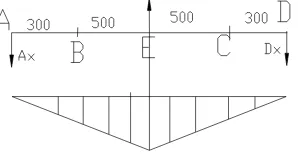
The stress of the shaft in the horizontal direction has been shown in figure 3.
Figure 3. The moment diagram of shaft in the horizontal direction
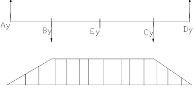
[image:5.595.222.371.562.639.2]Figure 4. The moment diagram of shaft in the vertical direction
For
M A
( )
0
, so Ay Dy 4341.4N, ME MBMC 1302.42N m .Torque diagram of the shaft has been shown in figure 5.
Figure 5. Torque diagram of the shaft
From structure diagram and bending moment and torque of the shaft, the section E was a dangerous section of shaft.
2 2
0 71894.8
E E H
M M M N m
4.2. Checking the Strength of the Shaft According to Synthetic Stress of the Bending and Torque
During checking, strength of the dangerous section E under maximum bending moment and torque of the shaft usually only has been checked [5, 6].
According to.
2 2
( )
ca
M T
W
(13)
In the formula,
ca is calculated stress of the shaft, MPa; M is bending moment of theshaft, Nm; T is torque of the shaft Nm; W is section coefficient of the shaft bending, mm3, for no
keyway, by the type
3 3
3.14
0.1 32
d
W d
; [
1] is permissible bending stress, and the selectedmaterial was 45 steel, quenched and tempered treatment,[1]60MPa.
2 2 2 2
3
( ) 71894.8 (0.6 34428.63)
47.9 0.1 250
ca
M T
MPa W
For,
ca
[
1]
,so the shaft was safety.5. Conclusion
design [8, 9]. From what has been discussed above, the conclusions that selection analysis and design calculation can make the freight yard coal required further improvement of the performance of the belt conveyor.
References
[1] Du QL. Coal Handling Plant Design for Train Yard. Open Journal of Mechanical Engineering. 2015; 3(1): 38-40.
[2] Hamilton TW, Melbourne WG. Information content of a signle pass of Doppler data from a distant spacecraft. JPL Space Programs Summary. 2003; 37-39(3): 18-23.
[3] Yang YH, Huang HZ, Shen QN, Wu ZH, Zhang Y. Research on Intrusion Detection Based on Incremental GHSOM. Chinese Journal of Computers. 2014; 37(5): 1216-1224.
[4] Du QL, Jin L. Research and Exploration of Sheet Material Bending Machine. Journal of Chemical and Pharmaceutical Research. 2014; 6(1): 355-362.
[5] A. Triwiyatno. Engine Torque Control of Spark Ignition Engine using Fuzzy Gain Scheduling.
TELKOMNIKA Indonesian Journal of Electrical Engineering. 2012; 10(1): 83-90.
[6] Tiezhu Q, Xiaolu L, Xueying Z. Singularity Detection of Magnetic Memory Signal of Steel-Cord Conveyor Belt. TELKOMNIKA Indonesian Journal of Electrical Engineering. 2013; 11(9): 4904-4910. [7] Xu Z. Computational Method on the Shearer Position. TELKOMNIKA Indonesian Journal of Electrical
Engineering. 2013; 11(9): 4990-4996.
[8] Ali MM. Factors effect on the effective length in a double strap joint between steel plates and CFRP.
International Journal of Advances in Applied Sciences. 2012; 1(1): 11-18.