ISSN: 1693-6930
accredited by DGHE (DIKTI), Decree No: 51/Dikti/Kep/2010 497
Improving Output Voltage of the Three Phase
Six-Switch Inverters
Ebrahim Babaei*1, Mehdi Mahaei2 1
Faculty of Electrical and Computer Engineering, University of Tabriz, Tabriz, Iran 2Department of Electrical Engineering, Ahar Branch, Islamic Azad University, Ahar, Iran
Ph./Fax: +989143075824/+984115261624 [email protected], [email protected]
Abstrak
Pada makalah ini diusulkan sebuah method sederhana untuk memilih sudut konduktif terbaik berdasarkan faktor daya beban pada inverter enam-saklar tiga fase. Sudut konduktif dari 120º sampai 180º, dan faktor daya dari 0 ke 1 diubah untuk variasi beban mendahului dan tertinggal. Untuk selanjutnya nilai-nilai RMS dan THD tegangan keluarannya dipelajari. Hasil simulasi menunjukkan bahwa sudut konduktif khusus untuk masing-masing faktor daya spesifik harus digunakan untuk meningkatkan indeks modulasi. Penerapan sudut konduktif konvensional 120º, 180º dan 150º pada beberapa faktor daya meningkatkan THD dan menurunkan tegangan RMS keluaran.
Kata kunci: faktor daya, inverter, sudut konduktif, THD
Abstract
In this paper, a simple method for selecting the best conductive angle based on power factor of load in three phase six-switch inverters is proposed. Conductive angle from 120º to 180º, and power factor from 0 to 1 are changed for lead and lag loads. Then RMS and THD values of the output voltage are studied. Simulation results show that a special conductive angle for each specific power factor has to be used to improve the mentioned indices and applying conventional conductive angles 120º, 180º and 150º in some power factors increases THD and decreases RMS of output voltage.
Keywords: conductive angle, inverter, power factor, THD
1. Introduction
Three phase six-switch inverters are used in many industries [1]-[6]. For this reason, many researches have been presented recently investigating different types of fault that commonly occur in these inverters. Of these, the improvement of the output waveform and reduce harmonic distortion is very important [7]. Therefore, using electronic devices, various types of inverters are presented with different structures, which can reduction harmonic and can lead to improve the output voltage too.
Although, this inverters increase he quality of output voltage and current, but lead to other disadvantages, including increased size, weight and price. Therefore, three phase six-switch inverters are important, still [8], but these inverters have been used in particular conductive angles such as 120°, 180° and 150° in pu blished papers [7]-[9].
In this paper, a new method for selecting conductive angle based on the power factor of load and needed aim is presented. The conductive angle can vary from 120° to 180° according to these parameters. Needed aims can be low THD and high RMS of output voltage. So conductive angle is changed from 120° to 180° for d ifferent power factor of lead and lag loads with simulation. The results show that each conductive angle can be selected in 120-180 rang, in terms of power factor and needed aim.
2. Structure of three-phase inverters
voltage, but producing two same dc voltage sources is a disadvantage that will create a problem in the industry generally.
Figure 1. Three-phase inverter
3. 180-degree conduction
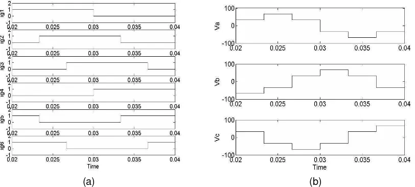
This conductive angle is used in many industries. It results in six modes for each period, considering the number of transistors, which each of them is on for a half a period.T1, T5 and T6 transistors turn on in first half time and other transistors are off. AC voltage is produce, by repeating the same process in the next modes. Figure. 2 shows pulses and output voltage for an ohmic load.
(a) (b)
Figure 2. Pulses and Output voltage in 180-degree conduction; (a) Pulses of 180-degree conduction; (b) Output voltage in 180-degree conduction
Analysis of Fourier series of the VA Waveform is as followed [5]:
t n n n a
o
n
d
V
V
π π sin ω6 cos 3 4 180
, ,
,... 3 , 1
⋅ =
∑
∞=
o (1)
V
4. 120-degree conduction
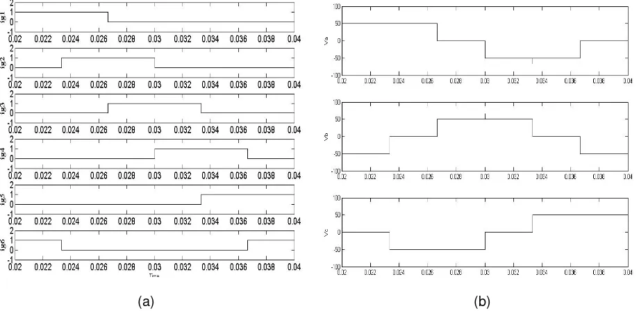
In this type of conduction, each of transistors turns on for 1/3 period. Pulses and output voltage for an ohmic load are shown in Figure. 3.
(a) (b)
Figure 3. Pulses and Output voltage in 120-degree conduction; (a) Pulses of 120-degree conduction; (b) Output voltage in 120-degree conduction
Analysis of output voltage to Fourier series is extracted from the following equations [5].
)
RMS and THD values of output voltage are equal to:
V
5. 150-degree conduction
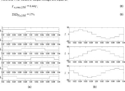
In this type of conduction, each of transistors turns on for 5/12 period. Pulses and output voltage for an ohmic load are shown in Figure. 4.
Fourier series of the output voltage is calculated as follows [5]:
RMS and THD values of output voltage are equal to:
V
Vo,rms,150o=0.44 i (8)
% 17 150
, =
THDVo o (9)
(a) (b)
Figure 4. Pulses and Output voltage in 150-degree conduction; (a) Pulses of 150-degree conduction; (b) Output voltage in 150-degree conduction
6. Changing the power factor and conductive angle
THD of the output voltage is affected by the power factor and the conductive angle usually. Power factor of load can not be determined by the designers, and conductive is a facility for designer. So the suitable conductive angle is selected considering high RMS and low THD of the output voltage.
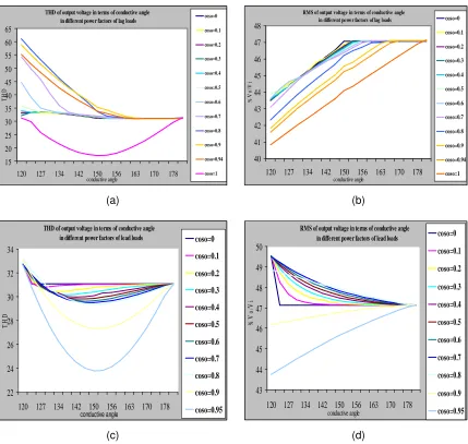
Conductive angle is changed from 120° to 180° for d ifferent power factors of lead and lag loads with simulation then RMS and THD of the output voltage are measured. Results of the simulation for the different power factors and 120-180 degree conductions are shown in Figure. 6.
The results of simulation can be expressed as follows:
• The RMS of the output voltage increases by increasing the conductive angle in lead loads.
• The RMS of the output voltage increases by increasing the conductive angle in lag loads (power factor 0.9 and more than 0.9), that value of this increasing, decreases by increasing capacitive characteristics.
• The RMS of the output voltage decreases by increasing the conductive angle in lag loads (power factor less than 0.9). But increasing conductive angle from a special point, in low power factors, have a little effect on the output voltage.
• The THD of the output voltage in terms of conductive angle is constant in inductive loads.
• The THD of the output voltage decreases by increasing conductive angle from 120-150 degree in ohmic loads, and it increases with increasing conductive angle from 150-180 degree.
• The THD of the output voltage decreases by increasing conductive angle from 120-150 degree in lead loads, and it is constant with increasing conductive angle from 150-180 degree.
• The THD of the output voltage decreases by increasing conductive angle from 120-150 degree in lag loads, and it increases with increasing conductive angle from 150-180 degree.
(a) (b)
(c) (d)
Figure. 6. THD and RMS of output voltage in terms of power factor and conductive angle for lead and lag loads; (a) THD of the output voltage for a lag load; (b) RMS of the output voltage for a lag load; (c) THD of the output voltage for a lead load; (d) RMS of the output voltage for a lead load
7. Conclusion
THD and RMS of the output voltage can be affected with power factor and conductive angles in three phase six-switch inverters. Conductive angle can be changed by designer. So, needed aim can be found with selecting suitable conductive angles. The results of the Elimination Capability. IECON. N. Carolina, USA. 2005: 1695-1700.
THD of output voltage in terms of conductive angle in different power factors of lag loads
15
120 127 134 142 150 156 163 170 178
conductive angle
RMS of output voltage in terms of conductive angle in different power factors of lag loads
40
120 127 134 142 150 156 163 170 178 conductive angle
THD of output voltage in terms of conductive angle in different power factors of lead loads
22
120 127 134 142 150 156 163 170 178 conductive angle
RMS of output voltage in terms of conductive angle in different power factors of lead loads
43
[2] Zenginobuz G, Cadirici I, Ermis M, Barlak C. Performance Optimization of Induction Motor During Voltage Controlled Soft Starting. IEEE Trans. Energy Convers. 2004; 19(2): 278-288.
[3] Lai YS, Wang WK, Chen YC. Novel Switching Technique for Reducing the Speed Ripple of ac Drives with Direct Torque Control. IEEE Trans. Ind. Electron. 2004; 51(4): 768-775.
[4] Jidin A, Sutikno T. Matlab/Simulink Based Analysis of Voltage Source Inverter with Space Vector Modulation. TELKOMNIKA Indonesian Journal of Electrical Engineering. 2009; 7(1): 23-30.
[5] Sujanarko B, Ashari M, Purnomo MH. Improved Voltage of Cascaded Inverters Using Sine Quantization Progression. TELKOMNIKA Indonesian Journal of Electrical Engineering. 2010; 8(2): 123-130.
[6] Tumbelaka HH, Borle LJ. Harmonic Mitigation Using a Polarized Ramp-time Current-Controlled Inverter. TELKOMNIKA Indonesian Journal of Electrical Engineering. 2010; 8(3): 235-244.
[7] Iqbal A, Moinuddin S. Assessment of Torque Pulsation in Inverter Fed Three-Phase Induction Motor Drive for 180° and 150° Conduction Modes. International Conference on Information and Communication Technology in Electrical Sciences (ICTES). 2007: 323-328.
[8] Saied MH, Mostafa MZ, Abdel-Moneim TM, Youse HA. On Three-Phase Six-Switch Voltage Source Inverters: A 150° Conduction Code. IEEE International Symposium on Industrial Electronics. 2006; 2: 1504-1509.