I
EFFECT OF TERRAIN FEATURES ON WAVE PROPAGATION
NURASLINDA BINTI ADNAN
This Report Is Submitted In Partial Fulfilment Of Requirement For The Bachelor Degree of for Electronic Engineering (Wireless Communication)
Faculty of Electronic and Computer Engineering Universiti Teknikal Malaysia Melaka
II
Tajuk Projek : Effect of Terrain Features on Wave Propagation
Sesi Pengajian : SESI 2012/2013
Saya NURASLINDA BINTI ADNAN mengaku membenarkan Laporan Projek Sarjana Muda ini disimpan di Perpustakaan dengan syarat-syarat kegunaan seperti berikut:
1. Laporan adalah hakmilik Universiti Teknikal Malaysia Melaka.
2. Perpustakaan dibenarkan membuat salinan untuk tujuan pengajian sahaja.
3. Perpustakaan dibenarkan membuat salinan laporan ini sebagai bahan pertukaran antara institusi pengajian tinggi.
4. Sila tandakan ( √ ) :
SULIT*
*(Mengandungi maklumat yang berdarjah keselamatan atau kepentingan Malaysia seperti yang termaktub di dalam AKTA RAHSIA RASMI 1972)
TERHAD** **(Mengandungi maklumat terhad yang telah ditentukan oleh
III
“I hereby declare that this is the results of my own paper except for quotes as cited in the references.”
Signature :
Author : Nuraslinda Binti Adnan
IV
“I hereby declare that I have read this report and in my opinion this report is sufficient in terms of the scope and quality for the award of Bachelor Degree of
Electronic and Computer Engineering (Wireless Communication) with Honours.”
Signature :
Supervisor’s Name : Puan Mawarni Binti Mohamed Yunus
V
This project and research work is dedicated to my beloved parents for their devoted
caring throughout my life, my loving sister, also my friends for their encouragement
VI
ACKNOWLEDGEMENT
All admires to Almighty ALLAH, the most gracious and the most merciful,
who bequeathed I with wellbeing and abilities to complete this project successfully.
I wish to express my deep gratitude to my project supervisor, Pn. Mawarni
Binti Mohamed Yunus for her continuous heart and soul support to complete the
project in the best possible way. She is always a source of inspiration and motivation
for me. Her encouragement and support never faltered.
I are also very thankful to my entire fellow colleague’s who have helped me
mentally as well as academically, in every hour of necessitate.
Finally, I am wildly grateful to my parents for their everlasting moral support
and encouragements. It is to them I dedicated this project.
Nuraslinda Binti Adnan
VII
ABSTRACT
Path-loss prediction algorithms for advanced wireless communication system
planning have long considered the effect of electromagnetic propagation over
buildings between the base station and subscriber. It briefly discusses the theory of
reflection, diffraction and scattering over urban, suburban and rural area. This
research is to present the implementation of different models for predicting the path
loss between a base station antenna and mobile station antennas. The prediction of
path loss is a very important step in planning a mobile radio system and accurate
prediction methods are needed to determine the parameters of a radio system which
will provide efficient and reliable coverage of a specified service area. The
significant of this research is to determined the best emperical method for predicting
the path loss between base station antenna and mobile station. This research
describes three chosen path loss models which is Hatta-Okumura model, Stanford
University Interim (SUI) model and Ericson model. In this research, the analyzing
model above in different distance range, height of base station and height of mobile
station in urban, suburban and rural environment. As a conclusion, in order to build
an effective communication link the precise path loss prediction is very important.
For each type of terrains (urban, suburban and rural) Hatta-Okumura model are the
best path loss prediction model.
VIII
ABSTRAK
Path loss prediction adalah penting dalam perancangan sistem komunikasi
yang maju. Ia adalah kesan daripada penyebaran electromagnetik diantara bangunan
daripada stesen pemancar kepada stesen penerima. Secara ringkasnya, kajian ini
membincangkan kesan aktiviti pantulan, pembiasan dan penyebaran di kawasan
Bandar, pinggir Bandar dan luar Bandar. Kajian ini membincangkan kepelbagaian
model path loss prediction untuk meramalkan path loss yang terjadi apabila isyarat
di hantar daripada stesen pemancar kepada stesen penerima. Ini adalah satu langkah
yang amat penting dalam perancangan system komunikasi yang berkesan di setiap
kawasan. Kajian ini menerangkan tiga kaedah erbaik untuk path loss prediction yang
mana ia nya adalah kaedah Hatta-Okumura, kaedah Stanford university Interim
(SUI) dan kaedah Ericson. Saya juga menganalisis kaedah tersebut dalam jarak
kawasan liputan yang berbeza, ketinggian stesen pemancar yang berbeza dan
ketinggian stesen penerima yang berbeza di kawasan Bandar, pinggir Bandar dan
luar Bandar. Kesimpulannya, untuk membina satu sistem komunikasi yang baik, path
loss perlu diramal secara tepat. Melalui kajian ini dapat saya nyatakan untuk setiap
jenis kawasan (Bandar, pinggir Bandar dan luar Bandar) model Hatta-Okumura
IX
X
4 Result and Discussion 20
4.1 The Simulation Result 20
4.2 Tabulate Data 40
4.3 Analysis of Simulation Result 41
5 Conclusion 48
6 Referrences 49
7 Appendices 52
Appendix 1: Coding for Urban Area 52
Appendix 2: Coding for Suburban Area 53
XI
List of Tables
No. Title Page
1 Table 3.1: Correction factor for Hatta-Okumura model 23
2 Table 3.2: Correction factor for SUI model 24
3 Table 3.3: Correction factor for Ericson model 25
4 Table 4.1: Summarized of path loss data in urban area 40
5 Table 4.2: Summarized the path loss value in suburban area 40
XII
List of Figure
No. Title Page
1. Figure 2.1: Earth layer 6
2. Figure 2.2: Reflection and refraction 7
3. Figure 2.3: The angle of reflection = the angle of incidence 8
4. Figure 2.4: Wave refraction 8
5. Figure 2.5: Diffraction Illustration 8
6. Figure 2.6: Diffraction 9
7. Figure 2.7: The Diffraction Phenomenon 9
8. Figure 2.8: Different diffraction effects 10
9. Figure 2.9: Scattering effect 11
10. Figure 2.10: Urban Area 13
11. Figure 2.11: Suburban Area 15
12. Figure 2.12: Rural Area 16
13. Figure 2.13: Categories of Propagation model 18
14. Figure 3.1: Project methodology flow chart 19
15. Figure 4.1: Path loss in urban area for distance up to 5km 27
16. Figure 4.2: Path loss in urban area for distance up to 50km 27
17. Figure 4.3: Path loss in suburban area for distance up to 5km 28
18. Figure 4.4: Path loss in suburban area for distance up to 50km 28
19. Figure 4.5: Path loss in rural area for distance up to 5km 29
20. Figure 4.6: Path loss in rural are for distance up to 50km 29
21. Figure 4.7: Path loss in urban area for distance up to 5km 30
22. Figure 4.8: Path loss in urban area for distance up to 50km 30
23. Figure 4.9: Path loss in suburban area for distance up to 5km 31
24. Figure 4.10: Path loss in suburban area for distance up to 50km 31
25. Figure 4.11: Path loss in rural area for distance up to 5km 32
26. Figure 4.12: Path loss in rural area for distance up to 50km 32
27. Figure 4.13: Path loss in urban area for distance up to 5km 33
28. Figure 4.14: Path loss in urban area for distance up to 50km 34
29. Figure 4.15: Path loss in suburban area for distance up to 5km 34
30. Figure 4.16: Path loss in suburban area for distance up to 50km 35
XIII
33. Figure 4.19: Path loss in urban area for distance up to 5km 36
34. Figure 4.20: Path loss in urban area for distance up to 50km 37
35. Figure 4.21: Path loss in suburban area for distance up to 5km 37
36. Figure 4.22: Path loss in suburban area for distance up to 50km 38
37. Figure 4.23: Path loss in rural area for distance up to 5km 38
38. Figure 4.24: Path loss in rural area for distance up to 50km 39
39. Figure 4.25: Analysis of simulation results for urban
environment in different receiver antenna (Rx) height,
distance up to 5km and transmit antenna (Tx) is 30m. 42
40. Figure 4.26: Analysis of simulation results for urban
environment in different receiver antenna height,
distance up to 5km and transmit antenna is 80m. 42
41. Figure 4.27: Analysis of simulation results for urban
environment in different receiver antenna height,
distance up to 50km and transmit antenna is 30m. 43
42. Figure 4.28: Analysis of simulation results for urban
environment in different receiver antenna height,
distance up to 50km and transmit antenna is 80m. 43
43. Figure 4.29: Analysis of simulation results for suburban
environment in different receiver antenna height,
distance up to 5km and transmit antenna is 30m. 44
44. Figure 4.30: Analysis of simulation results for suburban
environment in different receiver antenna height,
distance up to 5km and transmit antenna is 80m. 44
45. Figure 4.31: Analysis of simulation results for suburban
environment in different receiver antenna height,
distance up to 50km and transmit antenna is 30m. 45
46. Figure 4.32: Analysis of simulation results for suburban
environment in different receiver antenna height,
distance up to 50km and transmit antenna is 80m. 45
47. Figure 4.33: Analysis of simulation results for rural
environment in different receiver antenna height,
distance up to 5km and transmit antenna is 30m. 46
48. Figure 4.34: Analysis of simulation results for rural
environment in different receiver antenna height,
distance up to 5km and transmit antenna is 80m. 46
49. Figure 4.35: Analysis of simulation results for rural
environment in different receiver antenna height,
distance up to 50km and transmit antenna is 30m. 47
50. Figure 4.36: Analysis of simulation results for rural
environment in different receiver antenna height,
1
CHAPTER 1
INTRODUCTION
According to the technological advancements which permit wider
deployment nowadays, wireless communication has been grow rapidly in mobile
communications field [1,2]. The requirement for high quality and high capacity
networks, estimating coverage accurately has become extremely important.
Therefore, for more accurate design coverage of modern networks, signal strength
measurements must be taken into account in order to provide an efficient and reliable
coverage area [3].
This research is to discuss the impact of terrains future on wave propagation.
The common type of terrains future on wave propagation field is urban environment,
rural place, forest environment and suburban area. Furthermore, the effect of hills,
vegetation effects, high land, high buildings, vehicles and other obstacles will
contribute to the great path losses in mobile communication.
Any of the ways in which wave are travel are called wave propagation. Radio
wave propagation is propagation of radio frequency electromagnetic waves in the
2
radio waves propagate depends on certain factors such as the wavelength and how far
the waves are transmitted. Not like the wired channels that are stationary and
predictable, radio channels are extremely random and do not easily analyze.
Over the years, a lot of study had been done about how the types of terrain
give an effect on wave propagation. Cities are frequently built on rolling hills or on
undulating terrain so that, radio propagation may be simultaneously affected by both
buildings and terrain [4]. That has long been recognized that communication by
means of radio waves in forest environments is affected by transmission losses which
are substantially higher than those occurring in the absence of vegetation [5]. All this
studies are briefly explain the effect of terrains features on wave propagation [6-18].
The objectives of this research are to estimates the effect of natural terrain
features on the wave propagation. Natural terrain is referring to the location of the
base station (transmitter). Either in urban area or suburban area or rural places, all
this location will contribute to interferences of wave propagation. Based on the study
from previous paper, the main effect from each area could determine such as
reflection, diffraction and scattering. The explanation about each effect will discuss
in next chapter.
Besides that, this research is to implement the chosen models for predicting
the path loss between the base station (transmitter) and mobile station (receiver).
From the study, the path loss prediction on wave propagation could be determined by
so many technique such as the slab model of the forest [5], 3D Parabolic equation
[18] and others techniques. The model of predicting the path loss will discuss
detailed in next chapter.
The main issue of this research is investigation the factor of natural terrains
on wave propagation. When wave are propagate in urban area, there will have tall
tower, huge building, vehicles, diffraction over roof top and other obstructions.
While, on suburban area there has vegetation effect and buildings reflection. Then,
for rural place maybe there has high land, hills and foliage effect that has to be
considered in field to predict the path loss. All this three types of terrains has their
correction environment factor that determine in each path loss prediction model.
Moreover, the height of base station antenna and mobile station antenna also give
effect on wave propagation loss [19].
This research is limited on certain range of distance, height base station and
3
the cellular frequency of 2.4 GHz. There are several empirical propagation models
which can precisely calculate up to 2 GHz. In recent study, has determined the path
loss prediction for WiMAX application [20-22].
This research deals with how the natural terrains give effect on wave
propagation. First of all, the basic mechanism of wave propagation had been
discussed in detail. Next, the three chosen model for path loss prediction which is
Hatta-Okumura model, SUI model and Ericson model had been described briefly
with varies base station antenna height and mobile station antenna height which have
been proposed for frequency at 2.4GHz in urban and suburban and rural
environments. Otherwise, this research also provides the development of MATLAB
coding and run that simulation program for predicting path loss.
In short, this research starts with the phenomenon of the natural terrains on
wave propagation. Then, understand the theory of wave propagation mechanism in
term of path loss prediction. Next, familiar with MATLAB program and build the
coding. In chapter 2, it discusses the theoretical background study of this research
and in chapter3, discusses the path loss model prediction. Chapter 4 is about
4
CHAPTER 2
LITERITURE REVIEW
Over the years, a lot of study had been done about how the types of terrain
give an effect on wave propagation. Cities are frequently built on rolling hills or on
undulating terrain so that, radio propagation may be simultaneously affected by both
buildings and terrain [4]. That has long been recognized that communication by
means of radio waves in forest environments is affected by transmission losses which
are substantially higher than those occurring in the absence of vegetation [5]. All this
studies are briefly explain the effect of terrains features on wave propagation [6-18].
2.1 Basic Mechanism of Wave Propagation
Wireless communication term refers to transfer of information via
electromagnetic waves over atmospheric space rather than along a wierd cable. The
apparent wrinkle between such a scheme and conventional wired systems is the
presence of the wireless channel as the medium over which the communication must
take place. Unfortunately, this medium is hostile in regards to delaying, attenuating,
5
digital wireless communication system, the design of each building block will be
dependent on the channel between transmitter and receiver.
Propagation channel is a linear system defining a transformation between an
input and an output signal, for best understanding the channel and overcome its
imperfections. In fact, signal contempt many distortions such as delays and
spreading. These distortions are due to various reflections that signal faces up during
the Emission- Reception path. Consequently, other additive signals will be perceived
by the receiver besides the main transmitted signal which must be captured in ideal
situations. These additional signals have followed various and different paths. That’s
what is usually callaed as Multipath. With higher rates used in digital
communications the delay spreading scale and a superposition between them will be
observed. Parameters like antennas heights, interference, frequency band,
polarization etc, and have an influence upon channel behavior. Direction and
distance between reflectors (buildings, mountains, walls, cars) influence followed
channel and channel awkward [22].
The wireless medium presents the difficulties for communication system by
its natural phenomenon. The atmospheric medium most relevant to terrestrial radio
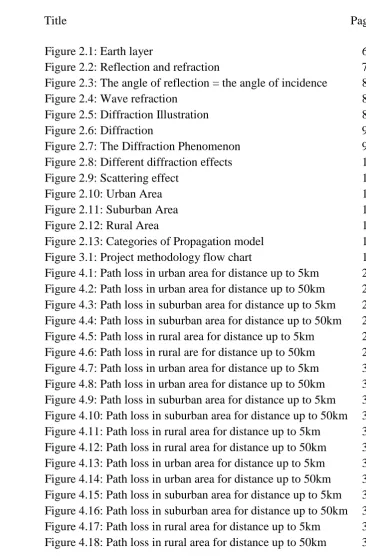
propagation may be specified as figure below. The troposphere is the first layer
above the earth surface, it contains almost half of earth’s atmosphere and which
weather takes place. The troposphere is the region up to a height of 8 up to 10 km
from earth’s surface. The percentage of gas vapor remains constant with increase of
height, but the water vapor component reduced significantly with height. In
troposphere or space wave propagation the EM waves transmitted by transmitting
antenna reach the receiving antenna either directly or after reflecting from the earth
surface in the troposphere region within 16 km above the earth surface. The space
wave at the receiver is constituted of direct ray from the transmitter and reflected ray
from earth. Both wave reach the receiver at same time but may have same phase or
out of phase as they travel different path.
Next is the ionosphere, where ions and electrons exist in sufficient quantities
to refract and/or reflect the electromagnetic radio waves. Ionosphere is the upper part
of the atmosphere where the ionization is appreciable. The upper part of atmosphere
absorbs larger quantity of radiant energy from the sun. This not only heats the
6
Figure 2.1: Earth layer
The propagation of a radio wave through some physical environment is
effected by various mechanisms which affect the fidelity of the received signal.
Accurate prediction of these effects is important in the design and development of a
communications system. These effects can include shadowing and diffraction caused
by obstacles along the propagation path, such as hills or mountains in a rural area, or
buildings in a more urban environment. Reflections off obstacles or the ground cause
multipath effects and the radio signal can be significantly attenuated by various
environmental factors such as ionospheric effects, propagation through vegetation
such as in a forest environment, or reflection from an impedance transition such as a
river or land/sea interface. When line-of-sight (LOS) propagation is not present these
environmental mechanisms have the dominate effect on the fidelity of the received
signal through dispersive effects, fading, and signal attenuation.
The mechanism of electromagnetic waves propagation generally be attributed
to reflection, diffraction and scattering. Most of wave propagation radio system
operates with non line of sight path between the transmitter and the receiver and
which the presence of high buildings causes severe diffraction loss. Besides that, due
to multiple reflections from various objects, the electromagnetic waves travel along
different paths of various lengths. The interaction between these waves causes
multipath fading at a specific location and decreases the strengths of the waves as the
increasing distance between transmitter and receiver.
Reflection, diffraction and scattering are the three basic propagation
mechanism that effect on the wave propagation. It depends on the wavelength
7
energy is transmitted into the second medium and the other is reflected back into the
first medium.
Then, there is no loss of energy in absorption. If the second medium was a
perfect conductor, there has no loss of energy due to all the incident energy is
reflected beck to the first medium. The reflection coefficient is a function of the
material properties, and generally depends on the angle of incidence, wave
polarization and the frequency of the wave propagation.
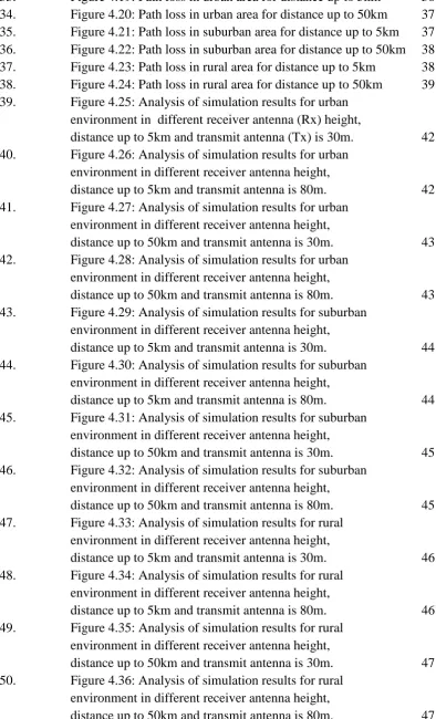
When electromagnetic wave propagates, it experiences a reflection due to object
of the environment is large enough compared to its wavelength. Reflection created
from many sources like the ground surfaces, the walls and from equipments. The
co-efficient of reflection and refraction depends on angel of incident, the operating
and a line perpendicular to the boundary, also on the same side of the surface. Due to
the change of air temperature the density of atmosphere is changed, if a wave is
8
Figure 2.3: The angle of reflection = the angle of incidence
If the incident medium has a lower index of refraction then the reflected wave
has 1800 phase shift upon reflection. Conversely, if the incident medium has a larger
index of refraction the reflected wave has no phase shift.
Figure 2.4: Wave refraction
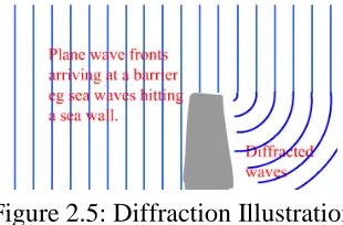
2.3Diffraction
Diffraction occurs when the wave path between the transmitter and receiver is
obstructed by a surface that has sharp edges. Diffraction is the bending of a wave
around objects or the spreading after passing through a gap. The secondary wave
resulting from the obstructing surface is present throughout the space. Even behind
the obstacle has giving rises to bending of waves around the obstacle whereas
between transmitter and receiver, a line of sight path does not exist.
Figure 2.5: Diffraction Illustration
Same as reflection, in the high frequency diffraction depends on the
geometric of the object such as phase, amplitude and polarization of the incident
9
infinite in extent. If this wave passes through an opening, called an aperture, it will
diffract, or spread out, from the opening. The degree to which the cropped wave will
spread out depends on the size of the aperture relative to the wavelength. In the
extreme case where the aperture is very large compared to the wavelength, the wave
will see no effect and will not diffract at all. At the other extreme, if the opening is
very small, the wave will behave as if it were at its origin and spread out uniformly
in all directions from the aperture. In between, there will be some degree of
diffraction.
Figure 2.6: Diffraction
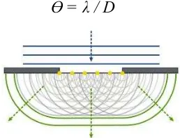
First consider a circular aperture. If a wave with wavelength, λ encounters an
opening with diameter D, the amount of diffraction as measured by the angle, Ɵ ,at
which the new wave diverges from the opening, measured from edge to edge, will be
approximated by :
Ɵ= λ / D
Figure 2.7: The Diffraction Phenomenon
When the link distance is greater than the LOS distance, or when a natural or
man-made obstacle blocks the direct path, there still may be a useful amount of
signal power in the shadow zone at the receiver by the phenomenon of diffraction. Huygen’s principle states that any wavefront can be decomposed into a collection of point sources. New wavefronts can be constructed from the combined
“spherical wavelets” from the point sources of the old wavefront. According to
10
shown in figure below. It is also fairly straight forward to account for the laws of
reflection and refraction using Huygens Principle.
Figure 2.8: Different diffraction effects
A commonly used technique in predicting path loss from terrain obstacles is
knife-edge or Kirchhoff diffraction. Based on Huygen’s principle, the obstacle is
represented by a blocking screen and the field distribution across the resulting
aperture (from the top of the screen, vertically to infinity) integrated to produce the
diffracted fields. The technique is a 2-D method (does not account for oblique
incidence) and assumes that both the source and observation are very distant from the
obstacle. It is a scalar method (does not account for polarization effects) and cannot
account for surface effects such as reflected fields or creeping waves. Also it does
not account for the impedance of the surface.
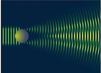
2.4Scattering
Scattering occurs when the medium through which the wave travels consists
of objects with dimensions that are small compared to the wavelength and where the
number of obstacles per unit volume is large. Scattered wave are produced by rough
surfaces, small objects or by other irregularities in the channel. In real phenomenon,
foliage, street signs and lamp posts induce scattering in wave propagation. The actual
received signal in wave propagation is often stronger than what is predicted by
reflection and diffraction. This is due to when wave are struck on a rough surface, the
reflected energy is spread out in all directions due to scattering. An object around
such as lamp posts and tree tends to scatter energy in all direction so it will provide
11
surfaces have much larger dimension than a wavelength. However, the roughness of
such surfaces often induces propagation effect different from the specula reflection.
The requirement that there be many scattered present means that Rayleigh
fading can be a useful model in heavily built-up city where there is non-line of
sight between the transmitter and receiver and many buildings and other
objects attenuate, reflect, refract, and diffract the signal.
The scattering of plane waves from a flat boundary between two media is a
typical canonical problem, where analytical solutions are straightforward and
well-known. It is an idealized case: all real surfaces are rough. The scattering problem will
then depend on the ‘roughness’ of the surface, and exact analytical solutions will not
be generally available.
Figure 2.9: Scattering effect
2.5Effects of Base Station Antenna Height
Propagation characteristics of smart antenna systems can be described by
vector channels. In order to accurately characterize and model vector channels,
extensive measurements in realistic wireless environments are needed. Variation of
vector channels in non-stationary propagation environments which are caused by
deploying the base station antenna at different heights and keeping the mobile
terminal stationary and fixing the base station antenna height and moving the mobile
terminal. Measurements of vector channel parameters in a non-line-of-sight (NLOS)
environment are with a uniform circular array at the base station.