DESIGN A NOVEL THRUSTER MAGNETISM MOTOR (TMM) FOR UNDERWATER VEHICLE APPLICATION
MUHAMMAD NUR BIN OTHMAN (PRINCIPAL)
MOHD SHAHRIEEL BIN MOHD ARAS
FADILAH BIN ABD AZIS
MOHD FARUQ BIN ABDUL LATIF
AHMAD NIZAM BIN JAMALUDIN
PJP/2012/FTK (1B) – S00923
FAKULTI TEKNOLOGI KEJURUTERAAN
ii
SEPTEMBER 2013
“We hereby declared that this report is a result of our own work except for the excerpts that have been cited clearly in the references.”
Signature :
iii
ACKNOWLEDGEMENTS
Alhamdullillah, we are grateful to ALLAH SWT on His blessing in completing this project.
We wish to express our gratitude to honorable our University (Universiti
Teknikal Malaysia Melaka) especially higher management for giving a support and
budget. And also would like to thank UNIC because their tolerance for complete this project successfully.
We would also wish to extend our gratitude to our parents and family for their support and their understanding. And of course to all our friends that help us in this project.
iv
ABSTRACT
v
2.2 Remotely Operated Vehicle (ROV) Classification ... 4
2.3 Thruster ... 6
2.3.1 Thruster Design ... 6
2.3.2 Thruster Power ... 7
2.3.3 Thruster Model in Industry ... 8
vi
3.3.5 Thruster Housing ... 23
3.3.6 Propeller ... 24
3.3.7 Power Supply... 24
3.4 Mechanical Construction ... 24
3.4.1 Motor ... 25
3.4.2 Magnet Holder ... 26
3.4.3 Plate Motor ... 26
3.4.4 Plate Propeller ... 27
3.4.5 Shaft ... 29
3.4.6 Shaft Holder (Wooden) ... 30
3.4.7 Housing for Motor ... 31
3.4.8 Housing for Propeller ... 33
3.4.9 Propeller ... 34
3.4.10 Fabrication ... 35
RESULT, ANALYSIS AND DISCUSSION ... 39
4.1 Motor Speed Test ... 39
4.2 Magnets and different Contactless Air Gap ... 40
4.3 12 Magnets and different Contactless Gap ... 43
4.4 16 Magnets and different Contactless Gap ... 44
CONCLUSION AND RECOMMENDATION ... 46
5.1 Conclusion ... 46
5.2 Recommendation ... 47
vii
LIST OF ABBREVIATIONS
ROV - Remotely Operated Vehicle UUV - Ummanned Underwater Vehicle AUV - Automated Underwater Vehicle CAD - Computer Aided Design
CFD - Computational Fluid Dynamic Cd - Coefficient of Drag
DC - Directional Current PM - Permanent Magnet
VRPM - Variable Reluctance Permanent Magnet RPM - Revolution Per Minute
1 CHAPTER 1
INTRODUCTION
This chapter describes the project background, problem statement, objectives and scope of the project. Problem statement explains about the problem occurred based on previous Research of Remotely Operated Vehicle (ROV) thruster by Underwater Technology Research Group (UTeRG) from Faculty of Electrical Engineering, UTeM. Project objective is the description of the result and goal of this project. Project scope explains the limitations and boundaries of this project.
1.1 Introduction
2 1.2 Project Background
This project is designed a magnetic contactless for underwater thruster which is to demonstrate the movement of the thruster by using magnetic contactless system. The project is to show the performance between the magnetic contactless system thruster and previous thruster of UTeRG in term of speed.
1.3 Problem Statement
3 1.4 Objective
The objectives of this project are:
1. To design a Thruster Magnetism Motor (TMM) for unmanned underwater vehicle application.
2. To study the contactless gap within two magnets at the separate body which has given good performances.
3. To analyze the speed of a contactless magnetic system of underwater thruster and its compatibility on the UTeRG Remotely Operated Vehicles (ROVs).
1.5 Scope of project
The scopes and limitations of this project are:
1. Design and fabricate a prototype of magnetic contactless thrusters. 2. The contactless gap is set up at 21mm, 24mm, 27mm and 30mm.
3. The rare magnetic material (Neo Magnet) with 1.0-1.4 T of magnetic field is used.
4. The maneuverability is only on forward motion. 5. The depth of testing the prototype is 1 meter deep.
6. The testing environment is controllable which is laboratory pool and a swimming pool.
4 CHAPTER 2
LITERATURE REVIEW
2.1 Introduction
This chapter will detail about ROVs and will be focused on thrusters, literature review on the parts and the system used in this project which is magnetic contactless thrusters. It includes explanation of individual character and advantages of particular of components that used in this project. This chapter will explain about ROVs, thrusters, propeller, magnetic principle and the basic design for the thrusters.
2.2 Remotely Operated Vehicle (ROV) Classification
5
Table 2.2: The types of ROVs class
The performance of the thrusters includes the speed of the ROV move either vertical or horizontal axis. The speed is calculated or measure in velocity by use relationship between distance travels over time taken.
(1)
where,
V= Velocity
x=Distance travel [m]
6 2.3 Thruster
The thrusters are commonly used as underwater vehicle’s main propulsion device. It enables the vehicle to perform maneuvers in horizontal or vertical axis [9]. The thrusters consist of the motor, propeller, and housing.
2.3.1 Thruster Design
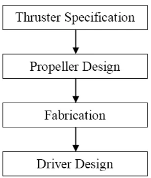
The thruster should produce good results. The thruster is comprised of propellers driven by a motor [10]. But as state before, this project is designing a new design of thrusters which is magnetic contactless thrusters. There are a few major steps for design of these thrusters. They are enumerated as follows [5]:
i. Determination of Technical requirement, 3D CAD Drawing.
ii. CFD (Computational Fluid Dynamic) analysis for performance prediction [8].
iii. Finite Element Analysis of construction strength. iv. Detail Drawing and manufacture.
v. Testing.
7
Figure 2.3.1: Design process flow chart
2.3.2 Thruster Power
Thrusters’ power originally suspected as the most sensitive factor in determining the size and performance of an ROV. Dissimilar aspects of the performance conditions are analyzed in terms of the required thruster’s power [12]. The power necessary for the thrusters is in terms of the total fluid power, and do not include efficiency losses from the propeller and drive train. These factors are measured during motor selection. The drag force F on the ROV is determined by the coefficient of drag, Cd, the surface area, A, and velocity, v.
(2)
The drag coefficient is empirically determined using the above formula. The Reynolds number is a relation between the fluid density p, velocity, U, length, L, and fluid viscosity.
(3)
The maximum steady-state speed for ROV is a function of the max motor power output P for the thruster motors [8] [13].
8 2.3.3 Thruster Model in Industry
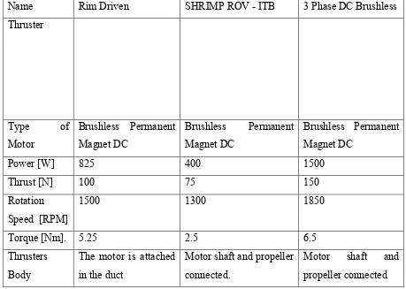
There are a lot of thrusters have been made in nowadays. The designing of the thrusters is made to overcome the problem in underwater industry and create a better performance as customer demand. Table 2.2 shows the type of thrusters that available in the underwater industry [5] [11] [14].
Table 2.3.3: The type of thrusters that available in underwater industry
Name Rim Driven SHRIMP ROV - ITB 3 Phase DC Brushless
9 2.4 Motor
Motor come in many size, shape, and technology, as well as each designed for different uses. The thruster motor on ROV systems is selected based on its availability, power, reliability, variety, and ease of interfaces [15]. The motor is the part in thrusters that influenced the thruster’s performance. The motor drives its shaft to move the propeller hence the thrusters. There are several types of motor that commonly use in ROV thrusters. The motor is selected by its ability to give out higher torque and speed. Lower power consumption also must be considered in selection of motor for reducing the maintenance cost.
2.4.1 Type of Motor
10
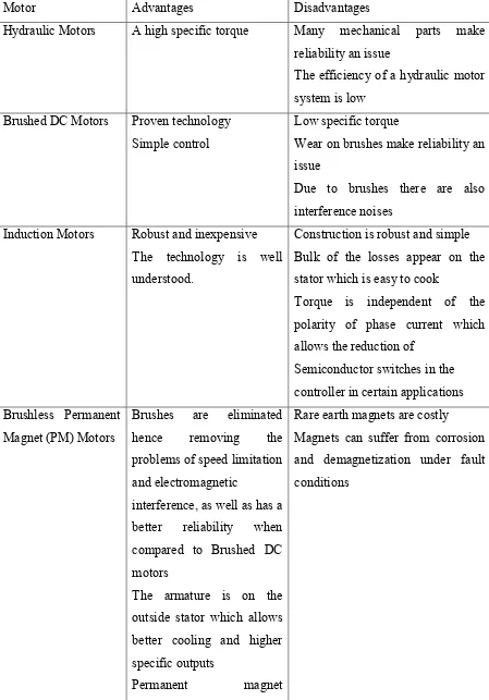
Table 2.4.1: Comparison of various motor needs in underwater industry technologies.
Motor Advantages Disadvantages
Hydraulic Motors A high specific torque Many mechanical parts make reliability an issue outside stator which allows better cooling and higher specific outputs
Permanent magnet
11
excitation reduces rotor losses and improves efficiency
Variable Reluctance A high specific torque Suffers from high axial flux losses Technology is not well understood
Advances made in permanent magnet material and alternative electric motor topologies have made the use of all-electric thruster systems feasible. Electric motors can now be designed to have similar efficiencies and torque outputs for a much smaller size compared to traditional electric motors, albeit at a significant increase in cost if expensive rare earth magnets are used. There are many advantages to the use of electric thruster systems. Electric motors used for thruster systems have a linear response of torque to control signal when compared to hydraulic motors that have dead bands at low velocities. In conclusion, the most suitable motor is the Brushless Permanent Magnet (PM) Motors due to the elimination of brush hence removing the problems of speed limitation and electromagnetic interference, as well as having a better reliability when compared to brush DC motors. The permanent magnet excitation can reduce rotor losses and will improve the efficiency. So this motor will produce higher torque and rotation speed of the shaft.
2.5 Propeller
The propeller is a turning lifting body which is designed to move and vector water opposite to the way of motion [4]. Propeller gives effect to the efficiency of the thruster. There are two types of propellers which are:
1. Ducted Propeller
12
Thruster propeller is designed by which their efficiency is much higher in one direction mostly, often in the forward and the down ways than in the other. Propellers have a nominal speed of max efficiency, which is confidently near the vehicle’s normal operating speed. While selecting a propeller, decide one with the ROV’s operating envelope in mind. Besides that, the size of propeller is directly proportional to speed [6].
Table 2.5: Types of propeller
Table 2.5 shows that the ducted propeller is more efficient than un-ducted propeller. The duct is able to increase the water flow rate through the propeller.
2.6 Magnetic Principle
13
put in one place. The attraction between the two magnets or movement is produced by magnetic fields. A permanent magnet is an item made from a substance that creates its own persistent magnetic field. The end of a freely pivoted magnet will always point in the North-South direction. The end point at the North is called the North Pole of the magnet and the end point south is called the South Pole of the magnet. It has been established by experiments that similar to magnetic poles repel each other whereas unlike poles attract each other [14].
Figure 2.6: Force between two magnets
The magnetic objects like pieces of iron, steel, nickel and cobalt. Magnetic materials also know as ferromagnetic materials. Ferromagnetic materials are divided into two groups which are soft materials which are can be magnetized but do not have a tendency to stay magnetized and hard materials which are can be magnetized but do have a tendency to stay magnetized. The general strength of a magnet is measured by its total magnetic flux that produces by itself. The strength of magnetism is measured by its magnetization.
2.6.1 Magnetic Analysis
In a non-contact system, a permanent magnet is used to produce a magnetizing field strength H (Nm). A magnetic flux density B (T) is produced by the field [3].
(5) Where,
14
Magnetizing field strength H based on the internal magnetism, which is measured by magnetization M which vanishes in non-magnetic materials.
M= πH (6)
Where,
The susceptibility of the material. In all units, it is convenient to employ two types of magnetic field, B and H, as well as the magnetization M, defined as the magnetic moment per unit volume [13].
i. The magnetic flux density (B) is given in units of teslas (T). B is the magnetic field, whose time variation produces, by Faraday’s Law, circulating electric fields. Magnetic field also produces a deflection force on moving charged particles. The T is equivalent to the magnetic flux (in Webers) per unit area (in meters squared), thus giving B the unit of a flux density.
ii. The magnetic field intensity H is given in units of ampere-turns per meter (A-turn/m). The turns appear because when H is formed by a current carrying wire, its value is proportional to the number of turns of that wire.
15
The thruster system works based on the electric machines (DC motor) which rotate about an axis which is known as the shaft. Due to a rotational nature of machinery, a basic understanding of rotational motion is important to have in mind. In this thruster system the shaft is contact with a plate that contains a magnet. The speed of the plate is calculated in angular velocity. Angular velocity or speed is the rate of change in angular position in angular position with respect to time [15].
(8)
Where,
: Angular velocity [rad/s] : Angular velocity [rev/s] : Angular velocity [rev/m]
These measures of rotation speed are related to each other by the following equations:
(9)
(10)
The torque is now calculated when force is applied to the point and the smallest distance between the line of action of the force and the object's axis of rotation. If r is a vector point from the axis of rotation to the point of the force, and if F is the applied force, then the torque can be described as:
(11)
Newton’s law of rotation, is given by the equation
(12)
Where,
16
Moment of inertia Angular acceleration is a measure of the rate of change in angular velocity with respect to time.
(13)
Work is the application of a torque through an angle in rotational motion. Below is the equation for work is:
∫ (14)
If the torque is constant,
(15)
From the torque, the power can be calculated by using the equation:
(16)
(17)
Where,
P = Power [W]
V =Voltage [V]
17 CHAPTER 3
METHODOLOGY
3.1 Introduction