i Faculty Of Electrical Engineering
Universiti Teknikal Malaysia Melaka
DESIGN A UP SIDE DOWN ROBOT GRIPPER SITI ZULAIHA BINTI YUSOFF
ii “I hereby declared that I have read through this report and found that it has comply the partial fulfillment for awarding the degree of Bachelor of Electrical Engineering
(Power Electronic and Drive)
Signature : ………
Supervisor’s Name : EN FARIZ BIN ALI @ IBRAHIM
iii “I hereby that this report is a result of my own work except for the excepts that have
been cited clearly in the references”
Signature : ………
iv ABSTRACT
v ABSTRAK
TABLE OF CONTENT
LIST OF APPENDIX viii
INTRODUCTION The Similarities Case Study
7 8
2.2.2 Canada Arm 2.2.3 Articulated Robot 2.2.4 Vision Arm
4.1.1 Input And Output Pin Overview 4.1.2 Input/output pin configuration
PIC16F877A Basic Circuit 4.2.1 Power Supply 4.2.2 Oscillator
Software
V
5.3 Hardware Development 35
VI
6.1
RESULT AND DISCUSSION
Operation Of Up Side Down Robot Gripper 38
LIST OF FIGURE
Flowchart of Development Project Canada Arm
PIC Input/Output Pin Overview PIC Basic Circuit
Voltage Regulator, Convert 9V- 5V
Suggestion Connection On The Microcontroller Program In Micro C Software
DC Motor Control Simulation Running Light Simulation Project Simulation
DC Motor Driver Circuit
Voltage Regulator 9V-5V Circuit Type Of Battery
Battery Chassis Body
5.7
Connection In The Joystick Controller
Connection From Joystick To PIC Basic Circuit Wheel Attached With Power Window Motor
The Rod Screw Attached With Power Window Motor Gripper Attached With Power Window Motor
Gripper Part Attached With Rotation Part Right View
Front View Robot Controller
LIST OF TABLE
NO TITLE PAGE
1 CHAPTER I
INTRODUCTION
1.1 Introduction
Nowadays, robot is not something foreign in industries technology. Robot is usually using in industries technology especially in heavy industries. Robot is popular by replacing human to do some work which is dangerous to do by human, for example is chemical work, Electro Static Discharge (ESD) working area, lift heavy thing and many more. So, when using the robot we can do everything without any obstacle. The chemical work will bring unhealthy environment and threaten our operator when handle the chemical work. It gives some trouble when they have to lift for mixed up the chemical in the mixture for produce product. Its look simple work, but the work is danger for human. In other case, it will bring bad feedback for human body. The above case bring uncomfortable and danger situation on the working area. The up side down robot gripper is design for liquid pour application. The special criteria for this robot compare with others gripper robot is this robot can rotate the wrist and pour liquid. The other gripper robot only can move up side down and grip thing. The function of this robot is lift up and pour the liquid. Besides that, the up side down robot gripper also can move forward and backward. Through this robot,
2 1.2 Problem Statement
Robot is usually using in industries technology especially in heavy industries. And it is also popular by replacing human to do some work which is dangerous to do by human, for example is chemical work, Electro Static Discharge (ESD) working area, lift heavy thing and many more. In real life, the gripper robot is used for liquid pour application. From the previous gripper robot, the robot wrist cannot rotate and the liquid cannot pour. To solve this problem, the up side down robot gripper is design. The special criteria for this robot compare with others are this robot can rotate the wrist 180 degree to pour the liquid. The another robot gripper only can move up side down and grip thing. With this improvement, the liquid pour application will be improve and make our heavy lift work become easy and also to complete the task for Robocon to score point easily.
1.3 Objective
The objective of this project is :
To improve the liquid pour application in the industrial sector.
To make our heavy lift work become easy.
To complete the task for ROBOCON to score point easily.
To design new robot for lift thing application.
To study and design the PIC16F877programming for software and hardware for microcontroller.
To gain experience in system design, hardware and software design, electrical and mechanical drawing, wiring, troubleshooting and documentation.
3 1.4 Scope of Project
The scope of this project is divided by two parts, the hardware and the software. The hardware involves designing the mechanical part and electrical part for up side down robot gripper. The mechanical part involves the chassis, and the electrical part involves in microcontroller and driver circuit. The software involves designing and writing the program for the robot to move forward, backward, left, right, up, down and grip.
1.5 Methodology
1) Collecting information i. PIC function ii. Operation method
iii. Understand Software C- language
2) Circuit development i. PIC basic circuit ii. Driver motor circuit
3) Design and develop the robot model i. Design the gripper
4 4) Software development
i. Do flowchart for operation of robot ii. Design the program using C- language
5) Combine the software and robot model i. Burn the program in the PIC16f877A IC ii. Wiring the robot
iii. Connect the driver circuit with motor
6) Testing
i. Testing and define the problem when combine the software and hardware.
7) Provide final report
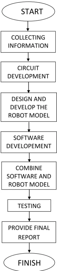
5 The development project flowchart
Figure1.1: Flowchart of development project
START
COLLECTING
INFORMATION
CIRCUIT
DEVELOPMENT
DESIGN AND
DEVELOP THE
ROBOT MODEL
SOFTWARE
DEVELOPEMENT
COMBINE
SOFTWARE AND
ROBOT MODEL
TESTING
PROVIDE FINAL
REPORT
6 CHAPTER II
LITERATURE REVIEW
2.0 Introduction
The term robot comes from the Czech word robota [1], generally translated as
7 2.1 Gripper Robot Background
Robots which must work in the real world require some way to manipulate objects; pick up, modify, destroy or otherwise have an effect. Thus the 'hands' of a robot are often referred to as end effectors, while the arm is referred to as a
manipulator [3]. Most robot arms have replaceable effectors, each allowing them to perform some small range of tasks. Some have a fixed manipulator which cannot be replaced, while a few have one very general purpose manipulator, for example a humanoid hand.
Grippers: A common effectors is the gripper. Usually it consists of just two fingers which can open and close to pick up and let go of a range of small objects.
Vacuum Grippers: Pick and place robots for electronic components and for large objects like car windscreens, will often use very simple vacuum grippers. These are very simple, but can hold very large loads, and pick up any object with a smooth surface to suck on to.
8 2.2 The Similarities Case Study
2.2.1 SCARA robot
The SCARA acronym [4] stands for Selective Compliant Assembly Robot Arm or Selective Compliant Articulated Robot Arm. In general, traditional SCARAs are 4-axis robot arms, i.e., they can move to any X-Y-Z coordinate within their work envelope. There is a fourth axis of motion which is the wrist rotate (Theta-Z). The
„X‟, „Y‟ and the „Theta-Z‟ movements are obtained with three parallel-axis rotary joints. The vertical motion is usually an independent linear axis at the wrist or in the base. SCARA robots are used in assembly operations where the final move to insert the part is a single vertical move. Component insertion into printed circuit boards is an example. This is often called "vertical assembly". They are very common in pick-and-place, assembly, and packaging applications. The electronic printed circuit board industry, in particular, use large numbers of SCARAs for placing semiconductor ICs and other components on the circuit boards of computers and related equipment.
The second attribute of the SCARA is the jointed two-link arm layout similar to our human arms, hence the often-used term, Articulated. This feature allows the
arm to extend into confined areas and then retract or “fold up” out of the way. This is
9 2.2.2 Canada Arm
The “Canada hand” resembles a headless torso fitted with two extremely agile, 11 fit long arms and several smaller appendages [5]. The 12 ft long “torso” pivots at the “waist”. The “torso” has a grapple fixture at one end that can be grasped by the larger Space Station Arm, Canadarm2 so that the SPDM can be positioned at the various Orbital Replacement Unit (ORU) worksites along the Space Station trusses. The other end of the “torso” has a grasp fixture virtually identical to that of Canadarm2, so that the SPDM can be stored on Space Station grapple fixtures or can be used as an extension to the larger arm.
The two SPDM arms each have seven, specially offset joints giving a greater freedom of movement in a smaller package than previous systems. At the end of each of these arms is a system called the Orbital Replacement Unit/Tool Change out Mechanism (OTCM). It has built-in grasping jaws, a retractable socket drive, a monochrome TV camera, lights, and an umbilical connector that can provide power and data, and receive video, to/from a payload. The lower “torso” of Dexture has a pair of Orientale color TV cameras with lights, an ORU platform, and tool holders.
10 2.2.3 Articulated Robot
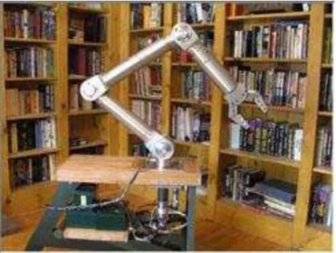
An articulated robot is a robot with rotary joints (e.g. a legged robot) [6]. Articulated robots can range from simple two-jointed structures to systems with 10 or more interacting joints. They are powered by a variety of means, including electric motors. Some types of robots, such as robotic arms, can be articulated or non-articulated
Figure 2.3 : Articulated Robot
2.2.4 Vision Arm
11 As more experience is generated and archived in development and experimentation with the image system, the more capable the VisionArm™ system will become in performing autonomous and/or unattended activity. Further specifications for the arm and control electronics are included in the tables below.
12 CHAPTER III
METHODOLOGY AND RESEARCH
3.1 General Methodology
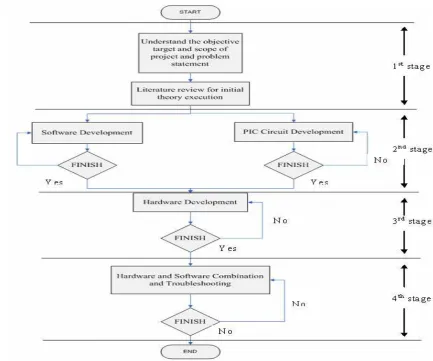
To develop the up side down robot gripper, there are some method that all objective of this project successfully archive. The main sub is literature review, hardware development and software development. The flowchart below demonstrate the approach used in completing the project. The methodology of this project is divided by 3 stage.
Stage 1: Understand the objective target, scope of project and problem statement. Do literature review for initial theory execution.
Stage 2: PIC circuit development and software development.
Stage 3: Hardware development, Combination hardware, software and troubleshooting.
13 continue to next stage. If not finish, we need to repeat the process again. In the stage 3, need to develop the hardware. Design and construct the chassis of up side down robot gripper. If finish, we can go to next step, if not we need to repeat the process again. After settle hardware development, the hardware and software will combine and troubleshooting. This stage is the final stage to make sure the project is
successfully function or not. This stage also the difficult stage because we need to combine the hardware and software. After troubleshooting, if no problem occur, the combination is pass and the robot can function. If no, we need to check the error. We will check back the software and hardware design until we get the result we want.