“I hereby declared that I have read through this report entitle “Vision-Based Mobile Robot” and found that it has comply the partial fulfillment for awarding the Bachelor of Mechatronic Engineering.”
Signature : ………
Supervisor’s Name : Mr. Muhammad Herman bin Jamaluddin
VISION-BASED MOBILE ROBOT
LOKE WENG HONG
This Report is Submitted in Partial Fulfillment of Requirements for Bachelor of
Mechatronic Engineering.
Faculty of Electrical Engineering
UNIVERSITI TEKNIKAL MALAYSIA MELAKA
“I declare that this report entitle “Vision-Based Mobile Robot” is the result of my own research except as cited in the references. The report has not been accepted for any degree and is not concurrently submitted in candidature of any other degree.”
Signature : ………
Name : Loke Weng Hong
iv
ACKNOWLEDGEMENTS
The success of any project as extensive as this one involves the contributions and support of many people. There were many people that I would like to thank and appreciate for their support, guidance and cooperation with me upon the completion of Final Year Project (FYP).
First of all, I would like to take this opportunity to thank UTeM for offering me the course Bachelor of Mechatronic Engineering. The first person I would like to give special recognition and sincerest appreciation is Mr. Herman bin Jamaluddin for his indiscrimination toward me and taking over Mr. Ahmad Zaki bin Shukor as my supervisor. I would also like to thanks for his relentless support and valuable guidance. His patients in giving advices, comments, and suggestions are really useful and supported me through the whole period of FYP. His words encouraged me to overcome any difficulty and obstacles faced during FYP. Beside that, I also want to give my appreciation to my FYP panels, Mr. Aminurrashid Bin Noordin and Mr. Ahmad Idil Bin Abdul Rahman for good cooperation, opinions, and information for my FYP project during FYP 1 seminar. Not forgetting Mr. Omar Bin Mat Ibrahim for giving me support through the whole fabrication of FYP mechanical structure at the Faculty of Electrical Engineering in UTeM.
I also wish to dedicate this project to my family who has given me strength and moral support until the end of this semester. Last but not least I would like to thank those individuals who have been directly and indirectly involved and generously shared their knowledge and idea in order to complete this FYP report.
v
ABSTRACT
vi
ABSTRAK
vii
TABLE OF CONTENTS
`CHAPTER TITLE PAGE
ACKNOWLEDGEMENTS iv
ABSTRACT v
ABSTRAK vi
TABLE OF CONTENT vii
LIST OF TABLE x
LIST OF FIGURE
LIST OF APPENDICES
xi
xiii
ABBREVIATION xiv
1 INTRODUCTION 1
1.1 Project Overview 1
1.2 Project Objective 2
1.3 Project Scope 2
1.4 Problem Statement 3
2 LITERATURE REVIEW 4
2.1 Introduction 4
2.2 First Review : Qualitative Vision – Based Mobile Robot Navigation
4
2.3 Second Review : Vision – Based Mobile Robot Navigation using Fluorescent Tubes
7
viii
CHAPTER TITLE PAGE
2.5 Fourth Review : Minerva – Museum Tour Guide Robot 9
3 METHODOLOGY 12
3.1 Introduction 12
3.2 Process Flow Chart 12
3.3 Literature Review/ Technical Research 15
3.4 Design and Establish Mechanical Structure 15
3.5 Interfacing CMOS camera with Computer 15
3.6 Interfacing Microcontroller with Computer 16
3.7 Implementing Line Recognition Using CMOS Camera and Microcontroller Under Different Lighting Condition and Background Color
16
3.8 Implementing CMOS Camera for Item Recognition and Navigation Through Obstacles
16
4 RESULTS 18
4.1 Introduction 18
4.2 Microcontroller PIC16F877A 18
4.2.1 Simulation Using Proteus 7 Professional 19
4.3 CMUcam3 23
4.3.1 Interfacing with Computer 27
4.4 Mobile Robot Structure 32
4.4.1 Mechanical Structure 32
4.4.2 Electrical Circuit 34
5 ANALYSIS AND DISCUSSION 35
ix
CHAPTER TITLE PAGE
5.2 Microcontroller PIC16F877A 5.3 CMUcam3
5.4 Performance of Vision-based Mobile Robot
35 37 39
5.4.1 Effect of DC Brushless Motor Speed 40
5.4.2 Effect of Different Color Background and Line 41
5.4.3 Effect of Line Width 43
5.4.4 Effect of Different Lightning Condition 45
6 CONCLUSION AND RECOMMENDATION 47
6.1 Conclusion 47
6.2 Recommendation 48
REFERENCES 49
x
LIST OF TABLES
TABLE TITLE PAGE
3.1 4.1 4.2 4.3 5.1 5.2 5.3
Process Flow Gantt Chart
Power Consumption for CMUcam3 CMUcam3 Components Characteristic
Result of simulation and CMUcam3 Frame Grabber Result of calculation according to Figure 5.2
Result of color recognition ability for high and low resolution Properties of high and low resolution in CMUcam3
xi
LIST OF FIGURES
FIGURE TITLE PAGE
2.1 2.2 2.3 2.4 2.5 2.6 2.7 3.1 4.1 4.2 4.3 4.4 4.5 4.6 4.7 4.8 4.9 4.10 4.11 4.12 4.13 4.14
Position of Mobile Robot for moving methodology. Image capture by camera during moving experiment. Mobile robot with camera pointing at ceiling.
Layout of WMR and host computer in experiment field. Occupancy Map of Smithsonian Museum.
Texture Map of Smithsonian Museum. (a) Minerva (b) Minerva’s motorized face. Process Flow Chart.
Functional Circuit Design in Proteus 7 Professional. CMOS vision of track in different position.
Simulation of mobile robot moving forward. Simulation of mobile robot turning right. Simulation of mobile robot turning left. Motor configuration of mobile robot. CMUcam3 major components
Process of major components in CMUcam3 General layout of CMUcam3 connection pin Serial port layout of CMUcam3
CMUcam3 Frame Grabber
Mobile robot facing forward along the red line
CMUcam3 Frame Grabber response when mobile robot facing forward.
Mobile robot straying to the right.
xii
LIST OF FIGURES
FIGURE TITLE PAGE
4.15 4.16 4.17 4.18 4.19 4.20 5.1 5.2 5.3 5.4 5.5 5.6 5.7 5.8 5.9 6.1
CMUcam3 Frame Grabber response when mobile robot straying to right.
Mobile robot straying to the left.
CMUcam3 Frame Grabber response when mobile robot straying to the left.
Solidworks Design of Mechanical Structure
Picture of Established Mechanical Structure (a) Plan view (b) Declivity angle of CMUcam3 (c) Isotropic view
Electrical circuit mounted on mobile robot. (a) Position of electrical circuit on mobile robot. (b) Configuration of components in electrical circuit.
LINIX Brushless DC Motor Drives
CMUcam3 vision of mobile robot straying to left of red line in pixel. Vision-based mobile robot track.
Vision-based mobile robot full speed trajectory. Vision-based mobile robot quarter speed trajectory. Mobile robot trajectory in different background color. Mobile robot trajectory in different line color.
Mobile robot trajectory in line width 5cm Mobile robot trajectory in line width 2.5cm Red object recognition.
xiii
LIST OF APPENDICES
APPENDIX TITLE PAGE
A B C
D
LINIX Brushless DC Motor Drive Datasheet CMUcam3 Datasheet
OmniVision OV6620 CMOS CIF Color Digital Camera Datasheet
PIC16F877A Datasheet
46 49 59
xiv
ABBREVIATION
APS - Active Pixel Sensor
ASCII - American Standard Code for Information Interchange CAD - Computer-Aided Design
CIF - Common Intermediate Format
CMOS - Complementary Metal-Oxide Semiconductor CPU - Central Processing Unit
DC - Direct Current FAT - File Allocation Table FIFO - First In-First Out FPS - Frame Per Second FYP - Final Year Project GUI - Graphical User Interface
Hz - Hertz
IR - InfraRed
JPEG - Joint Photographic Experts Group LED - Light Emitting Diode
LCD - Liquid Crystal Display MMC - MultiMedia Card ns - Nanoseconds
PDIP - Plastic Dual In-line Package PWM - Pulse Width Modulation
RAM - Random Access Memory
RGB - Red-Green-Blue
ROM - Read-Only Memory
xv
ABBREVIATION
1
CHAPTER 1
INTRODUCTION
This chapter will introduce the objective, problem statement and scope of the project of vision – based mobile robot. This project is categorized to three main parts which include electric circuit, mechanical design and microcontroller programming.
The main objective of this project is enabling the automatic mobile robot to follow the desired trajectory such as line tracking according to real-time image from CMOS sensor. For further implementation of other desired trajectory such as landscape image or object can be obtained by comparing reference image with current image taken by CMOS sensor.
The concept of this project is using CMOS sensor for real-time image processing and comparing with reference image. The program can determine movements of mobile robot by differentiate the line color and the background color under different lightings condition.
1.1 Project Overview
Vision-based mobile robot is a project approach for line following of a white tape on different background colors. The vision sensor is a Complementary Metal-Oxide Semiconductor (CMOS) sensor, interfaced with an 8Mbits FIFO independent memory for image buffering and microcontroller for mobile robot movement control.
2 1.2 Project Objective
The main objective of this project is to design and implement a vision-based mobile robot for navigation. To achieve this, the main objective is divided into several smaller and specific objectives as follows;
1. Design and establish basic mechanical structure. 2. To interface CMOS camera with computer.
3. To implement communication between CMOS camera and microcontroller. 4. To implement line recognition using CMOS camera and microcontroller
5. To implement navigation using CMOS camera and microcontroller under different lighting condition and background color.
1.3 Project Scope
The scope of this project is to design and implement a vision-based mobile robot for navigation. This project divides into three main parts which are, mechanical structure, electrical circuit and microcontroller programming.
The mechanical structure designed and establish for differential motor drive. The structure will install with 2 brushless DC motor with driver and 24Vdc battery pack. The support for CMOS APS pixel will be adjustable for further implementation such as object recognition.
3 1.4 Problem Statement
4
CHAPTER 2
LITERATURE REVIEW
2.1 Introduction
This chapter is the summary of the literature review of the article that holds similar concept approach in mobile robot navigation. These articles give example on vision-based mobile robot control system and concept on implementing navigation in vision-based mobile robot.
2.2 First Review : Qualitative vision-based mobile robot navigation
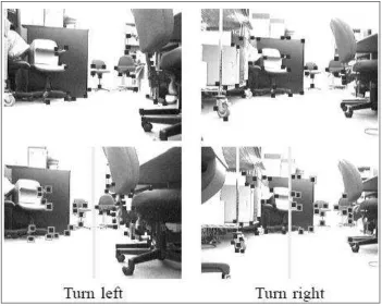
This article is the effort of Zhichao Chen and Stanley T. Birchfield from Electrical and Computer Engineering Department at Clemson University, May 2006. In this article they presented a simple algorithm for mobile robot navigation. Using a teaching-replay approach, the robot is manually led along a desired path in teaching phase, and then the robot autonomously follows the path in the replay phase. The feature points of this article are automatically detected and tracked throughout the image sequence, and the feature coordinates in the replay phase are compared with those computed previously in the teaching phase to determine the turning commands for the robot.
5 noticeable that the destination consist 2 d
i
u at left and 1 d i
u at right (the center of the camera divide the left and right part). If the mobile robot is deviate from the correct path, such as in position A according to Figure 2.1(b), all t
i
[image:20.612.79.543.210.457.2]u is in left part of the camera. Hence, its will turn left to achieve the correct amount of sign before moving forward.
Figure 2.1: Position of Mobile Robot for moving methodology
6
Figure 2.2: Image capture by camera during moving experiment
7 2.3 Second Review: Vision-based Navigation of Mobile Robot using Fluorescent
Tubes
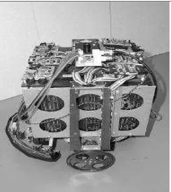
This article is about a vision-based mobile navigation method in an indoor environment for an autonomous mobile robot by Fabien Launay, Akihisa Ohya, Shin’ichi Yuta from Intelligent Robot Laboratory in University of Tsukuba. In this method, the self-localization of the robot is done by detecting the position and orientation of fluorescent tubes which are located above its desired path by a camera pointing to the ceiling.
Fluorescent tube is chosen as the landmark because absolute localization in indoor navigation using landmarks located on the ground or on the walls is not easy since different objects can obstruct them. The advantage of fluorescent tubes compared to other possible landmarks located on the ceiling is that once they are switched on, their recognition in an image can be performed with a very simple image processing algorithm since they are the only bright elements that are permanently found in such a place. Beside that, it is also free from problems such as dirt, shadows, light reflection on ground, or obstruction of the landmarks.
[image:22.612.230.400.485.676.2]The mobile robot will correct its trajectory when a fluorescent tube is found. The mobile robot will position itself parallel with the fluorescent tube before moving to the next fluorescent tube.
8 2.4 Third Review : Path Tracking Laws and Implementation of a Vision-based
wheeled mobile robot
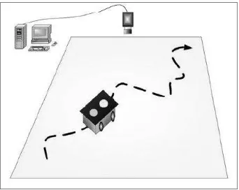
[image:23.612.145.487.317.589.2]This article is written together by Shiao Ying Shing, Yang Jui Liang, and Su Ding Tsair from Department of Electrical Engineering from National Chang-hua University of Education, Taiwan. This article provides an alternative way for vision-based approach navigation. The control objective for the vision-based tracking problem is to manipulate the WMR to follow the desired trajectory. This system is composed of a ceiling-mounted fixed camera whose outputs are connected to a host computer, and a WMR with two atop different color, round marks to differentiate the front and rear of the WMR as show in figure 2.4.
Figure 2.4: Layout of WMR and host computer in experiment field.
9 computer. Then, the host computer will transmit the correction signal via wireless transmitter to the WMR and hence, correct the trajectory of the WMR.
2.5 Fourth Review: MINERVA – A Museum Tour-guide Robot
This article is written by Sebastian Thrun, Frank Dellaert, Dieter Fox, Charles Rosenberg, Nicholas Roy, and Jamieson from School of Computer Science in Carnegie Mellon University, Pittsburgh collaborates with Maren Bennewitz, Wolfram Burgard, Armin B. Cremers, Dirk Hahnel, and Cirk Schulz from Computer Science Department III in Univeristy of Boon, Germany. This article describes Minerva, a mobile robot designed to educate and entertain people in public places.
The movement of Minerva is determines by 2 types of maps, occupancy map and texture maps of the museum ceiling. Both maps are learned from 3 types of sensor data, laser scans, camera images and odometry readings during the learning phase. The occupancy map will be learned first for Minerva desired trajectory, while the texture map is used for real time position confirmation of Minerva.