Hari Penyelidikan Fakulti Kejuruteraan Mekanikal, Universiti Teknikal Malaysia Melaka, 20 Julai 2011
34
Determination of Vibration Strength of a Small Structure-Borne
Source Using a High Mobility Reception Plate
M. Fadzil1, A. Putra2, R. Ramlan2
Abstract– This paper presents the characterization of vibration strength obtained from reception plate method by applying the mobility concepts. It describes a laboratory-based measurement procedure, which determines the strength of a vibration source in terms of the total squared free velocity of the source. The source used in the experiment is the small electric fan motor installed on high mobility aluminum panel in order to neglect the influence of the source mobility. The complexity of the mobilities at the contact points are reduced using the single value of effective mobility. The aim is to validate the data obtained from the reception plate method with one from the direct measurement. A good agreement is found between the two results.
Keywords: effective mobility, reception plate method, squared free velocity, structure-borne source, source-reciever.
I. Introduction
Annoyance due to noise in a building is still one of major problems in engineering. This noise is often caused by vibration from rotating machines which are channeled to the building structure. This then carries the vibrational waves and radiates noise into the air. The most risky structure is the one of industrial or factory building which contains many vibrating machineries, such as the iron and steel industries, foundries, saw mills, textile mills and crushing mills among many others. Those machines are capable of injecting high level of vibration which not only causes noise but also hazardous to the structure where the machines are installed. Such machines which causes propagation of vibrational waves into the neighboring structure is called structure-borne sources.
The vibration effect to a structure is rather vital. The symptom before the structural damage is sometimes not visible. With information of the vibration input power from the sources; preliminary control measure can be planned. For example while planning to install a huge vibrating machine, the supplied
information of the machine’s vibration input
power allows a structural engineer to take preventive action, such as to ensure the support structure is strong enough to absorb the potential vibration power. This will give time to reinforce the structure or install some damper at the certain locations e.g. at the contact points between structure and source [1].
The treatment of structure-borne sound sources remains a challenging problem due to many uncertainties and difficulties. For example, measurement or determination of the force excitation to a building floor, by active components like pumps, compressors, fans and motors, which is an important mechanism of vibration and noise generation and also an important parameter to obtain the potential vibration input power [2].
Hari Penyelidikan Fakulti Kejuruteraan Mekanikal, Universiti Teknikal Malaysia Melaka, 20 Julai 2011
35 behavior of the source-receiver system in the
frequency range of interest [3].
Therefore, rather than to predict the vibration input power in situ, prediction before installation is of interest. This paper presents a laboratory-based method using a reception plate. A small fan motor was used as the vibration source and its input power ‘strength’ was measured. This is represented by the free velocity which is one of parameters to characterize the structure-borne source. The using of effective mobility of the reception plate is also discussed.
II. Mathematical Formulation
II.1. Vibration input power
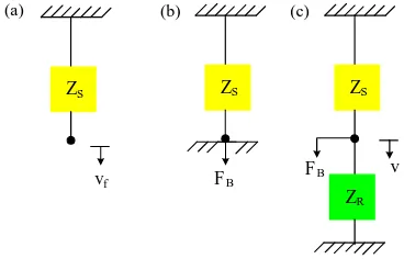
Figure 1(a) shows a diagram of a source
Fig. 1:Mathematical diagram of a vibration source and a receiver.
If the source is then attached rigidly on a rigid surface (Figure 1(b)), the resulted force FB is
called the blocked force. From definition
S
of the source, respectively.
If the source is now connected to a receiver with impedance ZR (Figure 1(c)) and assuming
both the source and receiver move in the same velocity v, the blocked force is the sum of the source-receiver system can be obtained in terms of the properties of the source and receiver
S Assume the source is attached to the receiver through a single contact point, the power injected to the receiver, Pin is defined by
2 power can be expressed as
Eq. (6) can then be simplified and be written as
terms of matrices and vectorsHari Penyelidikan Fakulti Kejuruteraan Mekanikal, Universiti Teknikal Malaysia Melaka, 20 Julai 2011
36 required matrix size is 6N6N. However, in
this paper, only translational force perpendicular to the receiver plane is taken into account. The matrix size then reduces toNN given by
II.2. Reception Plate Method
In this section, the reception plate equation is introduced. Using the reception plate method, a machine under test is attached on a plate under its normal operating conditions [4,5]. The total structure-borne power transmitted is obtained from the measured spatial average of the mean square plate velocity
2 R
in Sm v
P (10) where is the damping loss factor of the plate, S is the plate area, m is the mass per unit area,
2 R
v is the spatially average of mean-squared velocity and is the operating frequency. The damping loss factor can be obtained by
spatially average squared transfer mobilities. From Eq. (8) and (10), by using high mobility
II.3. Effective Mobility
The effective mobility sums the point and transfer mobilities for each contact point to be a
“single mobility” [6,7]. For zero phase assumption, it is expressed as
For random phase assumption, it is given by
2
Hence by using the effective mobility, Eq. (12) can be written as (15) can be further simplified as
Hari Penyelidikan Fakulti Kejuruteraan Mekanikal, Universiti Teknikal Malaysia Melaka, 20 Julai 2011
37 squared free velocity
N i
f
v 2of the tested structure-borne source can now be obtained.
III. Experiment and Results
The experiment was conducted using a table fan motor as the source and an aluminium plate of 1 mm thick and dimensions 1.40.8 m as the receiver. To use Eq. (16), the mobility of the receiver must be much larger than that of the source. Fig. 1 shows the comparison between the measured mobilities of the motor and the receiver using the instrumented impact hammer and accelerometer. It can be seen that on average the plate mobility is 20 dB larger than that of the motor indicating that the source mobility can be neglected in Eq. (12). The measured data are the point mobility of the plate at the contact point location and the mobility of the source at the feet of the motor.
Fig. 1: Comparison between the source and receiver mobilities using in the experiment.
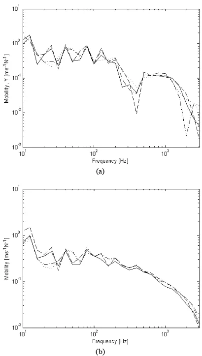
The variations of the effective mobilities are shown in Fig. 2 for zero and random phase assumptions in one-third octave bands.
(a)
(b)
Fig. 2: Effective mobility of the reception plate assuming: (a) zero phase and (b) random phase.
The results show that in general, the variation is within 5 dB for each contact point location at the reception plate.
To obtain the spatially average of
Hari Penyelidikan Fakulti Kejuruteraan Mekanikal, Universiti Teknikal Malaysia Melaka, 20 Julai 2011
38 Fig. 3: The motor attached on high mobility reception plate.
Fig. 4: Measured spatially average of mean-squared velocity of the reception plate.
It can be seen from Fig. 5 that the response dies off above 1.5 kHz. This shows the effective frequency range of excitation given by the motor.
The damping loss factor of the plate (calculated from Eq. (11)) is plotted in Fig. 5 up to 1.5 kHz in one-third octave bands.
Fig. 5: Measured damping loss factor from the reception plate. Finally, the free velocity from the reception
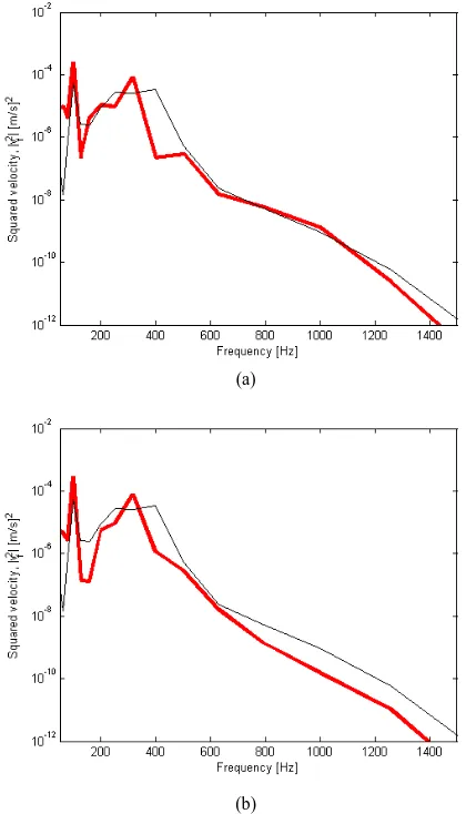
plate method as in Eq. (16) can be obtained. Fig. 6 presents the estimated squared free velocity compared with that from the direct measurement. The latter was conducted by hanging the motor and the velocity was measured at each feet using accelerometer.
(a)
(b)
Fig. 6: Comparison of squared free velocity between that obtained using reception plate method (thick line) and that from direct measurement (thin line): (a). zero phase effective mobility and (b).
random phase effective mobility.
Hari Penyelidikan Fakulti Kejuruteraan Mekanikal, Universiti Teknikal Malaysia Melaka, 20 Julai 2011
39 10 dB above 600 Hz. This indicates that the
excitation phase of the motor might be still in-phase up to 1.5 kHz.
IV. Conclusion
Determination of the vibration strength of a structure-borne source represented by the free velocity has been conducted using a reception plate method with high mobility panel. This is proposed for a mechanical installation to a plate-like structure. A good agreement is achieved for the squared free velocity of the source between the result from the method and that from direct measurement.
Although the method has been applied successfully, there are several factors which might be considered to improve the method. Among many is to investigate the effect of phase excitation and also effect of excitation locations which contribute to the result of plate mobility. Instead of the exact result, the possible range of the vibration strength in terms of its statistical variation across the frequency is of interest.
Acknowledgements
The authors would like to acknowledge Fakulti Kejuruteraan Mekanikal, Universiti Teknikal Malaysia Melaka (UTeM) for supporting this work through the PSM final year project. Also the laboratory technicians for their helps in conducting the experiments are greatly appreciated.
References
[1] Bies, D.A. and Hansen, C.H. Engineering Noise Control: Theory and Practice. London:E&FN Spon, 1996.
[2] Soong. State of the art review: active structural control in civil engineering, Engineering Structures, 1988.
[3] Pieter Schevenels. Identification Of Structure-borne sound paths of service equipment in buildings using structural-acoustic reciprocity. Proceeding of the 16th International Congress of Sound and Vibration, Kraków, Poland, 2009.
[4] M. Spah, B. M. Gibbs, and H.-M. Fischer, New laboratory for the measurement of structure-borne sound power of sanitary installaions, Forum Acusticum, Budapest, 1907 – 1912, 2005. [5] B. M. Gibbs, N.Qi and A. T. Moorhouse, A practical
characterization for vibro-acoustic sources in buildings, Acta Acustica, 93, 84-93, 2007.
[6] B. A. T. Petersson and J. Plunt, On effective mobilities in the prediction of structure-borne sound transmission between a source and a receiving structure, Part 2: Estimation of mobilities, Journal of Sound and Vibration, 82(4), 531-540, 1982.
[7] B. M. Gibbs, R. Cookson and N. Qi. Vibration activity and mobility of structure-borne sound sources by a reception plate
method, Journal of the Acoustical Society of America, 123:4199-4209, 2008.
1Student of Structure & Materials, Faculty of Mechanical Engineering,
Universiti Teknikal Malaysia Melaka, Malaysia.
2Researches at the Vibration and Acoustics Research Group, Faculty of
Mechanical Engineering, Universiti Teknikal Malaysia Melaka, Malaysia
Meor Muhsin Bin Fadzil was born in Wichita, Kansas City, USA on 21st December
1986. He received Diploma of Mechanical Engineering in 2007and is currently final year student pursuing Bachelor of Mechanical Engineering (Structure & Material) in Faculty of Mechanical Engineering, UTeM.
Azma Putra is a senior lecturer in Faculty of Mechanical Engineering, UTeM. He received his Ph.D in 2008 from Institute of Sound and Vibration Research (ISVR), University of Southampton, United Kingdom. His current interests are engineering acoustics and noise control, vibro-acoutics, vibration and structural dynamics.