International Journal of Science and Research (IJSR), India Online ISSN: 2319-7064
Volume 2 Issue 5, May 2013
www.ijsr.net
Design and Development of Amphibious Hybrid
Vehicle Body Structure
Muhammad Zahir Hassan1, Muhammad Razil Razali2, Mohd Shazni Halid3
1
Center of Advanced Research and Energy (CARE), Faculty of Mechanical Engineering, Universiti Teknikal Malaysia Melaka, Malaysia
2
Center of Advanced Research and Energy (CARE), Faculty of Mechanical Engineering, Universiti Teknikal Malaysia Melaka, Malaysia
3
Center of Advanced Research and Energy (CARE), Faculty of Mechanical Engineering, Universiti Teknikal Malaysia Melaka, Malaysia
Abstract: Amphibious vehicle is a concept of vehicle that can be put forward for the purpose of commercialization, especially in the
field of military and rescue operation. This paper present the development process involve in developing the composite bodywork of the Amphibious Hybrid Vehicle (AHV). It involves the process of design followed with the fabrication process. The total design method is used during the selection of the design stage and transformed into 2-dimensinonal and 3-dimensinal form using CATIA V5 software. Upon completion of design, the fabrication process is implemented to complete the bodywork of the amphibious vehicle.
Keywords: amphibious hybrid vehicle, composite
1.
Introduction
Vehicle body design is one of the important aspects for the performance of a vehicle. When the vehicle across a medium at high speed, the medium will acts on the vehicle body in term of resistance [1]. Air is one of the medium of space that provide resistance when vehicle traveling at high speed due to air space densities. This contributes to the consumption of fuel use of for vehicles.
Besides that, the design of the vehicle body should have an aura of attraction to people who see every details of design in terms of creativity and aesthetical value. Therefore, in this paper designs process are documented according to stage which the design is start from scratch. Selection of materials for the manufacture of basic materials is an important vehicle for ensuring that the vehicle is able to float on the water [2]. Among the criteria required material for manufacture of the vehicle is that it must be durable, has good properties of waterproof, easy to set up and easy to do the repairs in the event of damage and maintenance work.
In this project, fiberglass is used to fabricate the body due to the lightweight and the strength of the material [3]. Fiberglass is also a material that can absorb sound effectively due to the properties of the material that has good damping capacity for noise absorption. Fiberglass is most commonly used material for body building of boats or vehicles to cross water due to its mechanical properties and have a good waterproof properties compared to other materials in composite family [4]. To construct the vehicle body with fiberglass, there are several techniques can be used and Hand layup techniques is one of the famous technique that widely used due to it minimum cost and less used of machine which are conventionally executed. This technique is covered in this paper under the fabrication process.
2.
Design process
The design stage process of UTeM’s AHV body is shown in Figure 1. The early stage of the design process is to create a conceptualization idea. Creativity is required to generate the ideas during the conceptualization stage. Brainstorming approach is used to produce as many ideas that are relevant for the AHV specification as described in Table 1.
Figure 1: Shows flowchart of design phase for the amphibious vehicle body.
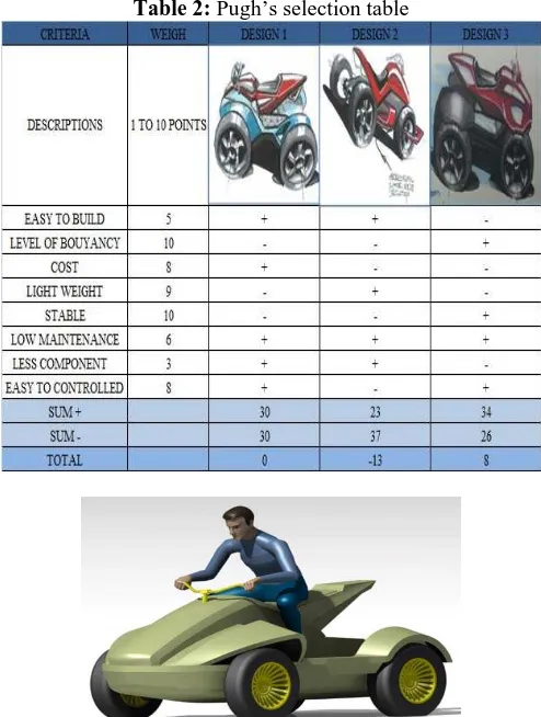
There are many ideas were produced but not reported as it actually the early step in designing process and several concepts are feasible to proceed to conceptual designs while the irrelevant ideas are eliminated. Once the conceptual design is finalized, the Pugh’s selection method is employed to conduct the analysis. The Pugh’s selection and assessment are evaluated by summation of ‘+’ and ‘-‘that indicate the element present in the criteria. The ‘+’ will be multiplied by weigh that been assessed for every criteria before been total up and the result is presented in Table 2 using Pugh method. There are eight criteria to be concerned to evaluate the best selection for the concept design.
Conceptual
Detail design geometry: CATIA
Analysis on The Design
Fabrication
Testing
Yes
No
International Journal of Science and Research (IJSR), India Online ISSN: 2319-7064
Volume 2 Issue 5, May 2013
www.ijsr.net
Easy to formed Level of buoyancy Cost
Light weight Stable
Low maintenance Less component Easy to controlled
The final design is shown in Figure 2. Next, after the conceptual design is finalized, the 3-dimension design is generated using CATIA V5 software. Figure 3 shows the 3D drawing of the amphibious vehicle body.
Table 1: Technical specification
UTeM
Amphibious Hybird Vehicle No.
1
Performance Engine size: 150cc Engine cooling system: ambient air
2
Dimension Overal length : 1400mm
Body Width : 1100mm Body height :1165 (from ground)
3 Payload
Up to 120 kg
4
Dry weight 350 kg
(exclude driver and safety equipment)
5
Drive layout Rear wheel drive
(RWD)
6 Water propulsion Seadoo water jet
7 Maintenance
Easy and quick
8
Target product cost
Low fabrication cost Low maintenance cost
Figure 2: Finalized Conceptual Design
Table 2: Pugh’s selection table
Figure 3: 3-Dimesional surface design of the vehicle body.
3.
Fabrication process
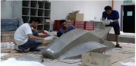
Fabrication process for the body of AHV is very crucial stage since all processes are executed manually and conventionally. Therefore, the most important aspect in fabrication process is to produce a good bodywork that meet the specifications and identical as possible to the design selected generate in CAD. The limitation in this process is to strictly follow the design specifications for the body of amphibious vehicle. The fabrication flow process for the body contains of several stages and it is shown in figure 4 below.
Figure 4: Fabrication process
Molding process is the most important stage where at this stage the quality of mold will influence the end product of the quality. A good quality of mold will quicker the time for
Demolding
Surface Finishing
Painting and Assembling Molding
Glass fiber layup
International Journal of Science and Research (IJSR), India Online ISSN: 2319-7064
Volume 2 Issue 5, May 2013
www.ijsr.net
surface finishing. The mold is made up from plywood which is use as a bone of the mold. Polystyrene is then applied to fill the empty space in the molding body. Wall filler will be used to fill pores of the molding surface and it will be sanding using sand paper to refine the surface finishing of mold. Figure 5 shows the plywood and polystyrene configuration and arrangement applied to the mold.
Figure 5: Molding process
As the mould is completed, the glass fiber which is from chop strand mat and woven fabrics are used to fabricate the body by using hand layup technique. Figure 6 show the process of hand layup techniques. A release agent, liquid of wax form will be applied onto the mold. This allowed the finished product to be removed cleanly from the mold without any sticking problem that will affect the finished product quality.
After the release agent have been applied to the entire surface mold, resin mixture which is consisting of polyester resin, epoxy type of resin is mixed together with its hardener and applied to the surface of the mold. Sheets of fiberglass cloth are cuts and lay onto the mold, and then more resin mixture is added using brush a brush or roller.
It is important to ensure that no air is trapped between the fiberglass clothed and mold and roller is used to remove the air pockets by pushing out the air pockets away from the fiberglass layer. Air pockets will cause fiberglass strength weaker. To add more layer of fiberglass, additional resin is applied and possibly sheets of fiberglass cloth also applied onto it. To make sure the resin is saturates evenly and air pockets are removed, hand pressure and roller are used. The work is executed quickly enough to complete the job before resin starts to cure, unless high temperature resins are used which will not cure until the part is warmed in an oven [5].
Figure 6: Hand layup technique
Next, demolding process is executed to separate the product and mold. Demolding process must be done carefully to avoid defects in the product. The next process is the surface finishing stage. Car body filler putty and sand paper is used to gain smooth and continuous surface finishing. The final finishing can be observed in Figure 7.
Figure 7: Surface finishing of the Bodywork
Lastly, the body undergoes painting process and it was assembled to the chassis by using bolt and nut. Marine sealer is applied to the area which is exposed openly and has gap between the surface to avoid leaking or water entering the body of the vehicle which can leads to additional weight problem to vehicle. The final product of the UTeM’s Amphibious Hybrid Vehicle is shown in Figure 8.
Figure 8: Shows the final bodywork for the UTeM’s AHV.
4.
Conclusion
The development of body for amphibious is carried out based on the technical specification information required. The process started from the design selection stage and completed with the fabrication process of the bodywork. The AHV composite bodywork produced using fiberglass suit the AHV capability to work on both the ground and water surface.
5.
Acknowledgement
This work is supported by the University Teknikal Malaysia Melaka (UTeM) through Short-Term Project PJP/2012/FKM (17C)/S01109 entitled “Development of Hybrid Amphibious Vehicle Propulsion System for Marine and Rescue Operation”. This financial support is gratefully acknowledged.
International Journal of Science and Research (IJSR), India Online ISSN: 2319-7064
Volume 2 Issue 5, May 2013
www.ijsr.net
References
[1] McBeath, S. and Rouke, Brian, “Competition Car Composites, A Practical Book”, Haynes Publishing, (2000).
[2] Savitsky D. and Brown P. W., “Procedures for hydrodynamic evaluation of planning hulls in smooth and rough water”, Marine Technology, Vol. 13, No. 4, October, pp.381-400, (1976).
[3] Neewey, C., and Weaver, G. (ed), “Materials Principles and Practice”, Butterworth Scientific, (1990).
[4] Multi Sport Composite, “A Practical Guide to Composites”, Multi Sport Composite Ltd, (1995). [5] Forbes Aird (1 April 1996) “Fiberglass & Composite
Materials: An Enthusiast's Guide to High Performance Non-Metallic Materials for Automotive Racing and Marine Use”, Penguin. pp. 86. Retrieved 12 June 2012.