PJP/2009/FKE (9C)/S00517
DESIGN AND DEVELOP WIRELESS BASED CONTROL OF INDUSTRIAL
ROBOTICS
SULAIMAN BIN SABIKAN
RESEARCH VOTE NO:
PJP/2009/FKE (9C)/S00517
FAKULTI KEJURUTERAAN ELEKTRIK (FKE)
UniversitiTeknikal Malaysia Melaka
2010
ABSTRACT
This project is about to design and develop wireless based control of industrial robot in an automated manufacturing plant with vision system. The plant works as the platform for electronic components insertion task using wireless based control of industrial robotic. CX-Designer programming is used to create a Graphical User Interface (GUI) to act as controller and monitoring system of the plant. CX-Programmer used to program the Programmable Logic Control (PLC) to control the plant and Machine Vision Software used to develop vision system. This project could help to reduce the requirement of manpower and at the same time increase the output production.
Key Researchers: Sulaiman bin Sabikan (Head)
Ahmad Zubir bin Jamil
Email: [email protected]
Tel. No.: 06 – 234 6548 Vot No.: PJP/2009/FKE (9C)/S00517
Contents
1 CHAPTER 1 INTRODUCTION ... 5
1.1 Overview ... 5
1.2 Background ... 5
1.3 Literature Review ... 6
1.3.1 A Remote Control Project to Enhance Undergraduate Students’ Interest and Knowledge in Industrial ... 6
1.3.2 Design Project for PLC Course: Automation Work Process Control ... 7
1.3.3 Design of Industrial Automated Systems Via Relay Ladder Logic Programming and Petri Nets 8 1.3.4 Integrated PLC Control With Wireless Camera Of AGV System [2] ... 9
1.3.5 Automated Production System For Object Transportation, Identification and Selection[3] ... 10
1.4 Problem Statement ... 11
1.5 Objectives ... 11
1.6 Project Scope ... 11
2 CHAPTER 2 PROJECT DEVELOPMENT ... 12
2.1 SOFTWARE DEVELOPMENT ... 12
2.1.1 PROGRAMMABLE LOGIC CONTROLLER (PLC) ... 12
2.1.2 CX-Designer 3.0 ... 19
2.1.3 HALCON Vision System Software ... 23
2.2 Hardware Development ... 28
2.2.1 Operation of Hardware ... 28
2.2.2 Wiring ... 30
2.3 System Integration and Troubleshooting ... 35
2.4 Final Report writing and Data Compilation ... 35
3 CHAPTER 3 RESULT ANALYSIS AND DISCUSSION ... 36
3.1 Programmable Logic Control (PLC) ... 36
3.2 CX-Designer ... 37
3.2.1 Plant Page ... 38
3.2.2 Event page ... 39
3.3 HALCON Vision System... 40
3.4 Plant (Hardware) ... 42
4 CHAPTER 4 CONCLUSION, SUGGESTION AND RECOMMENDATION ... 48
4.1 Conclusion ... 48
4.2 Recommendation ... 48
5 REFERENCE ... 49
1
CHAPTER 1 INTRODUCTION
1.1 Overview
This project is about to design and develop wireless based control of industrial robot in an automated manufacturing plant with vision system. The plant works as the platform for simple electronic components insertion task using wireless based control of industrial robotic. CX-Designer programming is used to create a Graphical User Interface (GUI) to act as controller and monitoring system of the plant.CX-Programmer used to program the Programmable Logic Control (PLC) to control the plant and Machine Vision Software used to develop vision system. This project could help to reduce the requirement of manpower and at the same time increase the output production.
1.2 Background
The Robotic Industries Association defines the industrial robot as: "A reprogrammable, multi-functional machine designed to manipulate material, parts, tools or specialized devices through variable programmed motions for the performance of a variety of tasks." Robots are capable of performing a wide variety of tasks, such as: material handling, spot welding, arc welding, assembly, dispensing, material removal, coating and inspection. Robots are used in many industries including: automotive, semiconductor, electronics, aerospace, food and beverage, pharmaceutical, consumer goods, plastics, construction and medical devices. They are used in industrialized countries worldwide, especially in the United States, Japan, Germany, England, France, Singapore, Korea, Canada, Taiwan and Mexico.
1.3 Literature Review
1.3.1 A Remote Control Project to Enhance Undergraduate Students’ Interest and Knowledge in Industrial
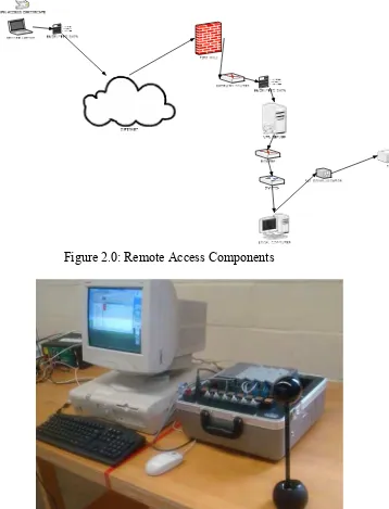
The project includes constructing and controlling a system remotely. The system operates by loading parts onto a conveyor belt which then transports parts to a labelling station.
The station uses a photoelectric sensor todetect the part, a pneumatic actuator to manipulate the part, and a labelling mechanism to label the part. The process is controlled by programming running on an Allen Bradley PLC. When the photoelectric sensor detects the arrival of the part, the PLC program stops the conveyor and uses a time delay to allow labelling to take place. The actuator then moves the labelled part into a storage area and the process is repeated.
Figure 2.0: Remote Access Components
Figure 2.1: PLC Remotely Accessed System
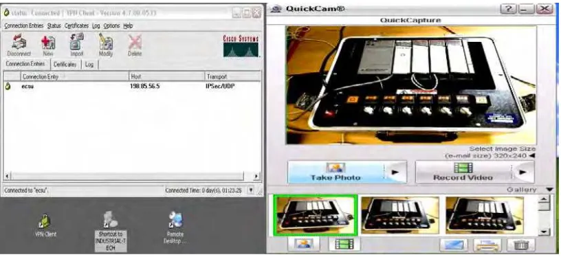
For example, the remote user uses a client (remote) computer to log into the host computer from a remote location over the Internet, and has access to RSLogix 500 software installed on the host computer andessentially downloads the programto a PLC unitlocated in the host location. Figure 2.1 shows the login and the view of the PLC unit through the web camera on the remote computer.
Figure 2.2: Login and Web Camera Viewof PLC Unit
1.3.2 Design Project for PLC Course: Automation Work Process Control
This project is about setting an automation work process control. Therefore, the idea of an assembly line was chosen as a good application of a PLC programwith timers and counters. The next stage was to design the automation work process that the PLC would be used to control. The project simulated aparts handling operation using a conveyor belt that would carry parts past a proximity sensor. A robot would be used for part handling.
When the given amount of parts pass the sensor, the robot would be set into motion, grab the tray into which the part is accumulated,and move themto a final packaging area.
The last step in the design process was to develop the actual ladder logic diagram for the PLC program. This programwas implemented using the Siemens S7-214 PLC. The S7-200series is a line of integrated PLCs that can be used in various automation applications. The program was downloaded, tested, and debugged to ensure that it worked properly.
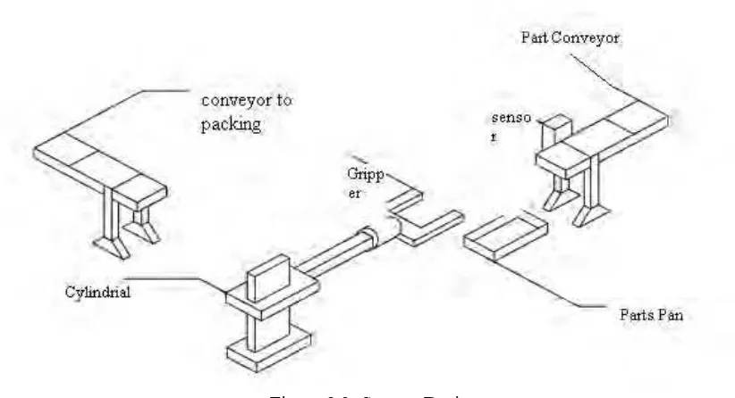
Figure 2.3: System Design
The next step in the project design process was to design the automation work process that the PLC would be used to control. A robot was something that would be a must for part handling. Also, a conveyor belt would be a good addition. The author decided to go with a parts handling operation with the implementation of sensors. A conveyor belt would carry parts past a proximity sensor. When a given amount of parts pass the sensor, the robot will be set into motion, grab the tray into which the parts have accumulated, and move them to a finished area for packaging. While this process is finishing, the next set of parts has accumulated in a tray at the end of the conveyor (the tray will be replaced each time by an operator) and the robot again goes to pick up the accumulated parts. For this project, the process will be resent after the second accumulation of parts for simplicity. In this stage of the design process, a design drawing was created using Mechanical Desktop. The design drawing is shown in Figure 2.4.
1.3.3 Design of Industrial Automated Systems Via Relay Ladder Logic Programming and Petri Nets
Programmable logic controllers (PLC’s) using relay ladder logic (RLL) programming have been the workhorse for controlling event-driven industrial automated systems. RLL proved flexible compared to the hardwired RLLcontrol implementation, due to its feature of software implementation. As automated systems become more complex, they also become more difficult to understand and maintain. It takes tremendous effort to accommodate specification changes, which become frequent, to meet today’s flexible and agile automation needs. Several methods emerge to overcome the short comings of RLL. Petri nets (PN’s), initially proposed as a modelling tool, have been developed as such a method. This paper adopts an industrial scale system to compare RLL and PN design methods so that the advantages of PN-like approaches are fully recognized. The criteria are the understand ability that relates to the ability to evaluate the programmed logic, to verify its correctness, and to maintain the control system as well as the flexibility that relates to the easy modification of logic when the specification changes. To the authors’ knowledge, this is the first work that takes an existing industrial system, conducts discrete event control designs by using both RLL programming and PN methods, and performs a comparative study on them. Together with the previous comparison results through small-scale systems, the results of this study support that PN-like advanced discrete event control design methods are better than RLL, in terms of the understand ability and flexibility of a resulting control design.
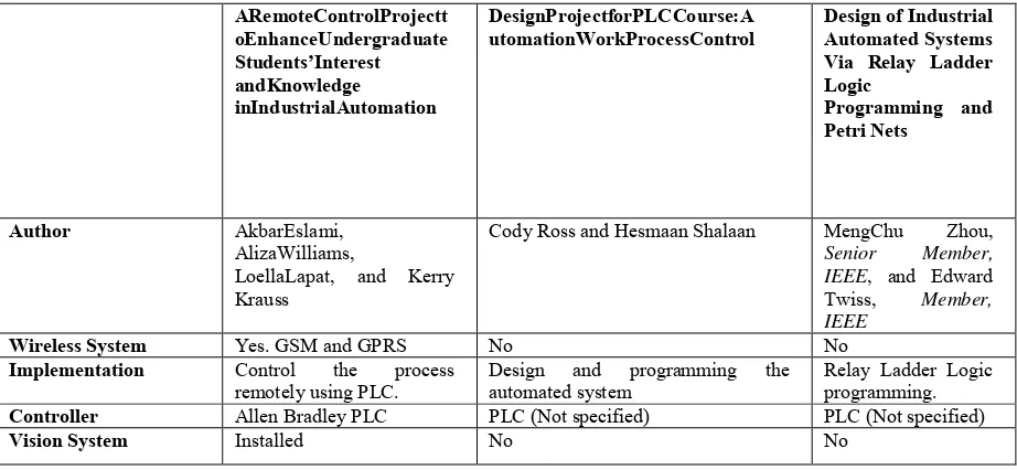
Figure 2.4: The Review of RRL System The table below shows a summarization of the 3 journals:
ARemoteControlProjectt
utomationWorkProcessControl Design of Industrial Automated Systems Via Relay Ladder
LoellaLapat, and Kerry Krauss
Cody Ross and Hesmaan Shalaan MengChu Zhou, Senior Member, IEEE, and Edward Twiss, Member, IEEE
Wireless System Yes. GSM and GPRS No No
Implementation Control the process
remotely using PLC. Design and programming the automated system Relay Ladder Logic programming.
Controller Allen Bradley PLC PLC (Not specified) PLC (Not specified)
Vision System Installed No No
Table 1: Summarization of journals
1.3.4 Integrated PLC Control With Wireless Camera Of AGV System [2]
The AGV vehicle is first developed in 2005 at King Mongkut’s Institute of Technology North Bangkok. Thevehicle was controlled by an inboard PLC control. The design of the vehicle consists of 3 wheels. The front wheel isused for steering and driving, whereas the 2 rear wheels are free and equipped with 2 encoders. The controlled strategyis based on two main purposes: the path is stored in the PLC memory and the vehicle displacement is calculated by thewheel rotational measurement. The comparison between the required path and the actual position of the AGV allowcalculating deviation error. Function of error, a correction of strategy of driving of driving speed and steering angle, isapplied in order to get a smooth and precise displacement. However, the past developed vehicle is lack of remotecontrol. This paper presents the integrated PLC inboard control with wireless camera. The integrated control schemecan apply to controlling the vehicle from the control room or remote areas. The distance of camera control 50-100meters. This control can improve more efficient of the AGV vehicle system.
Figure2.5: IntegratedCameratoAGV:a).WirelessCameraInstallation,andb). AV-receiverModuleinRemoteSiteof Operation.
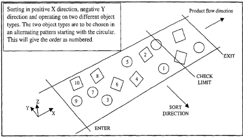
1.3.5 Automated Production System For Object Transportation, Identification and Selection[3]
System for selection and transport of an object out of plurality of objects in operation area comprising a system for detection of objects presence in operation area and an industrial robot including a manipulator and an operating system having a computer memory for storing information about the objects presence in operation area.
Figure 2.7: Overview of Operation System
1.4 Problem Statement
The problem statements for this project are:
i. Most of the industrial robots are controlled with wired remote control which makes the movement range limited due to the cables.
ii. The output produced using manpower is quite low because of the limitation of work time. iii. Most industry risk human life to attain certain process.
iv. Human being cannot meet 100 % efficiency all the time.
1.5 Objectives
The objectives of the project are:
i. Investigating the implementation of wireless based control of industrial robot. ii. Reduce the amount of hard wiring used by controlling the robot wirelessly. iii. Applying robot in conditional working space.
iv. Increase the robot’s movement range.
1.6 Project Scope
The scopes of this project are:
i. Design and development of working station (software and hardware).
ii. Development of Graphical User Interface (GUI) for working station controlled by PLC .(software)
iii. Development of simple image processing for vision system. (software)
2
CHAPTER 2 PROJECT DEVELOPMENT
This project will be concentrating in electronic component insertion task onto a PCB board. This task uses conveyor to move the PCB boards from the loading area to the unloading area. PLC is chosen as the controller for the conveyor system because it gives more structured approach rather than conventional way. The ability of the automated system is to perform work automatically with minimum or without human supervision or intervention.
The working principle of the project is the PCB board is placed onto the conveyor by Robot 1 in Loading Station. Then, the conveyor moves the PCB board to Assembly Station where Robot 2 inserts the electronic component 1 and electronic component 2 onto the PCB board.Robot 1 move from HOME to AWAY position during this process. Then, the conveyor transports the PCB board to the vision station where the vision system examines whether the components are well inserted and give results PASS/FAIL. If the component is well inserted (PASS), it will be sent to the good bin while if there is any mistakes in the insertion (FAIL), the PCB board will be sent to the defect bin. Once the inspection finishes, conveyor transport the PCB board to the unloading station where it is picked up by Robot 1 and placed in either good bin or defect bin. Robot 1 move back to from AWAY to HOME position after that.
2.1 SOFTWARE DEVELOPMENT
Software Development is done in two separate stages. The first stage is about software familiarization and the second stage is software development. In this software familiarization, there is the way to find out suitable software for plan control and supervisory. This stage is done by choosing three different purposes. For the first software, it is used to create graphical user interface, GUI for the plant. The second software used to develop a programming language for entire plant. The third software is used to create a supervisory system in low vision station. The development of all three software conducted after familiarization process end.
2.1.1 PROGRAMMABLE LOGIC CONTROLLER (PLC)
The application of the software and how to design and develop the command program is discussed in this section. The software that be used is Programmer version 8.0 for simulation purpose and CX-Programmer version 1.0 for CP1E-OMRON PLCreal time application.
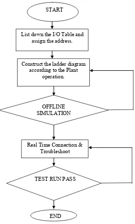
Flowchart
Yes
Figure 3.11: Flow Chart for the PLC ladder diagram design process using CX-Programmer
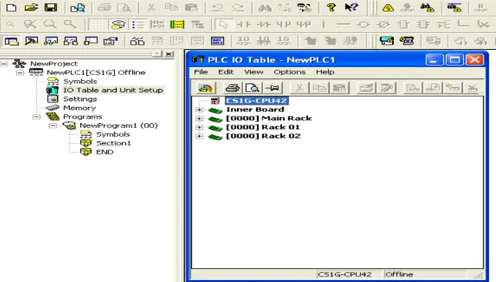
Create for a new project
Click a button for new project creation of CX-Programmer START
List down the I/O Table and assign the address.
Construct the ladder diagram according to the Plant
operation.
OFFLINE
SIMULATION
TEST RUN PASS Real Time Connection &
Troubleshoot
END
Figure 3.12: Create New PLC Project.
The dedicated support software for each unit can be started prior to communication setting of CX-Programmer. It is not necessary to communication using the dedicated support software if set up communication has been done over here. Network type USB chosen instead Toolbus because this CP1E cannot undergo simulation mode.
Creating Unit Configuration
Start the I/O Table/unit setup function.
Figure 3.13: Create Unit Configuration
Ladder Diagram and Mnemonics code.
For Part 1 (Loading Station and Conveyor)
In this section, the ladder diagram design to fulfill loading station requirements including the conveyor operation. Conveyor home position, robot 1 home position and PCB loading complete are used as condition to on the conveyor in this part. Set coil used as holding circuit and reset system.
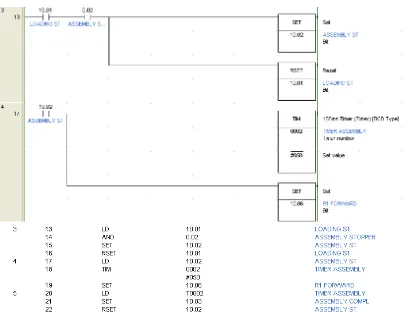
Figure 3.14: Ladder Diagram and Mnemonic Code Part 1 (refer to Appendix B) For Part 2 (Assembly Station and Robot 1 Forward)
In this part, the conveyor stop by assembly stopper (sensor), followed by robot 2 completed the assembly task, and robot 1 moves forward to away position. Timer 2 and set coil used to stop and start the conveyor respectively.
Figure 3.15: Ladder Diagram and Mnemonic Code Part 2 (refer to Appendix B)
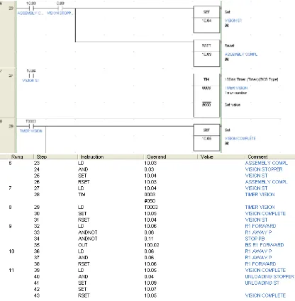
For Part 3 (Vision Station)
In this part, vision stopper (sensor) will stop the conveyor and activated the timer to allow the stand alone Vision System process to be completed in 20 seconds. After given period, the timer will turn ‘ON’ the set coil 3 to activate the conveyor back.
Figure 3.16: Ladder Diagram and Mnemonic Code Part 3 (refer to Appendix B)
For Part 4 (Unloading Station)
In this part, conveyor will be stopped by unloading stopper (sensor). Timer 4 and timer 5 will be activated and Robot 1 will pick the PCB from conveyor and placed the PCB to the PASS/FAIL bin. After given period, timer 4 activated the conveyor move to home position and timer 5 activated Robot 1 track motor turn reverse to homo position. One cycle completed.
Figure 3.17:Ladder Diagram and Mnemonic Code Part 4 (refer to Appendix B)
For the part 5 (Stepper motor)
For the stepper motor, it must be use the specified program and data memory. Command type DIFU used to give signal to the motor. This program divide into 3 parts, part1 for Robot 1 forward (motor 1), part 2 for Robot 1 reverse (motor 1) and part 3 for conveyor forward (motor 2). All the settings can be set directly at the ladder diagram or in data memory.
(a) Motor 1 (Robot 1) Forward
(b)Motor 1 (Robot 1) Reverse
(c)Motor 2 (Conveyor) Forward
Figure 3.18: Ladder diagram for Part 5 (refer Appendix B)
2.1.2 CX-Designer 3.0
This GUI is developed by using CX-Designer 3.0 that shows in figure 3.10. The purpose of this GUI is built is to monitor and control the plant. This GUI is required to communicate with hardware (plant). For simulation purpose this GUI can be run using ladder diagram and for real time usage, CX-Designer 3.0 required to be connected with human machine interface, HMI and programmable logic control, PLC to start RUN the GUI. There are 5 screens used to control the plant excluding the two robots. The screen for this plant is:
(i) Screen 000 – Main Page (ii) Screen 001 – Plant Page
(iii) Screen 002 – Control Panel Page (iv) Screen 003 – Alarm Page
Flow Chart
NO
YES
Figure 3.19: Flow Chart for the GUI design process using CX-Designer Procedure in Developing GUI
To create a new GUI, choose the model of the CX-Designer. In this project, choose file, click new and choose NS5-SQ0[]-V2 model and the system version 6.2. Then, create the file name.
Figure 3.20 Start up GUI Design Then select the number and the title for the first screen.
Figure 3.21: Screen Page setting
To create a push button, select a push button menu then set as the following. In the example below, how to create the start button is described.
Setting:
Action Type Momentary
Write Address 0000.12 (PLC Address)
Color Of Shape ON=Green ; OFF=Red
Label ON
Frame 3D Frame & Border
Figure 3.22: Display for the input (Push Button)
For the next push button stop as “STOP”, “NEXT”, “PREVIOUS”, and “ALARM”, repeat the step as previously done.
To create conveyors in GUI, choose the bit lamp then click at the ‘Select Shape’. Setting:
Shape Type Conveyor
Display Address SERIALA:10000.00
Colour/ Shape ON = GREEN ; OFF = GREY
Label CONVEYOR
Control Flag Display
Figure 3.23: Display for Output (Conveyor)
Repeat this step to create the motor, robot track, robots and other outputs as per requirement.
Figure 3.24: Display for component input and output.
To create alarm display and alarm event/history, open the new screen. Select the alarm/event display at the functional object menu.
Setting:
Date & Time Format Display Date; Time
Display Type High Alarm, Middle Alarm, Low Alarm Event
Frame 3D Frame
For the alarm history, click Alarm/Event Summary/History button at the functional object menu.
Setting:
Display Data Alarm History
Default Display Order From New Date & Time
To make the alarm event, the data of the event must be registered to the Alarm Event section. In this section, all the data of event will be save in the specified address. For example;
Setting:
Message ‘Robot Track Warning’
Address SERIALA: 00000.01
Detection Type Raise Alarm on Set (to 1) of Address
Display Type High Alarm
Save To History Yes
At the end of the design process, the completed design of the GUI has been developed successfully following the specified requirement.
Figure 3.25: Display the complete GUI
2.1.3 HALCON Vision System Software
HALCON is the most comprehensive software for machine vision and also can be applied low vision system application. This software also has its flexible architectures for rapid development of image analysis and machine application. The program for vision system developed using HALCON own language.
Flowchart
Figure 3.26: Flowchart of Vision System Design Process using HALCON
Procedure in Developing HALCON
First select all program followed by MVTec HALCON 7.0 and HDevelop selection to open the software.
START
Close all frame grabbers. Grab image from Web-Camera following setup at
Vision Station.
Load image to graphic window. Gray the image. Shade the image part with mean gray rating from “20-145” value
with red color.
Select the region in the range of “6000-1000”value. Fill the regions with green color. Defined the selected regions as “SRegion”.