Doctoral Dissertation
Fatigue Fracture Properties of Nanoclay and Wood Plastic Composites
September, 2015
MOHD NUR AZMI BIN NORDIN
Table of Contents
1.1.2 Wood-Plastic Composites (WPCs) 1.2 Objectives and outlines
Chapter 2 Electron Probe Microanalyzer Evaluation of Fatigue Fracture Surface of Nanoclay-Epoxy Composite Materials.
2.1 Introduction
2.2 Experimental methods 2.2.1 Materials
2.2.2 Specimen fabrication 2.2.3 Tensile and fatigue tests 2.2.4 Elemental observation 2.3 Experimental results
2.3.1 Tensile and fatigue properties 2.3.2 EPMA observation
2.4 Discussion
2.4.1 Agglomerate evaluation by image analysis 2.4.2 Evaluation using the nearest neighbor functions 2.5 Conclusions
3.2.2 Specimen fabrication 3.2.2.1 Process A
3.2.2.2 Process B
3.2.3 Tensile and fatigue tests 3.2.4 Fracture surface observation 3.3 Results and discussion
3.3.1 Tensile properties 3.3.2 Fatigue properties 3.3.3 Surface observation 3.4 Conclusions
Chapter 4 Evaluation of Fatigue Fracture Surface of Wood Filled Polypropylene Composites
4.1 Introduction
4.2 Experimental methods 4.2.1 Materials
4.2.2 Specimen fabrication 4.2.3 Tensile and fatigue tests 4.2.4 Fracture surface observation
Nomenclature
CMCs Ceramic matrix composites MMCs Metal matrix composites PMCs Polymer matrix composites FRP Fiber reinforced plastic
UD Unidirectional
XRD X-ray diffraction
TEM Transmission electron micrographic WAXD Wide angle X-ray diffraction SEM Scanning electron microscopy EPMA Electron probe micro-analyzer WPCs Wood-plastic composites
PP Polypropylene
NE- Nanoclay-epoxy
MAPP Maleic anhydride polypropylene
S-N Stress to the number of cycles to fracture MDF Medium density fiberboard
MA Maleic anhydride
AA Acrylic acid
Symbols and Units
Fci Fatigue fracture surface at crack initiation area
Fpi Fatigue fracture surface at peak intensity area
G(R) nearest neighbor function
R radius from nanoclay agglomerate's centroid di nearest neighbor distance
rpm rotation per minute
phr part(s) per hundred parts of resin wt.% percentage of weight (mass) fraction
°C degree Celsius
Chapter I General Introduction
1.1 Background
Development of new advanced materials due the needs from the industries has placed a
number of conditions such as light in weight, high durability and low production cost as a
minimum prerequisite that are necessary to be full filled. The production of composite materials
for example has put these elements as a main goal that is by combining two or more materials
with different properties in order to give a performance in service which is superior to the
properties of the individual materials. The composite materials have been used over centuries as
construction materials - ancient Egyptians mixed the wheat straws with the Nil's mud to make
bricks for their house, where the straws functioned as reinforcement to the mud to make the
bricks strong, besides keep the house cool when it is hot in summer and vice versa. The
implementation of the 'combining materials' idea bring interest to many people from various
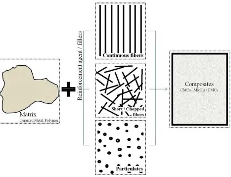
fields over the time until recent, which is known as a composite materials in the present-day. Fig.
1.1 illustrates the schematic of reinforcing and binding elements of composite materials. It is
commonly use in many applications such as aerospace industry, where the high thermal shock
resistance and excellent fracture toughness of ceramic matrix composites (CMCs) material is
applied for heat shield of the space vehicles, and also widely applied in automotives and as a
material for sports equipments due to its light weight, tremendous elasticity and strength. Metal
matrix composites (MMCs) are practically used for vehicle parts such as engine, rotors and disc
brakes; because of relatively high thermal properties of the composite materials, and also
commonly applied as a structure frames for many sports applications such as bicycles, rackets
Fig. 1.1 Schematic of composites elements.
Composite materials are designed to suit its properties to a certain application in order to
optimize the consumption of the raw materials while giving a maximum performance. Similar to
the other types of composites stated above, polymer matrix composites (PMCs) is applied to a
certain parts of products in which appropriate with its range of properties and performances such
as the interior and exterior parts of the vehicles, containers and also as a building panels. Over
decades, numerous studies on PMCs properties as well as the development of new type of PMCs
had been carried out. Fiber reinforced plastic (FRP) composites, for instance, gain interest from
both manufacturers and researcher on improving the bulk properties of the materials to maximize
higher modulus per unit weight, specific modulus and strength per unit weight, specific strength
when compared to other metal or monolithic materials, i.e., imply the weight savings over the
whole structure, thus resulted in greater efficiency and energy savings to the outcome of the
composites products. Plastic is defined as a polymeric material that formed by large molecules
that are composed of many (poly-) repeats of simpler structural unit, the mer, connected by
covalent chemical bonds. There are two types of polymeric plastic regarding to the engineering
materials definition; thermosets and thermoplastics [1]. Thermosets are low-molecular-weight
polymer that formed a cross-linked structure from the chemical reactions driven by the heating
that is generated either by the reactions or from the external supplied heat. In opposites,
thermoplastics are high-molecular-weight polymer that held together by weak secondary bonding.
The cross-linking reaction does not formed in the thermoplastics as thermosets does, however,
they can be reprocessed. The weak secondary bonds break down when high temperature is
applied and reform during the cooling process. The differences between thermosets and
thermoplastics were summarized as shown in Table 1.1. It is known that the virgin plastic or the
pure polymeric materials have low in strength and stiffness properties; moreover, most are less
resistance towards high temperature, which make it difficult to be applied individually in many
engineering applications. Making the polymeric plastic as the binding constituent of composite
materials, thus, by incorporating the fillers like fibers or particulates into the matrix, the
mechanical and thermal properties of the plastic materials indicated an excellent improvements
[2-5,20] despites several difficulties such as poor distribution and lack in interfacial adhesion
between the fillers and the matrix, that need to be encountered. In this study, the PMCs were
where the performances of these different PMCs material were measured and evaluated through
their reliability from the mechanical behavior.
The reinforcement agent or fillers in composite materials plays an important role in order to hold
the matrix that is by transferring the load and act as a crack-bridge at a crack tip upon failure. Fig.
1.2 indicates several examples of reinforcements that are commonly used for composite
materials. The compatibility of fillers with the matrices has put extra advantageous for
composites to uphold the local area towards given loads and therefore enhanced the performance
of the overall composite materials. There are several types of fillers depends on the (i) structure
or geometrical shapes, (ii) size and (iii) origin of the fillers.
i. Structure or geometrical shapes - Unidirectional (UD) fiber is commonly used
as reinforcement agent in many composite materials. It may be includes under the
continuous fiber type that provides strong strengthening result to the matrix, and
may stacked together of different layers and directions to form a laminae structure.
The laminae structure also may consist of woven roving of continuous fiber or a Table 1.1 General characteristics of thermosets and thermoplastics. Source:[1]
Thermoplastics Thermosets
high molecular weight and high viscosity low molecular weight and low viscosity monomers
do not form cross-linking reactions cross-linked structures are generated from the chemical reactions that are driven by heat
able to reprocessed cannot be re-melted
mix of aligned unidirectional layer with random short fibers including chopped
fibers or whiskers. High stiffness of particulates fillers of various geometrical
shapes such as spheres, plates, ellipsoids or hollow, are often used as fillers to
obtain a micro- or nano-size effect which offers an excellent improvements of
composites properties.
ii. Size - The order of the size of fillers that is from nano- to micron-size, gives
variety in results on the performance of the composite materials. The
improvement of the composite materials properties can be achieved by the
addition of low amounts of well dispersed small size fillers, in which a higher
interfacial surface area results from an increased aspect ratio or surface–volume
ratio of the fillers. Therefore, for example, the required amount of nano-size
fillers is much lower than that of conventional micro-order fillers, such as ceramic
particles and short fibers, in order to maximize the properties of the composites
which also bring along the economic benefits.
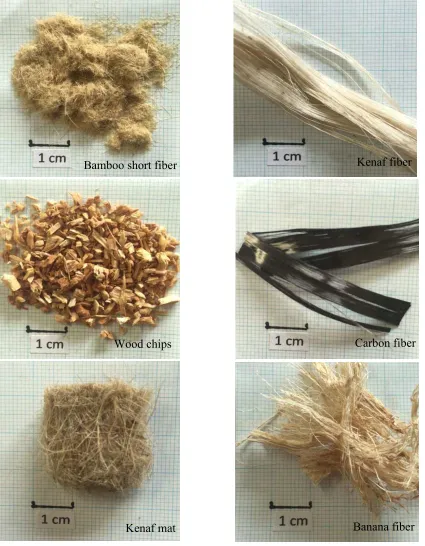
iii. Origin - Generally, fillers can be differentiate from its material such as the glass,
carbon, boron fibers or the fibers that originated from the plants or animal, which
is namely as the natural-based fibers. The use of natural-based fibers had been
practically used in PMCs type composites over years and increasingly due to the
awareness of the environmental problems. Commonly, the waste from the forestry
or agriculture were processed as a fillers of PMCs which bring lessen to the used
Fig. 1.2 Different types of reinforcements applicable to fabricate composite materials.
Bamboo short fiber Kenaf fiber
Wood chips Carbon fiber
1.1.1 Polymer nanocomposites
Polymer nanocomposite is a combination of nano-size stiff fillers with the polymer
plastic matrix. The nano-size fillers can be defined as the particle that has at least one dimension
in nanometer scale. The incorporation of nano-size fillers into plastic polymer or rubber creates a
new class of material with an outstanding performance in functional properties such as gas
barrier, as well as mechanical and thermal ones [3-5]. From the end of the last century,
nanocomposite materials have been attracting a great attention to industrial sectors and academic
researchers, who focus on the broad possibility of nano-size fillers compared to micro-size ones.
As mentioned above, there is an economical point such that the required amount of nano-size
fillers is lower than the conventional micro-order fillers, i.e. ceramic particles, short fibers, and
many more. Moreover, great attentions to the nano-size fillers emerged for several other reasons
including [6, 7]:
i. The fillers usually have different properties from bulk properties of the same
materials;
ii. The fillers are small defect compared to micro-size fillers which are similar in
size to the critical crack size, and this will cause a premature crack;
iii. Due to larger surface area of fillers, nanocomposites have a large volume of
interfacial matrix material with properties.
However, insufficient dispersion of nano-size fillers in polymeric matrices brings less
mechanical properties [4, 8] because of the fillers often form micron-size agglomerates. The
portion that is containing more agglomerated fillers tends to impart higher stress concentration
on polymeric matrix than the other parts. This reaction leads to a crack formation and thus
factors that contribute to the insufficient dispersion that affect the properties of the
nanocomposites, such as the synthesis methods during the fabrication process, the types of
nano-particles that been used and also the characteristics of polymer matrix, where it is compatible or
not with the compounded fillers.
The dispersion of fillers in polymer commonly tends to become partially exfoliated and
intercalated clusters, where the fillers are homogeneously distributed. The distribution states
have been verified through an X-ray Diffraction (XRD) method analysis or with high resolution
observation by using transmission electron micrographic (TEM) [5, 9]. As concern by many in
this field, however, it is almost difficult to achieve a fully exfoliated state only by a single
physical process. We need to take into account the other factors such as chemical modification of
nano-size particles that might influence appropriate formation for the internal microstructure of
the polymer nanocomposites. Evaluation on dispersion order of nanoclay particles commonly has
been done through a qualitative analysis of which the nanocomposites’ structure can simply be
done using a wide angle X-ray diffraction (WAXD) analysis, scanning electron microscopy
1.1.2 Wood-Plastic Composites (WPCs)
Current issues on composite materials have been discussed and published in many
literatures, including some virtuous inventions on improvement of mechanical properties and
hybridizing conventional composites with bio-based fillers. This work includes the development
of woods as reinforcing fillers for polymeric matrix to form an environmentally friendly
composite material. Wood materials have been used in many products such as household articles,
furniture and other interior items. The combination of wood flour with polymeric matrices, so-
called as wood-polymer composites (WPCs), brings a new sight in wood-based application, i.e.
high durability and excellent mechanical properties such as high tensile strength and stiffness
[10-12] and low density. As fillers, these natural particles play a role of transferring the load and
act as a crack-bridge at a crack tip upon failure. However due to the incompatibility of wood
surface structure with the polymer matrix, the maximum performances of compounded wood
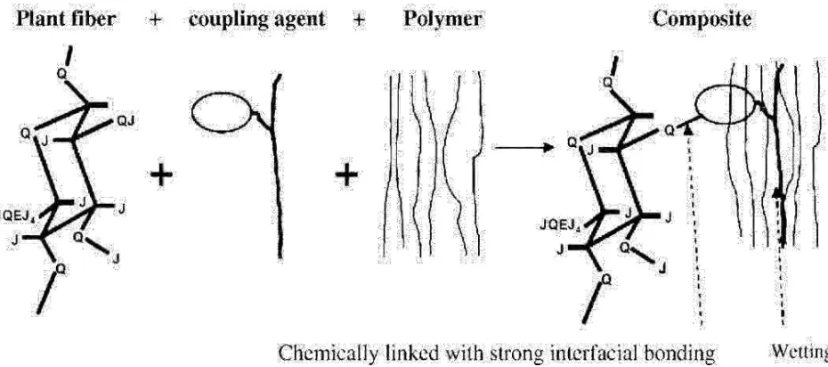
particles in the composite materials are difficult to achieve. Fig. 1.3 illustrates the role of
Fig. 1.3 Schematic figure of the mechanism of coupling agent between hydrophilic fiber and
coupling agent / compatibilizer in WPCs material. Moreover, the characteristics of wood flour
are different with respect to the type of trees and harvesting time and it is easily influenced by
the presence of moisture.
Another factor that contributes to the performance of WPCs material is the distribution of
wood flour, i.e. the optimal amount of wood flour creates an appropriate condition for the fillers
to transfer the loads and avoids the formation of wood cluster due to the lack of mixing process
during the fabrication of WPCs. A study by Leu et al. [14] offers an idea of the optimization of
wood fillers and other material composition in WPCs that helps to achieve ideal properties of the
material. It is stated that by compounding up to 50 wt.% with the maximum value of coupling
agent, maleic anhydride polypropylene (MAPP) at 3 wt.% able to enhanced the mechanical
properties of WPCs. However, less data can be achieved regarding to the fatigue properties of
the WPCs materials, which is highly recommended to be clarified. This is because the fatigue
behaviors of WPCs material are important to estimate the life span or durability of the WPCs
since the material itself has large potential to be applied in many applications. For an example,
according to the fatigue behavior of natural fiber, Dijan et al. [15] suggested that high loading
frequency reduced fatigue life of coir fiber reinforced polypropylene composites due to higher
heat generation and less time available to dissipate the heat. This study imply the effect of heat
that generated from loading and unloading actions, which is considerably close to the real
applications, i.e. different loading frequency take place will results in heating and softening
effects of the polymeric resin. Here, by understanding the fatigue behavior of WPCs material
helps to contribute to a safer and reliable structure design for various applications in the future.
The failure behavior of green composites has recently gains a great attention, especially
which is relatively difficult to control, and thus, need a particular methods and solution to
overcome the difficulties. Also, the environmental factors such as the vibrations and the
weathering effects may become an important point that causes a catastrophic failure of the
bio-composite materials. These factors are more likely to be related with improper analysis of
dynamic loading frequency or inappropriate fiber composition and its compounding behavior.
Therefore, the fatigue test - a method for determining the behavior of materials under fluctuating
loads - revealed a significant indication on the durability of materials, which is needed to
estimate the life span of the material used. The fatigue process of a material is thought to begin at
an internal or surface flaw, and the failure effect accumulates after several repetitive loads
actions that may caused stress concentration at a point of cumulated damage, that is called as an
initial crack point. Then, it generates a shear flow along the slip planes that resembles a crack,
and propagates along the weak regions before caused a catastrophic failure. The fatigue study on
new materials has become a must in order to design a strong and safety structure with high
durability characteristic. A study by Shao Xiong et al. [16] on the properties of flax-epoxy
layered composites under fatigue loading underlined the importance of interfacial adhesion
between the natural based fillers and hydrophobic resin for the enhancement of the performance
of the composites material. Larger number of fiber pulls out and fiber prints indicate the poor
adhesion between the flax fibers and epoxy matrix. The interfacial adhesion of green composites
had been studied literally; since the combination of these two constituents without the use of an
appropriate compitibilizer or coupling agents is commonly lessen the properties of the materials
[17]. Indeed, the enlargement of natural based fibers as a potential reinforcement agent in
composite material leads to interesting findings, nevertheless, undiscovered factors and
1.2 Objectives and outlines
This study aim to understand the fatigue failure mechanism of particulates filled polymer
based composite materials and to clarify the fatigue fracture behavior from the fracture surface
observation. For these purposes, two types of composite materials; nanoclay nanocomposites and
wood-polymer composites (WPCs) were fabricated and tested. The tensile and fatigue tests were
carried out for each type specimen - significant means to clarify the reliability of the materials
and to understand the failure mechanism. As for the matrices, epoxy and polypropylene (PP)
were used as a binder constituent for nanoclay nanocomposites and WPCs, respectively. The
compounding of wood fibers and nanoclay fillers into the polymer matrix brings a structural
change that caused by the presence of the micro-structure of the fillers itself or as a result from
the clustering of the fillers that is incompatible with the polymer. Here, the distribution of the
fillers and the compatibility of natural-based fillers with the hydrophobic polymer matrix were
taken as the major subject in this study, i.e. by clarifying the relation between the mechanical
properties with these factors, it is expected to fulfill the aims of this study.
In Chapter II, the neat epoxy matrix and nanoclay-epoxy (NE-) composites specimens
were prepared with different nanoclay amount to investigate the influence of the nano-size fillers
amount to the tensile and fatigue properties. The distribution of nanoclay particles was discussed
and evaluated through an analysis conducted at the fatigue fracture surface and at the arbitrary
cross-sectional area. It is assumed that the cross-sectional area contains a moderate distribution
level that result in the lower stress concentration at as compared with at the fracture surface. The
electron probe microanalyzer (EPMA) machine was used to conduct an elemental study on both
fracture and cross-sectional surface, and a qualitative analysis was performed from the
agglomeration and clustering state, play an important part in determining the failure factors of
this material despite lessen the properties of NE composite materials.
In Chapter III, different coupling agent MAPP amount of WPCs specimens was
fabricated in order to investigate the effect of coupling agent on fatigue properties of WPCs. The
tensile and fatigue test were carried out for each type of specimen. The obtained mechanical
properties were discussed regarding to the different effects of coupling agent amount in the
composites that expected to improve interfacial adhesion between wood fibers and PP matrix.
The cross-sectional area and the fracture surface were characterized by the SEM and 3D laser
microscope, respectively.
In Chapter IV, WPCs specimens with different weight fraction of wood fibers were
prepared and the tensile and fatigue tests were carried out for each type specimen. The influence
of wood fibers on fatigue properties was clarified and the fatigue fracture behavior was
characterized from the image analysis. Moreover, further discussion on the fracture damage
mechanism of WPCs will be carried out in this chapter.
Chapter II
Electron Probe-Microanalyzer Evaluation of Fatigue Fracture
Surface of Nanoclay–Epoxy Composite Materials
2.1 Introduction
Among the wide possibilities presented by various materials, polymer-based
nanocomposites have been used in many applications, particularly in the automotive and
packaging industries, because of their rigidity, light weight, and high endurance properties.
These materials are anticipated for wider use for other applications. Meanwhile, the
incorporation of nano-size fillers such as clay particles into polymer matrix materials of fiber
reinforced plastic (FRP) composites has been studied [9, 18]. This study assesses the importance
of toughening the matrix material for additional applications of composite materials. To date,
many studies have examined the preparation, testing, modeling, and analyses of nanoclay-filled
polymer-based composites [19].
Nanoclay is known as an ideal nano filler to improve virgin polymer because of its high
aspect ratio, low cost, and ease of availability [20]. Nanoclays are classified into three types
based on the condensation ratio of silica to an alumina sheet, such as two-sheet minerals
(dimorphic), three-sheet minerals (trimorphic), and four-sheet minerals (tetramorphic) [20]. This
filler has 1 nm thickness with up to hundreds of nanometers of length. It consists of several
elements such as silicon, aluminum or magnesium, and oxygen.
Montmorillonite is typical nanoclay, which is often used as a reinforcement of
nanocomposites. This material is a trimorphic clay, i.e. an alumina sheet is sandwiched by silica
charged, which attracts inorganic metal cations such as Fe2+, Ca2+, and Na+, and which forms a
positively charged layer that is commonly designated as an interlayer (intergallery) between the
clay layers. An organic modification occurring with an exchange of inorganic cations with the
organic modifiers, results in an expansion of the interlayer space, which allows the polymer to
permeate easily into the galleries, thereby forming intercalated and exfoliated clays within the
polymer-based matrix. However, nanoclay platelets are likely to be stacked together to form a
clustered phase or combined as agglomerate. They might be unable to function completely as a
nano-order reinforcing agent. Poor dispersion methods and the usage of non-modified clay
particles or low viscous polymer can contribute to this phenomenon. In most cases, poor
dispersion of clay particles during preparation often causes nanoclay agglomeration, and induces
a decrease in the mechanical properties of the material.
Fig. 2.1 Schematic of chemical structure of montmorillonite mineral. Tetrahedral
To realize the importance of morphological analysis of nanoclay cluster or agglomerates,
an electron probe micro-analyzer (EPMA) was used in this study. Indeed, this approach is
important to ascertain the relation between the microstructure at the fracture surface and
mechanical properties. Fatigue failure commonly originates from a local point within the
material, at which high stress concentration occurs, resulting in crack initiation. Consequently,
this study is of great importance in elucidating how the crack initiation is related with the
morphology of the nanoclay cluster or agglomerates in the polymer matrix because the fatigue
life of materials often depends on the number of cycles causing the crack initiation.
In this chapter, a study was conducted to introduce quantitative analysis of nanoclay
agglomerates for use with observation of fatigue-fractured nanoclay-filled epoxy resin matrix
composites, and to clarify nanoclay agglomerates’ size and dispersion states. For this purpose,
different amounts of nanoclays were incorporated into the resin through the conventional
mechanical and ultrasonic processes. Analyses were conducted using EPMA at arbitrary and
crack initiation areas on the fatigue-fractured surface. Finally, we examined the affinity between
2.2 Experimental methods
2.2.1 Materials
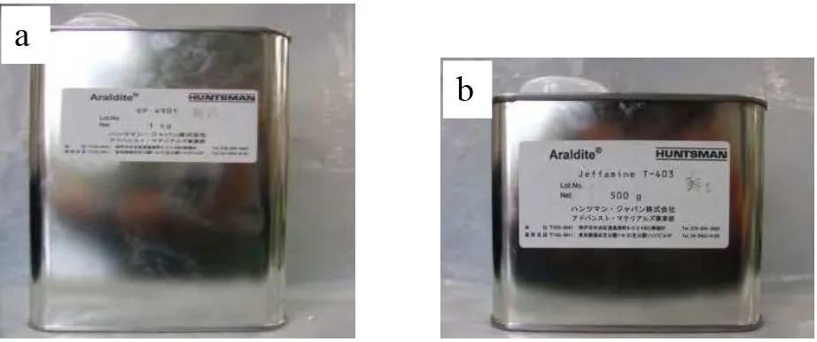
In this study, bisphenol-F type epoxy resin (EP-4901, Density: 1.19 Mg/m3) was used as
a matrix material, and polyetheramine hardener (Jeffamine T-403, Density: 0.978 Mg/m3;
Huntsman Co., Ltd.) was used as a curing agent as shown in Fig. 2.2. Both EP-4901 and
Jeffamine T-403 were mixed in the weight ratio of 100:46 to produce a thermosets resin.
Regarding reinforcement, nanoclay (Nanomer®I.28E, Bulk density: 0.25-0.30 Mg/m3; Nanocor
Inc.) was used as shown in Fig. 2.3. As described in earlier reports, clay particles can be
dispersed properly throughout the polymer matrix despite small weight percent values [9, 18,
21–23]. Consequently, it is expected that the clay particles can create much higher surface area
for polymer/filler interaction than conventional micro-order clays can.
Fig. 2.2 Overview of (a) bisphenol-F type epoxy resin and (b) polyetheramine hardener.
a
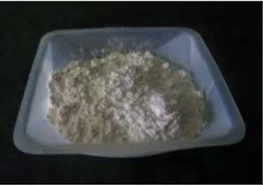
Fig. 2.3 Overview of nanoclay powder, Nanomer®I.28E.
2.2.2 Specimen fabrication
First, 1 phr, 3 phr, or 5 phr of nanoclay amounts were measured. They were mixed with
EP-4901 epoxy resin in a beaker with a mechanical stirring device (PM-201; As-One Corp.) at
2500 rpm for about 3 min. Then, the mixture was mixed further using an ultrasonic homogenizer
device (Branson Sonifier 450; CSC Co.) for another 10 min. An overview of the mechanical
stirring device and the ultrasonic homogenizer are shown in Fig. 2.4. During the sonication
process, the beaker was placed in cold water to avoid increasing the solution’s temperature [9].
The solution’s temperature was measured using a thermometer every one minute. Subsequently,
the Jeffamine T-403 hardener was added to the solution and was stirred manually for about three
more minutes at room temperature.
Then, nanoclay–epoxy resin solution was poured into a metallic mold as shown in Fig.
2.5. A mold lubricant (QZ13; Huntsman Co., Ltd.) was applied beforehand to prevent adhesion
to the metallic mold of the epoxy resin. The mold was then placed in a vacuum pump for 10 min
to remove air bubbles from the resin. The specimens were cured completely after placing them in
nanoclay volume fractions of 1 phr, 3 phr, and 5 phr specimens were 0.007, 0.019, and 0.032
respectively. The overview of vacuum pump and the homo-isothermal drier are shown in Fig. 2.6.
The specimen dimensions of tensile and fatigue tests are presented in Fig. 2.7. The
thickness and width of each specimen were measured respectively at three points: both ends and
the center of the gauge part. These average values were recognized respectively as the specimen
thickness and width. Then, the aluminum tabs were attached to both ends of the specimens using