UNIVERSITI TEKNIKAL MALAYSIA MELAKA
DESIGN AND ASSEMBLY ANALYSIS OF DIFFERENTIAL
GEAR BOX FOR UTeM FV CAR
This report submitted in accordance with requirement of Universiti Teknikal Malaysia Melaka (UTeM) for the Bachelor Degree of Mechanical Engineering
Technology (Automotive) with Honours
by
MUHAMMAD SAFUAN BIN MD SALLEH
B071210433
910904115445
UNIVERSITI TEKNIKAL MALAYSIA MELAKA
BORANG PENGESAHAN STATUS LAPORAN PROJEK SARJANA MUDA
TAJUK: Design and Analysis of Differential Gear Box for UTeM FV Car
SESI PENGAJIAN: 2014/2015 Semester 1
Saya MUHAMMAD SAFUAN BIN MD SALLEH mengaku membenarkan Laporan PSM ini disimpan di Perpustakaan Universiti Teknikal Malaysia Melaka (UTeM) dengan syarat-syarat kegunaan seperti berikut:
1. Laporan PSM adalah hak milik Universiti Teknikal Malaysia Melaka dan penulis. 2. Perpustakaan Universiti Teknikal Malaysia Melaka dibenarkan membuat salinan
untuk tujuan pengajian sahaja dengan izin penulis.
3. Perpustakaan dibenarkan membuat salinan laporan PSM ini sebagai bahan pertukaran antara institusi pengajian tinggi.
4. **Sila tandakan ( )
SULIT
TERHAD
TIDAK TERHAD
(Mengandungi maklumat yang berdarjah keselamatan atau kepentingan Malaysia sebagaimana yang termaktub dalam AKTA RAHSIA RASMI 1972)
(Mengandungi maklumat TERHAD yang telah ditentukan oleh organisasi/badan di mana penyelidikan dijalankan)
( )
iv
DECLARATION
I hereby, declared this report entitled “Design and Analysis of Differential Gear Box for UTeM Fv Car” is the results of my own research except as cited in references.
Signature : ………
Name : ………
v
APPROVAL
This report is submitted to the Faculty of Engineering Technology of UTeM as a partial fulfillment of the requirements for the Bachelor Degree of Mechanical Engineering Technology (Automotive) with Honours. The member of the supervisory is as follow:
vi
ABSTRACT
vii
ABSTRAK
viii
DEDICATIONS
I dedicate this thesis to my family especially to my parent Mr. Md Salleh Bin Md Yusoff and my loving mother Mdm Saleha Binti Abd Rahim for nursing me with affections and love lecturer at UTeM especially for my supervisor Dr. Muhammad
ix
ACKNOWLEDGMENTS
In the Name of ALLAH, the Most Gracious, the Most Merciful. Alhamdulillah, all praises to ALLAH for the strengths and His blessing for me to complete this project even though there are many difficulties and hardship along the way.
I would like to express my appreciation and deep respects to my supervisor Dr Muhammad zahir Bin Hassan, for his constant guidance, and encouragement as well as critical comment throughout this project. My thanks go to all my lecturers who have taught me, directly or indirectly, for all these four years. Also to all my friends, thank you for the help and friendship.
Lastly, thanks to my beloved father, mother, and my family, who have been the loveliest advisors, giving me the constant support, love, care and inspiration throughout my campus life. To all mentioned the above, this final year project report will not be realized without you. May ALLAH bless all of you.
x
TABLE OF CONTENTS
DECLARATION ... iv
APPROVAL ... v
ABSTRACT ... vi
ABSTRAK ... vii
DEDICATIONS ... viii
ACKNOWLEDGMENTS ... ix
TABLE OF CONTENTS ... x
LIST OF FIGURES ... xv
LIST OF TABLE ... xvii
LIST OF SYMBOLS AND ABBREVIATIONS ... xviii
CHAPTER 1 ... 1
1.0 Introduction of Differential Gearbox... 1
1.1 History of Differential ... 2
1.2 Problem statement ... 2
1.3 Aim and Objective of Research ... 3
1.3.1 Aim ... 3
1.3.2 Objective ... 3
1.4 Organization Thesis ... 4
CHAPTER 2 ... 5
xi
2.1.1 Engine ... 7
2.1.2 Clutch ... 8
2.1.3 Transmission ... 8
2.1.3.1 Manual Transmission ... 8
2.1.3.2 Automatic Transmission ... 9
2.1.4 Tire ... 10
2.1.5 Differential ... 11
2.2 Type of Wheel Drive ... 12
2.2.1 All-Wheel Drive (AWD)... 12
2.2.2 Front Wheel Drive... 13
2.2.3 Rear Wheel Drive ... 13
2.3 Type of Differential ... 14
2.3.1 Limited Slip Differential (LSD) ... 14
2.3.2 Locked Differential ... 15
2.3.3 Open Differential ... 16
2.3.3.1 Purpose of Open Differential ... 16
2.3.3.2 Functional Description of Open Differential ... 17
2.3.3.3 Loss of Traction ... 18
2.3.3.4 Use of Open Differential for Utem FV Car ... 21
2.3.3.5 Automobile Differential Gear Train ... 21
2.3.3.6 Gear Box Casing ... 23
xii
Advantages of bevel gear ... 23
Disadvantages of bevel gear ... 24
2.4 Software and Theoretical application ... 24
2.4.1 Finite Element Analysis ... 24
2.4.2 Solid Work ... 25
3.1.2.1 Assembly All Part ... 30
3.1.2.2 Crown Assembly Exploded View... 31
3.2 Material Selection ... 31
3.2.1 Cast Iron ... 31
3.2.2 Aluminium Alloy ... 32
3.3 Analysis procedure Using Solid Work Simulation ... 33
3.4 Calculated Force using Theoretical Method... 36
3.4.1 Centrifugal force ... 36
3.4.2 Speed Velocity ... 36
3.4.3 Force Acting to the differential at 1000 RPM and 5000 RPM ... 37
CHAPTER 4 ... 38
xiii
4.2 Units ... 40
4.3 Material properties ... 41
4.3.1 Grey Cast Iron ... 41
4.3.2 Aluminum Alloy ... 41
4.4 Fixture Geometry ... 42
4.5 Load ... 43
4.5.1 1000 RPM ... 43
4.5.2 5000 RPM ... 43
4.6 Mesh information ... 44
4.7 Result ... 45
4.7.1 1000 RPM ... 46
4.7.1.1 Cast Iron ... 46
4.7.1.2 Aluminum Alloy ... 47
4.7.2 5000 RPM ... 48
4.7.2.1 Cast Iron ... 48
4.7.2.2 Aluminum Alloy ... 49
4.8 Discussion ... 50
4.8.1 Comparison between cast iron and aluminium alloy at 1000 RPM ... 50
4.8.2 Comparison between cast iron and aluminium alloy at 5000 RPM ... 51
4.8.3 Bar chart of Displacement between 1000 RPM and 5000 RPM ... 52
4.8.4 Bar chart of Stress between 1000 RPM and 5000 RPM ... 53
xiv
CHAPTER 5 ... 55
5.0 Introduction ... 55
5.1 Summary of Research ... 55
5.1.1 Summary of Research ... 55
5.2 Achievement of Research Objectives ... 56
xv
Figure 2.1: Overview of Literature Review ... 5
Figure 2.2: Topology of the powertrain System (Makaran, 2007) ... 6
Figure 2.3: Limited Slip Differential (Gawande et al., 2008) ... 15
Figure 2.4: Limited Slip Differential (Gawande et al., 2008) ... 16
Figure 2.5: Component of open differential (Taylor, 2010) ... 17
Figure 2.6: Sum of differentiate rotation rate and Torque ratio formula ... 19
Figure 2.7: Rotation flow (Damjan, 2012) ... 20
Figure 2.8: Automobile Differential Complete Schematic (Kobal, 2006) ... 21
Figure 2.9: Automobile Wheel Drive without Differential (Kobal, 2006) ... 22
Figure 2.10: Automobile Differential Alone (Kobal, 2006) ... 22
Figure 2.11: Bevel gear of open differential ... 24
Figure 2.12: Example stress movement (Beer and Jonston, 2006) ... 26
Figure 2.13: Graph of Stress vs strain (Beer and Jonston, 2006) ... 26
Figure 3.1: The flow chat of this research... 27
Figure 3.2: Crown gear ... 28
Figure 3.3: Pinion ... 29
Figure 3.4: Planet gear ... 29
Figure 3.5: Sun Gear ... 29
Figure 3.6: Main shaft pinion ... 30
Figure 3.7: Assembly image ... 30
Figure 3.8: Crown Assembly ... 31
Figure 3.9: Design analysis flow chart ... 33
Figure 3.10: Additional spur gear parameter (Stoker, 2009) ... 34
Figure 3.11: Finite element mesh of spur gear ... 35
Figure 3.12: Formula to calculate Centrifugal force ... 36
Figure 3.13: Formula to Calculate Speed Velocity ... 36
Figure 4.1: Model information ... 39
Figure 4.2: Grey Cast Iron properties ... 41
Figure 4.3: Aluminium Alloy properties ... 42
Figure 4.4: Fixture geometry ... 42
Figure 4.5: Normal force at 1000 RPM ... 43
Figure 4.6: Normal force at 5000 RPM ... 43
Figure 4.7: Meshing line formed at differential surface ... 44
xvi
xvii
Table 3.1: Mechanical Properties of Cast Iron... 32
Table 3.2: Mechanical Properties of Aluminum Alloy ... 32
Table 4.1: Study properties ... 40
Table 4.2: Unit used in this analysis ... 40
Table 4.3: Comparison at 1000 RPM. ... 50
xviii
LIST OF SYMBOLS AND ABBREVIATIONS
P = power Diameter of pinion =DP
Equivalent no of teeth on pinion = TEP
Equivalent no of teeth on gear = TEG
WT = tangential tooth load
K =load stress factor Ww=wear load Torque =T
xix
N = Rotation per minute (RPM)
Fc = Centrifugal force
M = mass
1
CHAPTER 1
INTRODUCTION
1.0 Introduction of Differential Gearbox
Differential is a device, usually but not necessarily employing gears, capable of transmitting torque and rotation through three shafts, almost always used in one of two ways in one way, it receives one input and provides two outputs this is found in most automobiles and in the other way, it combines two inputs to create an output that is the sum, difference, or average, of the inputs (Veeranjaneyulu and Babu, 2012).
Heng Sun had a detailed study to the differential gear trains about its force and efficiency (Heng, 1990). Shaolie and Cao had a research about the movement of the differential gear trains under the inotropic effect (Cao and Shaolie, 1997). A vehicle's wheels rotate at different speeds, mainly when turning corners. The differential is designed to drive a pair of wheels with equal torque while allowing them to rotate at different speeds. A conventional "open" (non-locked or otherwise traction-aided) differential always supplies close to equal (because of limited internal friction) torque to each side (Chocholek, 1988).
2
It is not known who developed differential gear system. It seems obvious that the idea is older than many of Leonardo da Vinci's (1452-1519) innovations. English innovator James Starley (1830-1881), known as " Father of the Bicycle Industry', utilized a differential apparatus system as a part of an exceptional sewing machine in around 1850. In 1877 he utilized the differential gear as a part of a street vehicle. As far as anyone knows, differential gear was utilized as a part of a street vehicle surprisingly by German Rudolph Ackerman in 1810. Discoveries in China demonstrate the presence of this component going back to around 300. In the year 1900 a greatly complex Antikythera system (named after nearby antikythera island of Greece, where the ship was found) was found in a boat wreck. The component was a precisely composed and created in bronze and wood. It was a kind of computer to compute the position of planets and stars (Kobal, 2006). Others analyse the force stream and cross section productivity of the differential gear trains demonstrates that while cornering, the inward wheel needs to travel a shorter separation than the external wheel, so with no differential, the outcome is the internal wheel turning and the external wheel dragging. This outcomes in troublesome and eccentric taking care of, harm to tires and streets, and strain on (or conceivable disappointment of) the whole drive train (Baoxian and Wenfeng, 1999). It takes almost no torque to turn the side on elusive ice, and on the grounds that a differential parts torque similarly to every side, the torque that is connected to the side that is on black-top is restricted to this sum (Bonnick and Allan, 2001).
1.2 Problem statement
3
especially for UTeM FV car. However, differential must build using harden and withstand high torque material. Thus Differential gear box needs to be redesigned providing energy saving by weight reduction, providing internal damping, reducing lubrication requirements and have high tensile strength, elastic modulus, poison‟s ratio, mass density and shear modulus without increasing cost. A proposed way to distribute the power to the wheel is to use the concept of gearless differential of which a review has been reported by Provatidis (Provatidis, 2003). To create some lightweight and compact differential, the detail analysis is conducted using Solid Work simulation to verify the best material for the gears in the gear box at higher speeds by analysing stress, displacement and also by considering weight reduction. This study was carry out to reduce the weight of UTeM FV car and improve the car to take a cornering at high speed without over steer or understeer issue.
1.3 Aim and Objective of Research
1.3.1 Aim
The overall aim of this research is focus to develop the mechanical design and static analysis on the assembly of gear in gear box when the UTeM FV car differential transmit power at 1000 rpm and 5000 rpm. Besides that, this analysis research also conducted by varying the material for gear. The selected material is Grey Cast Iron and Aluminium Alloy. The analysis is conducted to verify the best material for the gears in the gear box at higher speeds by analysing stress, displacement and also by considering strain.
Design calculations are done on the differential of Daihatsu Mira L2 by varying materials and speeds. Differential gear is modelled in Solid Work. Analysis is done on the differential by applying force at static. Analysis is carried out using Solid Work simulation.
1.3.2 Objective
Based on the problem statement the objective have been drawn: I. To design and analyse differential for UTeM FV car
4
Chapter 2: Review for any available journal or thesis that had been made preciously for any connections with the purpose of this analysis. Any journal that can be found to have any information regarding some of the analysis.
Chapter 3: Making a mere draft on how the analysis project can be done to verify each and every single step. Making sure the analysis is done according and save time while doing the analysis. Appointing the material that are usually easy to be fine in the market by doing a survey for types of differential and select the best material for analysis. Showing the list of material and brand available. Sketch all of component that be related to differential and all of the component design need to assemble using assemble design at Solid Work 2015. List of all material chosen and its behaviour using Solid Work Simulation. Knowing the percentage and it effect on other material.
Chapter 4: Showing the analysis result and its properties. Discussion on what size and type of differential system. Shows the step of making a dimension for drawing use in analysis. Showing how the software been use to make an exact drawing with the type of differential material chosen.
5
CHAPTER 2
LITERATURE REVIEW
2.0 Introduction
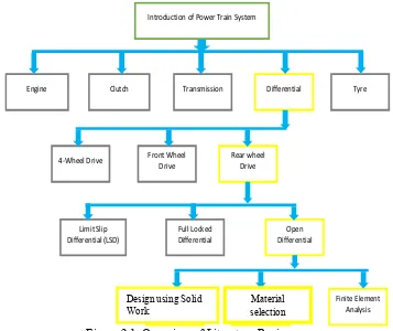
The subject of differential has produced a significant volume of writing which incorporates various speculations that have been planned to clarify the systems of differential. This chapter begins with an introduction to the automotive powertrain system, to give an overview of differential components and their function. The scientific findings are categorised into theoretical, Solid Work Simulation is used to tackle and analyse the best material for differential. A review of differential analysis is also described. The consequent segment talks about exploratory examinations that have been utilized to ensure this studies achievement. The structure of the chapter is shown in Figure 2-1.
Figure 2.1: Overview of Literature Review
Introduction of Power Train System
Engine Clutch Transmission Differential Tyre
4-Wheel Drive Front Wheel Drive
6
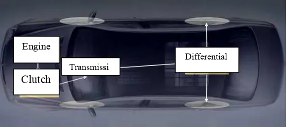
The drive train serves two capacities. It transmits power from the motor to the drive wheels, and it changes the measure of torque. Force is the rate or speed at which work is performed. Torque is turning or bending power. Various proportion gearboxes are important on the grounds that the motor conveys its greatest force at specific velocities, or RPM (Rotations every Minute). With a specific end goal to utilize the same motor RPM's at distinctive street speeds, it is important to change the apparatus proportion between the motor and the drive wheels. The main component of power train is shown in Figure 2-2.
Figure 2.2: Topology of the powertrain System (Makaran, 2007)
There are really two arrangements of gear in the drive train, the transmission and the differential. The transmission allows the gear ratio to be balanced, and the differential lets the drive wheels turn at difference speed. Manual transmissions ordinarily have four or five speed. A transmission is a speed and power changing device installed at some point between the engine and driving wheels of a vehicle. It provides a means for changing the ratio between engine RPM and driving wheel RPM to best meet each particular driving situation. Torque is derived from power. The amount of torque obtainable from a source of power is proportional to the distance from the center of rotation at which it is applied.
Engine
Clutch Transmissi