UNIVERSITI TEKNIKAL MALAYSIA MELAKA
DESIGN AND SIMULATION OF GO-KART ACTIVE
REAR SPOILER AIR FOIL SHAPE USING
COMPUTATIONAL FLUID DYNAMICS (CFD)
SIMULATION
This report submitted in accordance with requirement of the Universiti Teknikal Malaysia Melaka (UTeM) for the Bachelor’s Degree in Mechanical Engineering
(Automotive Technology) (Hons.)
by
CARLA REGINA YALING B071210374
930122-13-6338
Tarikh : Tarikh :
UNIVERSITI TEKNIKAL MALAYSIA MELAKA
BORANG PENGESAHAN STATUS LAPORAN PROJEK SARJANA MUDA
TAJUK: DESIGN AND SIMULATION OF GO-KART ACTIVE REAR SPOILER AIR FOIL SHAPE USING COMPUTATIONAL FLUID DYNAMICS (CFD) SIMUATION
SESI PENGAJIAN: 2015/16 SEMESTER 1/2
Saya CARLA REGINA YALING
mengaku membenarkan Laporan PSM ini disimpan di Perpustakaan Universiti Teknikal Malaysia Melaka (UTeM) dengan syarat-syarat kegunaan seperti berikut: 1. Laporan PSM adalah hak milik Universiti Teknikal Malaysia Melaka dan penulis. 2. Perpustakaan Universiti Teknikal Malaysia Melaka dibenarkan membuat salinan
untuk tujuan pengajian sahaja dengan izin penulis.
3. Perpustakaan dibenarkan membuat salinan laporan PSM ini sebagai bahan pertukaran antara institusi pengajian tinggi.
** Jika Laporan PSM ini SULIT at au TERHAD, sila lampirkan surat daripada pihak berkuasa/ organisasi
berkenaan dengan menyat akan sekali sebab dan t empoh laporan PSM ini perlu dikelaskan sebagai
DECLARATION
I hereby, declared this report entitled “Design and Simulation of Go-Kart active rear spoiler air foil shape using computational fluid dynamics (CFD) simulation”
is the result of my own research except as cited in references.
Signature : ………....
Author’s Name : ………
APPROVAL
This report is submitted to the Faculty of Engineering Technology of UTeM as a partial fulfillment of the requirements for the degree of Bachelor of Engineering Technology (Automotive Technology) (Hons.). The member of the supervisory is as follow:
………..
i
ABSTRAK
ii
ABSTRACT
iii
DEDICATION
I would like to dedicate this to my father, Mr Yaling Chuanteck and my mother, Mrs Rosnah Yehat, my two lovely brothers, Hans De Rieviera Yaling and Ferdinand De Franco Yaling, my supervisor, Mr Mohd Faruq bin Abdul Latif, co-supervisor, Mr Mohd Suffian bin Ab Razak and my friends for supporting me from the beginning
iv
ACKNOWLEDGEMENTS
I am sincerely appreciative and grateful to my supervisor Mr Mohd Faruq bin Abdul Latif for giving me chances and opportunity to get involved in this project. A lot of thanks to him for his ideas, guidance, supports and encouragements in making this research possible. I am thankful to him for the time spent on correcting and proofreading my mistakes in writing this Projek Sarjana Muda (PSM) thesis.
My sincere thanks to my Co-Supervisor Mr Mohd Suffian bin Ab Razak for his dedication and guidance in teaching me for the writing of this thesis and how to use the software. Without the help of my Supervisor and Co-Supervisor, it is possible for me to complete this project on time.
Thanks to my beloved parents, Mr Yaling and Mrs Rosnah who always support me and give me courage since the beginning of this project. Their words have give me strength to complete this thesis project. My sincere thanks to my all my friends for their support and guidance during the project period.
v
LIST OF ABBREVIATION, SYMBOLS AND NOMENCLATURE x
vi
5.2 Lift coefficient, �� and drag coefficient, ��34T 72
5.2 Streamlines, pressure contour and velocity contour 73 5.3 Straight acceleration and cornering acceleration 75
CHAPTER 6 79
CONCLUSION & RECOMMENDATION 79
6.1 Introduction 79
6.2 Conclusion 79
6.3 Achievement of Research Objectives 79
6.4 Problem faced during research 80
6.5 Future recommendation 80
REFFERENCES 81
vii
LIST OF TABLES
Table 1 Dimple shapes of golf balls tested 30
Table 3 Dimensions of Spoiler 51
Table 4.2.1 Benchmark Table 55
Table 4.2.2 0° angle of attack 55
Table 4.2.3 8° angle of attack 56
Table 4.2.4 12° angle of attack 56
Table 4.2.5 15° angle of attack 56
Table 4.2.6 Drag coefficient, �� and Lift coefficient, �� 57 Table 5.1 Description selected model 71
viii
LIST OF FIGURES
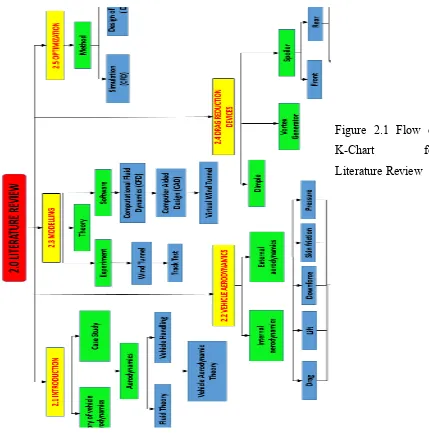
Figure 2.1 Flow of K-Chart for Literature Review 4
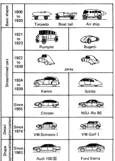
Figure 2.2 The four primary phases of cars aerodynamics 6
Figure 2.3 Streamtubes flowing over an aerodynamic body 8
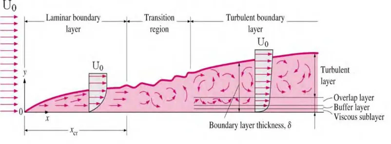
Figure 2.4 Development of a boundary layer 9
Figure 2.5 Flow separation in an adverse pressure gradient 10
Figure 2.6 Directional Control Axis System 11
Figure 2.7 Configuration of optimized plan 13 Figure 2.8 Rear wing with 0◦ AOA 14
Figure 2.9 Graph Aerodynamic Coefficient for rear wing v/s Angle of Attack Figure 2.16 Schematic description of a circa year 2000 Indy car underbody
and a simple flat-plate model with vortex generator 31
Figure 2.17 Comparison between polyhedral (left) and trimmer (right) meshing
34
Figure 3.1 The Flow Chart of Methodology 36
Figure 3.2 Measuring tape 37
Figure 3.3 Go-Kart steering 37
Figure 3.4 Go Karts panels 37
Figure 3.5 Go-Kart wheel 38
Figure 3.6 Go-Kart 2 stroke engine 38
Figure 3.7 Go-Kart chasis 39
ix
Figure 3.11 Go-Kart front bumper 42
Figure 3.12 Go-Kart front panel 42
Figure 3.13 Go-Kart front and rear wheel 43 Figure 3.14 Manikin (driver), Go-Kart chasis, engine and driver seat 43 Figure 3.15 Benchmark full design of Go-Kart with a driver manikin
using CATIA V5R20
44
Figure 3.16 Meshing of benchmark design of Go-Kart model using Altair Hypermesh 13.0
45
Figure 3.17 Virtual Wind Tunnel sizing for the benchmark of Go-Kart mode
46
Figure 3.18 Typical cross-section of wing/Spoiler 47 Figure 3.19 Selig 1223 airfoil plotter from website 48 Figure 3.20 Example of airfoil coordinates of 0° in GSD_PointSplineLoft
from Excel
49
Figure 3.21 Imported point and spline of angle of attack 0° 50 Figure 3.22 Spoiler design model with 0° angle of attack 50 Figure 3.23 The quality Index of meshing of Go-Kart model with spoiler 52 Figure 3.24 Simulation of Go-Kart model with spoiler using Virtual Wind
Tunnel
53
x
Figure 4.4.5 15° angle of attack pressure contour 66 Figure 4.5.1 Benchmark velocity vector 67 Figure 4.5.2 0° angle of attack velocity vector (full body 67 Figure 4.5.3 0° angle of attack velocity vector (spoiler) 68 Figure 4.5.4 8° angle of attack velocity vector (full body) 68 Figure 4.5.5 8° angle of attack velocity vector (spoiler) 68 Figure 4.5.6 12° angle of attack velocity vector (full body) 69 Figure 4.5.7 12° angle of attack velocity vector (spoiler) 69 Figure 4.5.8 15° angle of attack velocity vector (full body) 70 Figure 4.5.9 15° angle of attack velocity vector (spoiler) 70 Figure 5.3 Aerodynamic requirements through a corner and straight road 76
LIST OF ABBREVIATION, SYMBOLS AND
NOMENCLATURE
A - Area
AOA - Angle of attack
xi DoE - Design of Experiment
D - Drag
d - Diameter
H - Height
ICG - Interactive Computer Graphic L - Lift force
M - Mach number
NASA - National Aeronautics & Space Administration PIV - Particle Image Velocity
1
CHAPTER 1
INTRODUCTION
1.0 Background
Go–kart or kart is a small four wheeled vehicle without a traditional suspension. It was considered as a non-life threatening and a very safe motorsport with rare risk of injuries. Go-karts come in various forms and shapes start from the motorless models to high-powered racing machines such as the Superkarts which has the ability to beat other racing cars on long circuits. Karting is commonly perceived as the stepping stone to the higher ranks of motorsport (Aberdeen Lim Jian Rong,2011)
2 1.1 Problem Statement
In the last decade, manufactures and teams has make several effort in advanced design and setup procedure as their support in addressed the aerodynamic drag forces in Go-Kart competition (Biancolini, 2004). About 50 to 60% of total fuel energy is lost due to the burning fuel in accelerating a racing car or road vehicle to overcome the aerodynamic drag. Faster acceleration is needed in winning a race and drag reduction is the goal that need to be achieve(Hassan, Islam, Ali, & Islam, 2014). Besides that, aerodynamic downforce has been a greater value in reducing lap times than low drag on high powered race cars. The purpose of downforce is allowing a car to travel faster through a corner by increase the vertical forces on tires, thus create more grip (Kieffer, Moujaes, & Armbya, 2006). By adding rear wing to Go-Kart, it can provide enough downforce, minimum aerodynamic drag and good directional stability (Yang, Gu, & Li, 2011).
Current research suggested the installation of rear wing with an appropriate angle of attack can reduce aerodynamic lift coefficient (Breu, Guggenbichler, & Wollmann, 2008) and improve the wake structure of vehicle (Jiang & Kang, 2005). The wake effect can be estimated using particle image velocity (PIV) to analyse the flow behind a vehicle with or without spoiler (Kim, Kim, Sung, Kim, & Choi, 2006).Computational fluid dynamic is feasible for the numerical simulation of automobile airflow which it provides the reference for the automotive development with spoiler (Hai-Tao, 2011). The turbulent simulation (using a k–ε model) of the airflow on the front and rear wings can performed using computational fluid dynamics with different angles of attack and effect of the ground on the front wing (Kieffer et al., 2006). Computer Aided Design used in design model and create meshes for CFD simulation with the recommendation of angle of attack (Chandra, 2011).
3
aerodynamic hopefully can establish a world speed record for Go-Kart industry (Tor, n.d. 2006).
1.2 Objectives
The objectives of this project are:
1. To design aerodynamic rear spoiler for Go-Kart with variable downforce. 2. To analyse the suitable angle of attack for the Go-Kart active rear spoiler
using the computational fluid dynamic simulation.
1.3 Scope of Study
4
CHAPTER 2
LITERATURE REVIEW
2.1 IntroductionIn this chapter, the definitions and theories shall be defined and explained. This chapter discuss the literature based on the flow of K-Chart as shown in Figure 2.1. K-Chart has been used for research planning and monitoring because of the
Figure 2.1 Flow of
K-Chart for
5
systematically organizing research in the form of Tree Diagram which enable better flow in writing the literature review. This literature review has been divided into five topics. The first topic deals with introduction that explained more about the developments and history of aerodynamics and also the current research which related to this thesis. Second topic explained more about the overall scopes of vehicle aerodynamics that affect to the vehicle handling. The third topic discussed on the methodology and applications used for this thesis project. The fourth topic explained the devices that were used for drag reduction and downforce. From this topics, the theory and design of active rear spoiler has been elaborated more which related to this thesis project. Lastly, the fifth topic deals with the method involved in optimizing the design of the model project.
2.1.1 History of vehicle aerodynamic
The interaction between the air flow and the ground, and the complicated geometrical shapes that are involved in motor vehicle aerodynamics has make it a complex subject. The road of vehicle aerodynamics has been treated by Barnard (1996) and Hucho (1998a) who gives very readable account and particularly comprehensive treatment. In the 1980s, the main developments with vehicle aerodynamics occurred and the use of low-drag vehicles has become common until now. Vehicles are still designed by body stylist and aerodynamicist then refinements the shape for giving drag reduction and other aerodynamic improvements. Aerodynamic makes it major impact through the contribution to road load on vehicles (Richard Stone & Jeffrey K. Ball, 2004)
6
Figure 2.2 : The four primary phases of cars aerodynamics (Wolf-Heinrich Hucho,1998).
Torpedo shape car built by Camille Jenatzy was the oldest vehicle developed according to aerodynamic principle as the exposed wheel and driver which were not integrated had led to a considerable drag increase. Alfa Romeo built in 1913 with body shape of an airship, which were little suited in automobile aerodynamics. However, due to poor roads and low engine power, it contribute to low speed and subordinate role of aerodynamic drag (Wolf-Heinrich Hucho,1998).
The streamlined bodies design started simultaneously after the First World War which has the shape of aerofoil viewed on the top, streamlined roof and uncovered wheels that result to an increase of drag and more significant to vehicle body improvement of aerodynamic quality. Hucho, Janssen and Emmelmann represent one approach of method in optimize body details. Styling, safety, comfort and production were the requirement to practical automotive engineering in adapting aerodynamics.(Wolf-Heinrich Hucho,1998).
7
designers had succeeded in building cars with low drag coefficient and achieved a shape of a car with the concept of aerodynamics (Thomas D. Gillespie, 1992).
2.1.2 Aerodynamics
Aerodynamics is the branch of dynamics that treats of the motion of air and other gaseous fluids and of the forces acting on the bodies in motion relative to such fluids (Webster’s Third New International Dictionary).Aerodynamics is the science of the motion of gases and the effect of those motions on various bodies or surfaces in the flow (John David Anderson,1997). Aerodynamics is closely related to hydrodynamics and gas dynamics, which represent the motion of liquid and compressible-gas flows respectively (Gary A. Flandro, Howard M. McMahon & Robert L. Roach, 2012).Aerodynamics can be classified in a number of ways which are the external aerodynamics and internal aerodynamics. External aerodynamics deal with external flow over a body. It is the prediction of forces, moments, and aerodynamic heating associated with a body. Internal aerodynamics deals with flows internally within ducts. It study the flow through passage in solid objects respectively (John David Anderson,1997).
2.1.2.1 Fluid Theory
Bernoulli Equations deals with pressure and velocity of air that flow smoothly around a body. It describes the conditions existing in the free stream, outside the boundary layer. It is possible in prediction of the surface pressures and lift for various types of shapes (William F. Milliken & Douglas L. Miliken, 1995). Bernoulli’s Equation states the sum of static pressure and dynamic pressure of the air will be constant as it approaches the vehicle. The equation is as below:
8
�� + 1�2 ρ �2 =�� (2)
Where:
Ρ = Density of air
V= Velocity of air (relative to car)
Streamlines is the air streams along line and a bundle of streamlines forms a streamtube. Streamtube can be visualized from the smoke streams used in a wind tunnel as shown in Figure 2.3 (Thomas D. Gillespie, 1992).
Figure 2.3 : Streamtubes flowing over an aerodynamic body (Wolf-Heinrich Hucho) A streamtubes is composed of a frictionless and incompressible fluid and is an isolated system. The path of successive air particles in a steady flow is called a streamline. Static pressure is the pressure in the airstream (William F. Milliken & Douglas L. Miliken, 1995).The streamtubes split as the flow approaches the vehicle with some going above vehicle and others below the vehicle. One streamline must go straight to the body and stagnate. At that point the relative velocity gone to zero and the static pressure observed will be �� (Thomas D. Gillespie,1992).
9
velocity as the flow turns to follow the hood (Thomas D. Gillespie,1992). This is because the higher velocity of the flow over the vehicle roof resulting to a lower pressure than under the lower body, where the flow velocity is low (Richard Stone & Jeffrey K. Ball, 2004).
Bernoulli’s Equation explain how the pressure and velocity vary in the gross air flow over a car body. The air simply flow up over the roof and down the car the back side of the vehicle and exchange the pressure for velocity at the front with the absence of friction. However, drag is produced due to the air friction on the surface of the vehicle and main flow down back side of the vehicle. This can be explained from the understanding the action of boundary layers in the flow over an object (Thomas D. Gillespie,1992).
Figure 2.4 : Development of a boundary layer (Ganesh Visavale,2014)