UNIVERSITI TEKNIKAL MALAYSIA MELAKA
DEVELOPMENT OF VERTICAL BANDSAW MACHINE AND
JIG FOR CUSTOMIZED PLASTIC PRODUCTION
This report submitted in accordance with requirement of the Universiti Teknikal
Malaysia Melaka (UTeM) for the Bachelor Degree of Manufacturing Engineering
(Manufacturing Process)(Hons.)
by
WAN MUHAMAD FARHAN BIN WAN ZIN B051010129
880410-06-5383
FACULTY OF MANUFACTURING ENGINEERING
DECLARATION
I hereby, declared this report entitled “Development of Vertical Bandsaw Machine and Jig for Customized Plastic Production” is the results of my own research
except as cited in references.
Signature : ………
Author’s Name : WAN MUHAMAD FARHAN BIN WAN ZIN
APPROVAL
This report is submitted to the Faculty of Manufacturing Engineering of UTeM
as a partial fulfillment of the requirements for the degree of Bachelor of
Manufacturing Engineering (Process) (Hons.). The member of the supervisory is
as follow:
i
ABSTRAK
Projek ini membincangkan mengenai pembangunan dan aplikasi mesin ‘bandsaw’ menegak dan jig pemanasan. Pembinaan mesin dan jig di ambil kira dari segi fungsinya. Mesin ‘bandsaw’ menegak difabrikasi dengan menggunakan beberapa proses pembuatan yang terlibat. Kejayaan membangunkan mesin ‘bandsaw’
menegak untuk memotong plastik yang diubahsuai membolehkannya beroperasi
secara berulangan untuk tempoh yang berpanjangan tanpa kompromi. Penggunaan
peralatan moden dan teknologi sedia ada amat penting bertujuan untuk meningkatkan
lagi prestasi serta kecekapan mesin dan jig. Semua kenyataan yang dibincangkan
dipertimbangkan sebagai yang sesuai dengan pembangunan dan pembuatan sesuatu
produk. Selain itu, komponen yang dipilih adalah sesuai untuk membangunkan
rekaan yang terbaik. Pandangan dan cadangan dijelaskan setelah mesin dan jig
dibangunkan. Sistem ini dijangka akan menambah baikkan pengeluaran dalam
ii
ABSTRACT
This project discusses the development and application of the vertical bandsaw
machine and sintering jig. It will be measured by the functionality. The vertical
bandsaw machine and the sintering jig will be developed using several
manufacturing process involves. The successful vertical bandsaw machine for cutting
various type of customized plastic will be able to repeatedly perform its required task
for many years without compromise. Yet for all the modern tools and technology
available is to extend performance and efficiency. All sentences are discussed on the
methodology, the step used to develop the vertical bandsaw machine and sintering jig
will consider the best. The component size will be selected to make the good design.
The machine development was comment once the machine is completed. The
iii
DEDICATION
iv
ACKNOWLEDGEMENT
First and foremost, I would like to express my highest appreciation to my supportive
academic supervisor, Dr. Hadzley B. Abu Bakar. His supervision and support that
gave me truly helps during the period of conducting my thesis. His never-ending
supply of valuable advice and guidance has enlightens me and deeply engraved in
my mind.
Next, I would like to dedicate my thankfulness to machinery laboratory technicians,
who has been so warmth and kind to provide sincere assistance and good cooperation
during the training period. Their co-operation is much indeed appreciated. In
addition, I would like to thanks to FKP lecturers, for their assistance, which really
spends their time to teach me a lots of knowledge regarding to the design
development.
Last but not least, I would like to state my appreciation to the staff – Faculty of
Manufacturing Engineering, FKP, my friend and colleagues for supporting me and
v
2.2.1.1 Sizing Electric Motor for Motion Control 6
2.2.1.2 Start and Running Torque Requirement 7
2.2.1.3 Running or Operating Torque Equation 8
2.2.1.4 Electric Motor Application and Operation 8
2.2.2 Bandsaw Blade 11
2.2.3 Bearings 11
2.2.3.1 General Application Guidelines 12
vi 2.2.3.3 Ball Bearings Application and Overview 13
2.2.3.4 Miniature Bearing Application 14
2.2.3.5 Thin Section Bearing Application 15
2.2.4 Gears 16
2.2.6.1 Procedure for Design and Analysis of Shaft 26
2.3 Jigs and Fixtures 29
2.3.1 Application and Classification of Jig and Fixture 31
2.4 Location 32
2.4.1 Principle 32
2.4.2 Location Method 33
2.4.2.1 Location from Plane Surfaces 33
2.4.2.2 Location from Profile 34
2.4.2.3 Location from Cylinder 34
vii
3.2.1.1 Design of Vertical Bandsaw Machine 45
3.2.1.2 Design of Feeding Table 48
3.2.2 Design For Assembly 51
2.2.3 Selection of Materials and Processes 51
3.2.4 Best Design Concept 51
3.2.5 Design for Manufacture 51
3.2.6 Prototype 51
3.2.7 Suggestion for Simplification of Product 52
3.2.8 Identification Process 52
3.4.2 Material Selection for a New Product or New Design 56
3.4.3 Material Selection for Bandsaw Machine 57
3.4.3.1 Cover 57
3.4.3.2 Gear 59
3.4.3.3 V-Belt 59
3.4.3.4 Shaft 60
3.4.3.5 Bearings 60
3.5 Manufacturing Process Selection 61
CHAPTER 4: RESULT AND DISCUSSION 63
4.1 Development of Vertical Bandsaw Machine 63
viii 4.1.2 Components Assembly of Vertical Bandsaw Machine 66
4.2 Development of Sintering Jig 68
4.2.1 Fabrication Process of Jig’s Frame 68
4.2.2 Fabrication Process of Jig’s Clamp 71
4.2.3 Joining Process of Jig’s Wheels 73
4.3 Analysis on Vertical Bandsaw Machine 74
4.3.1 Burr Formation 74
4.3.2 Cutting by Using Handsaw 74
4.33 Cutting by Using Bandsaw Machine 75
4.4 Discussion 77
4.4.1 Overview of Bandsaw Machine Development 77
4.4.2 Overview of Sintering Jig Development 77
CHAPTER 5: CONCLUSION 79
5.1 Conclusion 79
5.2 Recommendation 80
REFERENCES 81
ix
LIST OF TABLES
2.1 Standard Groove Dimension 23
2.2 Deep Groove Dimension 23
3.1 Pugh Method Table for Bandsaw Machine 54
3.2 Pugh Method Table for Sintering Jig 55
3.3 Manufacturing Process for Bandsaw Development 62
x
LIST OF FIGURES
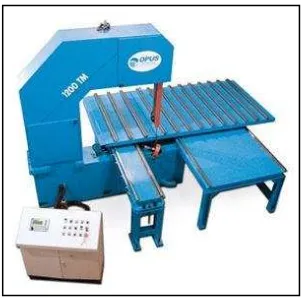
1.1 Vertical Bandsaw Machine with Feeding Table 2
1.2 Work piece Dimension 2
2.1 Cross Section of Synchronous Motor 8
2.2 Cross Section of Stepper Motor 9
2.8 Thin-section Bearings for Robots 16
2.9 Gearing System 16
3.1 Flowchart of Project Planning 42
3.2 Step Taken in a Design of a Vertical Bandsaw Machine 44
3.3 Bandsaw Design 1 45
3.4 Bandsaw Design 2 46
3.5 Bandsaw Design 3 47
3.6 Sintering Jig Design 1 48
xi
3.8 Sintering Jig Design 3 50
4.1 Measuring Process by Using Measuring Tape 64
4.2 Cutting Process of Bar Using Horizontal Bandsaw 64
4.3 Drilling Process 65
4.4 Measuring Process 68
4.5 Cutting Process of Material by Using Disc Cutter 69
4.6 Metal Inert Gas (MIG) Welding Equipment 69
4.7 The Frame Alignment and Stability is Checked by Using Water
Lever Scale 70
4.8 Clamp Locator 71
4.9 Threaded Screw 72
4.10 Steel Rod Handles for Threaded Screw 72
4.11 Wheel with a Lock Function 73
4.12 The Jig for Clamping the Customized Plastic 73
4.13 Large Burr Formation 75
4.14 Distortion Defect at the Joint of Sintered Plastic 75
4.15 Smaller Size of Burr Formation 76
xii
LIST OF ABBREVIATIONS, SYMBOLS AND
NOMENCLATURE
AC - Alternate Current
AISI - American Iron and Steel Institute
ASB - Acrylonitrile-butadiene-styrene
DC - Direct Current
HB - Brinell Hardness
HR - Rockwell Hardness
PP - Polypro
PET - Polyethylene Terephthalate
1
1.1 Background of project
In Malaysia, the technology of polymer processing is improved drastically and one
type of the polymer is the recycle plastic. The recycle plastic is widely used in the
various applications. One of the recycle plastic application is in the constructing the
structural support for load. The process that involve in production of customized
plastic is the sintering process. The sintering process is conducted in the large
sintering chamber. Therefore, the jig is needed in order to hold and press the
customized plastic in the sintering chamber.
The main function of jig and fixture is to hold and locate the work piece for the
various type of machining. Usually, the jig and fixture is used for the operation of
small parts. The special jig is needed to hold and press the customized plastic due to
large dimension of the structural support. The sintering process will be done by
Department of Civil Engineering at the University Tun Hussein Onn Malaysia.
After the customized plastic is sintered, it must be cut into various sizes for the
structural support platform. Usually, a plastic is cut by using laser cutting and water
jet abrasive particle, however it is only ideals for the thin part dimension because the
thickness of material can affected the cutting quality. The vertical band saw machine
is the most suitable machine to cut the large dimension of recycles plastic with the
minimum cost required.
INTRODUCTION
2 1m
1.2 Problem Statement
The structural support for load is produced by using the customized plastic. The raw
material of the customized plastic comes in a tubular shape with a length of 1 meter,
and then it is sintered to create a dimension 1m x 1m x 1m (Figure 1.1). The
structured of the structural support is honeycomb structure. In order to have a good
joining between each customized plastic, it must be press uniformly during sintering
process. Therefore, the special jig is needed to hold and press the customized plastic
to produce a structural support.
Figure 1.1: Structural support (Hasanah, 2013)
Occasionally, structural support material is produced from the customized plastic, it
is considered as a soft material and common technique to cut this material is by using
a vertical bandsaw machine. However, most vertical bandsaw just enable to cut about
20-30cm height (Figure 1.2). To cut 1m x 1m x 1m height of product with the good
surface finish, the machine have to be customized.
3
1.3Objectives
The main objective of this research is:
i. To develop a vertical bandsaw machine.
ii. To fabricate a jig for sintering process of customized plastic.
1.4 Scope of Project
The importance of the study is to develop and analyze or improve the already made
product that is available in the market. Base from the research and the analysis, the
best part is select and the design built to make a jig and vertical bandsaw. The
mounting of bandsaw machine also is one of the researches because the cutting
operation will performed repeatedly. Base of all these, an ideal jig and bandsaw
machine for the customized plastic production is developed, thus will reduce
work-related injuries, improve quality and productivity, and provide a good machining
4
2.1 Developing the bandsaw machine application
Band sawing uses a continuous band, welded to form a loop. The band sawing
process is continuous. The band is tensioned between two pulleys-known as
bandwheels-mounted on a bow (the nomenclature is derived from hack sawing). One of the band wheels is the “lay” or nondriven wheel. Generally, this wheel is arranged in an assembly which allows the band to be tensioned either mechanically or-more
usually in modern machinery-via a hydraulic cylinder. The other wheel is driven by
an electric motor and gearbox configuration. The band runs through a system of
guides-usually roller bearings and preloaded carbide pads-to keep it running true
through the material, mechanical variators arranged between motor and gearbox were
employed to provide variable band speed. More recently, frequency-regulated motors
feeding directly into the gearbox have become the normal.
Although a different design exist, bandsaws split into two basic configurations which
are vertical and horizontal, it is based on the attitude of the band. Vertical machines
are commonly used in tool room applications and in lighter structural applications.
Heavy-duty billet sawing and the heavier structural applications favor the horizontal arrangement since this allows a closed, “box” type construction whereby the bow assembly runs in a gantry straddling the material and rigidly attached to the base of
the machine. This setup allows maximum band tension and counteracts bow/blade
deflection. Lighter-weight horizontal machines often employ a pivot-mounted bow
which arcs in a similar fashion to the hack saw. (Manufacturing Engineering
Handbook, 2004)
LITERATURE REVIEW
5 When developing a new design of vertical bandsaw machine for machining
application, many of the time-tested classic design philosophies still apply. In
addition, with the advent of new technologies, particularly in motor and hydraulic
controls, many improvements and innovations are possible.
When embarking on a new design, one must consider many parameters which define
the problem to be solved. Many of these parameters are dependent on each other and
the design becomes an iterative process. First, one must consider the maximum live
load to be deployed by the bandsaw mounting and the desired cutting speed.
2.1.2 Materials of Choice
At this point, the material for the bandsaw machine and feeding table must be
decided. For most applications, steel is appropriate. If the bandsaw machine is meant
to be transportable, aluminium may be the material of choice. For some rare
applications such as a bandsaw machine is built to cut a high temperature workpiece,
selected and expensive materials such as titanium may be considered. Each of these
materials has their own unique characteristics and requires certain manufacturing
techniques. Although some end-users may feel that steels would have a superior
strength properties compared to aluminum, with a good method of machine
development and minimal maintenance, an aluminum bandsaw’s structure can
provide a good dimension stability of the machined work piece.
If ones decide that aluminum is required, manufacturing techniques become very
important. Due to the high distortion that can result, special techniques must be
6
2.2 Components on Vertical Bandsaw Machine
2.2.1 Electric Motor
Basically, an electric motor is the most important part in the machine especially
vertical bandsaw machine. The function of an electric motor in bandsaw machine is
to rotate the bandsaw blade which is attached to the wheels. The blade must suitable
to the bandsaw application so that the material being cut has good surface properties.
Besides that, the determination of electric motor also important in order to reduce the
machining time, production cost and labor cost. There is various type of electric
motor in the market which is depending on its application.
2.2.1.1 Sizing Electric Motor for Motion Control
To size an electric motor for a particular drive application the designer must first
analyze the mechanics of the drive application. The following must be determined:
(Edge Engineering, 2006)
a) Friction of the bearings, or other mechanical elements.
b) The weight or load to be driven by the electric motor.
c) Inertia of the mass to be moved or controlled. Acceleration and deceleration
forces should be analyzed.
d) Mechanical system type and number of linkages.
Friction – The friction may be determined by estimation, component specification or
by measuring by the use of a torque reading device or mechanism.
Weight or Mass – The mass may be calculated using 3D CAD, specific or direct
measurement.
Inertia – Inertia is the force required to accelerate of decelerate a mass. Inertia is used
7 Mechanical System – There are roughly four categories of mechanical drive systems.
a) Direct drive
b) Gear drive
c) Tangential drive
d) Lead-screw or worm-gear
2.2.1.2 Start and Running Torque Requirements, and Calculations.
When determining the torque requirements for an electric motor, consideration
should be given to the load and start time demands during the start duration,
operating torque, and peak load torque. The starting torque is dependant on the
number of times an electric motor will have to start in a given time, as well as, the
duration of the start cycle. The actual start torque applied should be many times
greater than the actual start torque required by the application. The greater difference
in torque applied by the motor and the start torque required by the application, the
Ta = Average torque during start (ft-lbs)
WR2 = Rotating inertia (lbs-ft3)
W = Weight (lbs)
R = Radius of gyration (ft2)
308 = Constant derived converting minutes to seconds, mass from weight, and radius
8 2.2.1.3 Running or operating torque equation:
To = (5250 x HP) / N
Where:
To = Operating or running torque (ft-lbs)
HP = Horse power delivered by electric motor
N = Rotational velocity (rpm)
5250 = Constant converting horse power to ft-lbs
Use the peak horse power to determine the maximum operating torque.
2.2.1.4 Electric Motor Application and Operation
(i) Synchronous Motors
Synchronous motors are like induction motors in that they both have stator windings
that produce a rotating magnetic field. Unlike an induction motor, the synchronous
motor is excited by an external DC source and, therefore requires skip rings and