UNIVERSITI TEKNIKAL MALAYSIA MELAKA
DEVELOPMENT OF FIBER OPTIC SENSOR FOR WATER LEVEL
MEASUREMENT USING FIBER OPTIC APPLICATION
This report is submitted in accordance with the requirement of the Universiti Teknikal Malaysia Melaka (UTeM) for the Bachelor of Electronic Engineering Technology
(Telecommunication) with Honours
by
NOOR SYAZWANI SIMAA BT ABU HASHIM B071210361
911230-07-5524
UNIVERSITI TEKNIKAL MALAYSIA MELAKA
BORANG PENGESAHAN STATUS LAPORAN PROJEK SARJANA MUDA
TAJUK: Development of Fiber Optic Sensor for Water Level Measurement using Fiber Optic Application
SESI PENGAJIAN: 2015/16 Semester 1
Saya NOOR SYAZWANI SIMAA BT ABU HASHIM
mengaku membenarkan Laporan PSM ini disimpan di Perpustakaan Universiti Teknikal Malaysia Melaka (UTeM) dengan syarat-syarat kegunaan seperti berikut: 1. Laporan PSM adalah hak milik Universiti Teknikal Malaysia Melaka dan penulis. 2. Perpustakaan Universiti Teknikal Malaysia Melaka dibenarkan membuat salinan
untuk tujuan pengajian sahaja dengan izin penulis.
3. Perpustakaan dibenarkan membuat salinan laporan PSM ini sebagai bahan pertukaran antara institusi pengajian tinggi.
4. **Sila tandakan ( )
SULIT
TERHAD
TIDAK TERHAD
(Mengandungi maklumat yang berdarjah keselamatan atau kepentingan Malaysia sebagaimana yang termaktub dalam AKTA RAHSIA RASMI 1972)
(Mengandungi maklumat TERHAD yang telah ditentukan oleh organisasi/badan di mana penyelidikan dijalankan)
( )
Alamat Tetap:
1754, Batas Pinang, Sungai Acheh,
14310 Nibong Tebal,
iii
DECLARATION
I hereby, declared this report entitled “DEVELOPMENT OF FIBER OPTIC SENSOR FOR WATER LEVEL MEASUREMENT USING FIBER OPTIC APPLICATION” is
the results of my own research except as cited in references.
Signature : ……….
Author’s Name : Noor Syazwani Simaa Bt. Abu Hashim
iv
APPROVAL
This report is submitted to the Faculty of Engineering Technology of UTeM as a partial fulfilment of the requirements for Bachelor of Electronic Engineering Technology (Telecommunication) with Honours. The member of the supervisory is as follow:
v
ABSTRACT
vi
ABSTRAK
vii
DEDICATIONS
This humble effort specially dedicated to my beloved parents, family, lecturers and friends, whose love can never be forgotten for their support, guidance and
viii
ACKNOWLEDGEMENT
ix
2.1 Introduction of Fiber Optic……….4
2.1.1 Types of Fiber Optics……….6
2.1.1.1 Single Mode Fiber………..6
2.1.1.2 Multimode Fiber……….7
2.1.1.3 Step-index Single Mode Fiber………....8
2.1.1.4 Step-index Multimode Fiber………...8
2.1.1.5 Multimode Graded Index Fiber………..9
2.1.2 Light Scattering………10
x
2.2 Fiber Optic Sensor………11
2.2.1 Advantages of Fiber Optic Sensors……….…….12
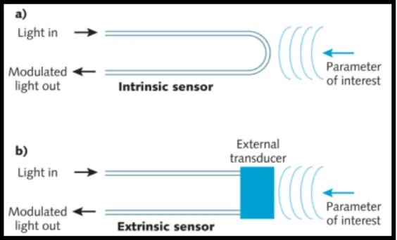
2.2.2 Fiber Optic Sensor Principles………...13
2.2.3 Case Study………14
2.2.3.1 Fiber-Optic Salinity Sensor Using Fiber-Optic Displacement Measurement with Flat and Concave Mirror……15
2.2.3.2 Fiber Optic Displacement Sensor for Temperature Measurement………...18
2.2.3.3 Fiber optic displacement sensor with a large extendable measurement range while maintaining equally high sensitivity, linearity, and accuracy………...21
2.3 Light Source……….24
2.4 Fusion Splicing...………26
2.4.1 Optical Core Alignment………...27
2.4.2 Local Injection and Detection (LID System) ………..28
CHAPTER 3: PROJECT DESIGN AND DEVELOPMENT…………..…………..…..30
3.1 Introduction………..30
3.2 Flow of Project Methodology ………..30
3.2.1 Title Finding……….32
3.2.2 Literature Review……….32
3.2.3 Deciding Raw Material……….32
3.2.4 Develop Sensor……….33
3.2.5 Testing Sensor ………..33
3.2.6 Analyse Sensor……….33
3.3 Splicing Methods………..35
3.3.1 Stripping the fiber……….35
3.3.2 Cleaning the fiber……….36
3.3.3 Cleaving the fiber……….37
3.3.4 Splicing the fiber………..38
xi
CHAPTER 4: DEVELOPMENT OF FIBER OPTIC SENSOR………...………..42
4.1 Introduction………..…43
4.2 Project Design………..…44
4.3 Measurements Results………..45
4.3.1 850nm graph results……….46
4.3.2 1550nm graph results………...49
4.4 Discussion of results……….51
CHAPTER 5: CONCLUSIONS………...………53
5.1 Introduction………..53
5.2 Discussion and conclusion for Chapter 3……….54
5.3 Discussion and conclusion for Chapter 4………..…...55
5.4 Future Work………...56
xii
LIST OF FIGURES
2.1 Model of “simple” fiber optic data link………..…5
2.2 Two distinct ways of fiber optic……….5
2.3 Diameter of single mode fiber………6
2.4 Diameter of multi-mode fiber……….7
2.5 Single-mode fiber illustration……….8
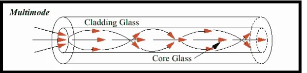
2.6 Multi-mode fiber illustration ………8
2.7 Multimode Graded Index……….…..9
2.8 Diffuse reflection of light scattering ………..10
2.9 Basic components of an optical fiber sensor system. ………..13
2.10 Extrinsic and intrinsic types of fiber optic sensors. ………..13
2.11 Variations of the output of the receiving fiber for various concentrations of NaCl in deionized water using concave mirror………..……15
2.12 Experimental setup for the proposed temperature sensor using a POF-based coupler……….……….………17
2.13 Variation of output voltage against the displacement………..19
2.14 Schematic diagram of the transmissive grating-reflective mirror based FODS system……….…….….20
2.15 Comparisons of continuous accuracy between the measured displacements by the proposed FODSs and commercial LDS from the initial movement time (4.8 s) to 50.0s………..………....22
2.16 Process of transmission light in fiber optic cable……….23
2.17 Fusion splicing illustration………...24
2.18 Automatic Fiber Alignment……….……….26
2.19 Profile Alignment Illustration.………..27
2.20 LID System Illustration process………...28
xiii
3.1 Steps of Project Methodology………..31
3.2 Flow Chart of Methodology....……….34
3.3 Stripping process………..36
3.4 Cleaning the fiber optic.cable…….………..37
3.5 Cleaving the optical fiber process………38
3.6 During fusion splicing process…….………39
3.7 After done fusion splicing process………...39
3.8 The complete developments for fiber optic sensor…….………..40
3.9 The pigtails connecter was clean up by using connecter cleaner before connect with ASE and OSA instruments…..………..41
4.1 Block Diagram of Fiber Optic Sensor Instruments………..42
4.2 Project illustration design……….43
4.3 Amplified Spontaneous Emission (ASE)……….44
4.4 Optical Spectrum Analyzer (OSA)………...44
4.5 Project Setup………….………44
4.6 The reading of voltage versus water measurement using 850nm wavelength of light source………...46
4.7 1st slope chart for 850nm wavelength of light source………….………..47
4.8 2nd slope chart for 850nm wavelength of light source……….……….47
4.9 3rd slope chart for 850nm wavelength of light source………..48
4.10 The reading of voltage versus water measurement using 1550nm wavelength of light source………...…49
4.11 1st slope chart for 1550nm wavelength of light source……….………50
4.12 2nd slope chart for 1550nm wavelength of light source………50
xiv
LIST OF TABLES
xv
LIST ABBREVIATIONS
OF = Optical Fiber
FODS = Fiber Optic Displacement Sensor
ASE = Amplified Spontaneous Emission
OSA = Optical Spectrum Analyzer
TIR = Total Internal Reflection
LED = Light Emitter Diode
POF = Plastic Optical Fiber
GAP = Graph of Displacement
TGP = Transmissive Grating Panel
NA = Numerical Aperture
OFAT = One-Factor-At-Time
NaCl = Sodium Chloride
LID = Local and Injection
1
CHAPTER 1
INTRODUCTION
1.1 Project Background
In telecommunication field, fiber optic cable is the main part of transmission of data. Fiber optic cable is used widely for communication system which is functioning for transmitting the signal or data. Besides, fiber optic also used as the sensor to detect much kind of parameters likes example humidity, temperature, concentration or water level. Another side, fiber optic communication is simple as an electrical signal that is converted to light and then transmitted through an optical fiber to a distant receiver where it is converted back into the original signal. Fiber optic has many advantages over other transmission methods. One of the advantage is a signal can be sent over longer distances without being boosted. There are also no interference problems from nearby electrical field.
2
Furthermore, in this project is focusing about Fiber Optic Displacement Sensor (FODS) that uses water as the parameter and level of water as the measurements. The FODS are more attractive because they have many advantages, such as light weight, compact size, good flexibility, electrical isolation and capability of multiplexing.
Thus, the purpose of this project is to measure the water level by using fiber optic sensor. It allows locating and detecting liquids by measuring the time delay between short light pulses entering the fiber. The sensors are placed along a standard single mode fiber cable. Although that, the fiber optic cable segments are typically connected by fusion splices. It will detect the water level whether in short, normal or overflow level. This project can be used in tunnel as to measure the water level that flow in it.
1.2 Problem statements
3
1.3 Project Objectives
Due to the problem statement above, it is cleared that the objectives of the project are:
1. To understand and study about fiber optic.
2. To develop fiber optic sensor for water level detection.
3. To analyze the performance of fiber optic sensor by using analysis technique.
1.4 Scopes of work
The scopes of work for the project include the following areas:
4
CHAPTER 2
THEORITICAL BACKGROUND
2.1 Introduction of Fiber Optic
In theory, a fiber optic is a flexible, transparent fiber that made by drawing glass (silica) or plastic to a diameter slightly thicker than of a human hair. Optical fibers are used most often as a means to transmit light between the two ends of the fiber and find wide usage in fiber-optic communications, where they permit transmission over longer distances and at higher bandwidths (data rates) than wire cables. Thus, fibers are used instead of metal wires because signals travel along them with small amounts of loss. In addition, fibers are also immune to electromagnetic interference, a problem which metal wires suffer from excessively [John M, 2009].
5
Figure 2.1: Model of “simple” fiber optic data link
There are three main parts in a model of simple fiber optic which are known as source-user pair, transmitter and receiver. In fiber optics, a source of light is used to emit electromagnetic radiation in order to perform a specific task, whether detecting faults, breaks or characterizing link-loss. While, the transmitter is transmitted the source to the receiver as well.
Figure 2.2: Two distinct ways of fiber optic
6 2.1.1 Types of Fiber Optics
There are some types of Optical Fibers such as: 1. Single Mode Fiber
2. Multimode Fiber
3. Step-index Multimode Fiber 4. Step-index Single Mode Fiber 5. Multimode Graded Index Fiber
2.1.1.1 Single Mode Fiber
Single mode fiber is one of type fiber optic. It has very thin core 9 microns in diameter. In a single mode fiber, all signal travel straight down the middle without bouncing. The advantage used single mode fibers is only one mode with one group velocity, so it had short pulse of light arrives with delay distortion. Next the rate power attenuation is lower in single mode and higher data rates to transmit. There are usually used on cable tv, internet and telephone signal. The information can send over 100km.[Chris Woodford, 2015]. Application of fiber optic typically used in long distance, higher bandwidth runs by Telecommunication, CATV companies, and Colleges and Universities.
Single-mode fibers (also called monomode fibers) are optical fibers which are designed such that they support only a single propagation mode per polarization direction for a given wavelength.
7
Single-mode guidance is important for many applications. Examples are in fiber lasers and amplifiers made of rare-earth-doped fibers, single-mode guidance is the basis for achieving a high beam quality of the output. Besides, in optical fiber communication systems, single-mode guidance avoids the problem of intermodal dispersion, which (in multimode fibers) would lead to the occurrence of multiple copies of the input signals at the receiver. Single-mode fibers are used for connecting different components in fiber-optic setups, such as interferometers. They can be fusion-spliced or put together with fiber connectors. In measurement setups, the fact is often exploited that the output of a single-mode fiber has a fixed spatial shape, independent of the launch conditions. A single-mode fiber may serve as a kind of mode cleaner. Nonlinear interactions in long single-mode fibers may be exploited. For example, this can be signal amplification via stimulated Raman scattering, or strong spectral broadening (supercontinuum generation).
2.1.1.2 Multimode Fiber
Another type is multi-mode, each optical fiber in a multi-mode cable is about 10 times bigger than one in a single-mode cable. This means light beam can travel thought the core following a verity of different paths create to ability for more data pass thorough at given time. Chris Woodford (2015). The application is typically used for short distance, the example in data and audio/video applications in LANs. RF broadband signals. Multimode fiber is usually 50/125 and 62.5/125 in construction. This means that the core to cladding diameter ratio is 50 microns to 125 microns and 62.5 microns to 125 microns.
8 2.1.1.3 Step-index Single Mode Fiber
In single mode step index has a central core that is really small so that there is potentially only one path for light ray through the cable. The light ray is propagated in the fiber through reflection in the fiber optic cable. Common core sizes are 2 until 15m. The extremely small size interconnection of cables and interfacing with source are the benefits of this type of cable.
Figure 2.5: Single-mode fiber illustration
2.1.1.4 Step-index Multi Mode Fiber
The most widely used type is multimode step index fiber. It easy to produce and its core diameter is 50 to 100 m such as large aperture and allow more light to enter the cable. There are several paths that a light ray may follow during the propagation. For example, it may propagate down the core in zig-zag manner. The principle of total internal reflection (TIR) is used to propagate the light ray. The light enters at less than critical angle is guided along the fiber because the core index of refraction is higher than the cladding index of refraction.
9 2.1.1.5 Multimode Graded Index Fiber
In fiber optics, a graded-index or gradient-index fiber is an optical fiber whose core has a refractive index that decreases with increasing radial distance from the optical axis of the fiber. Because parts of the core closer to the fiber axis have a higher refractive index than the parts near the cladding, light rays follow sinusoidal paths down the fiber. The most common refractive index profile for a graded-index fiber is very nearly parabolic. The parabolic profile results in continual refocusing of the rays in the core, and minimizes modal dispersion. Multi-mode optical fiber can be built with either graded index or step index. The advantage of the multi-mode graded index compared to the multi-mode step index is the considerable decrease in modal dispersion. Modal dispersion can be further decreased by selecting a smaller core size (less than 5-10μm) and forming a single mode step index fiber.