UNIVERSTI TEKNIKAL MALAYSIA MELAKA
FAKULTI KEJURUTERAAN ELEKTRONIK DAN KEJURUTERAAN KOMPUTER
BORANG PENGESAHAN STATUS LAPORAN PROJEK SARJANA MUDA II
Tajuk Projek : FIBER OPTIC MICROBEND SENSOR
Sesi
Pengajian : 2008/2009
Saya NIK NOZITA BINTI MOHD SAAD
mengaku membenarkan Laporan Projek Sarjana Muda ini disimpan di Perpustakaan dengan syarat-syarat kegunaan seperti berikut:
1. Laporan adalah hakmilik Universiti Teknikal Malaysia Melaka.
2. Perpustakaan dibenarkan membuat salinan untuk tujuan pengajian sahaja.
3. Perpustakaan dibenarkan membuat salinan laporan ini sebagai bahan pertukaran antara institusi
pengajian tinggi.
4. Sila tandakan ( √ ) :
SULIT*
(Mengandungi maklumat yang berdarjah keselamatan atau kepentingan Malaysia seperti yang termaktub di dalam AKTA RAHSIA RASMI 1972)
TERHAD* (Mengandungi maklumat terhad yang telah ditentukan oleh organisasi/badan di mana penyelidikan dijalankan)
TIDAK TERHAD
Disahkan oleh:
__________________________ ___________________________________
(TANDATANGAN PENULIS) (COP DAN TANDATANGAN PENYELIA)
Alamat Tetap: RKT BATU MENGKEBANG 18000 KUALA KRAI KELANTAN
ii
FIBER OPTIC MICROBEND SENSOR
NIK NOZITA MOHD SAAD
This report was submitted in partial Fulfilment of requirement for the Bachelor Degree of Electronic Engineering (Telecommunication Electronics)
Faculty of electronic and Computer Engineering Universiti Teknikal Malaysia Melaka
iii
DECLARATION
“I hereby declare that this report is result of my own effort except for works that have been cited clearly in the references.”
Signature : ……….
iv
“I hereby declare that I have read this report and in my opinion this report is sufficient in terms of scope and quality for the award of Bachelor of Electronic and
Computer Engineering (Electronic Telecommunication) with Honours”
Signature : ……….
Supervisor’s Name : EN CHAIRULSYAH B. ABDUL WASLI
v
ACKNOWLEDGEMENT
I would like to take this opportunity to express my deepest gratitude to my project supervisor; Mr. Chairulsyah b. Abdul Wasli, who has persistently and determinedly assisted me during the whole course of this project. It would have been very difficult to complete this project without the enthusiastic support, insight and advice given by him.
vi
ABSTRAK
Tujuan utama projek ini adalah untuk mencipta dan menghasilkan optic fiber
microbend sensor, untuk mengukur kuasa yang keluar, kehilangan kuasa dan analisis keputusan. Tajuk sebenar projek ini adalah fiber optic microbend sensor. Projek ini menghasilkan system pengesan yang mana termasuk punca cahaya, elemen pengesan dan pengesan cahaya. Dalam keadaan yang normal, sesetengah aras boleh dikira dan sekiranya pengesan mengesan kehadiran tekanan, paras arus akan berubah dan menunjukkan tekanan. Dalam system fiber, gelombang optic ditukarkan kepada arus elektrik dengan menggunakan pengesan cahaya. Jumlah kuasa yang dikesan oleh penerima bergantung kepada jumlah kuasa yang keluar daripada pengeluar dan dikeluarkan oleh fiber optik. Bila wayar dalam keadaan normal iaitu lurus, kuasa yang hilang sedikit berbanding dalam keaadan bengkok yang mengeluarkan banyak kuasa kerana ada cahaya yang terpantul menyebabkan kuasa pada penerima
vii
ABSTRACT
The main purpose of this project is to design and to build fiber optic microbend sensor, measure the output power, power loss and analyze the results. The title of this project is fiber optic microbend sensor. This project consists the transmitter and the receiver between the fiber optic. This project will develop a sensor system that used fiber optic cable, which is consisting of light source, sensor element and the light detector. In normal condition the certain level will measure and if the sensor senses some pressure it will change the level and indicate the level of pressure. In fiber system, the optic wave is converted into an electric current by a photodetector. The power detect at the receiver is depend on the power feed at the transmitter and the attenuation of the fiber optic. When the cable in a straight line condition, the attenuation will be minimum but if there is bend or indentation on the cable, there will be additional attenuation on the cable because some of ray light will be reflected so the power at receiver will be drop. This power differences will show that the fiber optic cable can be use as microbend sensor. This project contains calculation,
ix
II LITERATURE REVIEW 6
2.1 INTRODUCTION TO FIBER OPTIC 6
2.2 SYSTEM DESIGN CONSIDERATION 7
2.2.1 System power budget 8
2.2.2 Power at the source 8 2.2.3 Power in fiber 15 2.2.4 Power at the detector 15
2.3 CABLE CONSTRUCTION 16
2.3.1 Military standards 23
2.3.1.1 Design parameter 24
2.3.2 Fiber optic terminology 25
2.3.3 Fiber optic cost and benefits 25
2.4.6 Light Propagation on Fiber Optic 28
2.5 SINGLE MODE FIBER OPTIC 29
2.6 FIBER OFTIC MICROBEND AND
MACROBEND SENSOR 34
2.7 FIBER OPTIC MICROBEND LOSS
x
III RESEARCH METHODOLOGY 38
3.1 THEORY 38
3.2 FLOW CHART 41
3.3 TRANSMITTER CIRCUIT OPERATION 42
3.4 RECEIVER CIRCUIT OPERATION 43
xi
LIST OF FIGURE
FIGURE TITLE PAGE
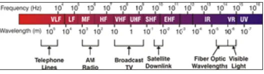
2.1 Electromagnetic Spectrum 6
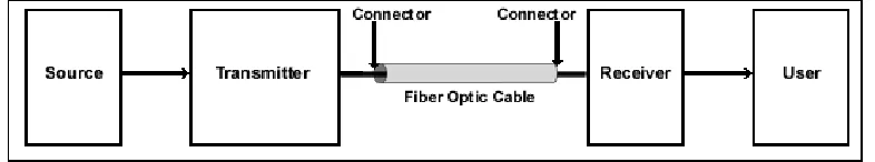
2.2 Basic fiber optic links 7
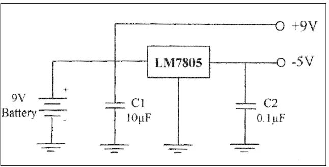
2.3 Power Supply 9
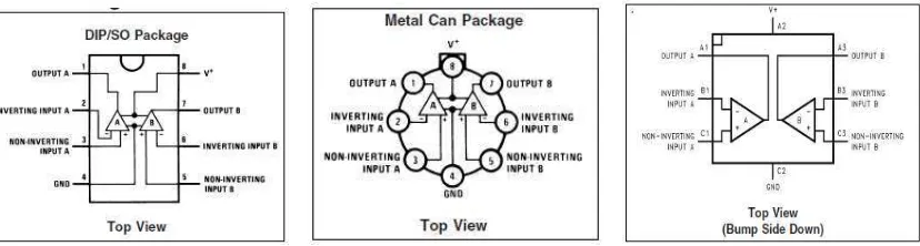
2.4 Voltage control oscillator (VCO) 10 2.5 Connection diagram 11
2.6 Transistor symbol and Schematics 11
2.7 Resistor symbols and picture 12
2.8 Potentiometer 13
2.9 Diagram voltage regulator 14 2.10 Symbol Voltage regulator 14 2.11 Fiber optic cable cross section 16 2.12 Cross section of single mode with large core diameter 17 2.13 Light propagation in single mode fiber 17 2.14 Cross section of multimode with large core diameter 18 2.15 Light propagation in step index multimode fiber 18
2.16 Light propagation in step index multimode fiber 18
2.17 Loose tube cable 19
2.18 Tight buffer cable 20
2.19 Cable construction of a plastic optic cable 21
2.20 Termini retraction and its effect on microbending 23 2.21 Basic fiber structure 27
2.22 Step index fiber 28 2.23 Numerical Aperture and Acceptance Angle 29
xii
2.25 Profile of index refraction for graded index fiber 30
2.26 Bending loss 33
2.27 Typical optical fiber 35
2.28 Microbends and macrobends 36
2.29 Fiber optic microbends 36
3.1 Project flow chart 41
3.2 Transmitter Circuit Operation 42
3.3 Receiver Circuit Operation 43
4.1 Condition of fiber optic 45
4.2 Bending radius against bending losses 46
4.3 Bending Loss 47
4.4 Block diagram for part of simulation 48
4.5 Connection for transmitter circuit simulation 49 4.6 Simulation result for transmitter circuit 50
4.7 DC analysis for transmitter circuit 50
4.8 AC analysis for transmitter circuit 51
4.9 Connection of receiver circuit simulation 52 4.10 Simulation result for receiver circuit 52
4.11 DC analysis receiver circuit 53
4.12 AC analysis receiver circuit 53
4.13 Transmitter circuit 54
4.14 Receiver Circuit 55
4.15 Waveform receiver 55
4.16 Transmitter circuit by Proteus 56
4.17 Transmitter layout 56
4.18 Receiver circuit by Proteus 57
4.19 Receiver layout 57
xiii
LIST OF TABLES
TABLE TITLE PAGE
2.1 Comparison of Optical Fiber 20
4.1 Data for each part of transmitter circuit 51 4.2 Data for each part for receiver circuit 54 4.3 Comparison output transmitter and receiver
xiv
LIST OF SYMBOL
Pi Input power
Po Output power
R Radius ℓ Length αB Bending loss
Ω Ohms
V Voltage
α
Attenuation coefficient1
CHAPTER I
INTRODUCTION
This project provides the reader with the detailed and comprehensive study of theory, design, calculation, result and problem encountered in the designing fiber optic microbend sensor. The approaches used to achieve this project are through literature review, dimensional calculation, and computer simulation. It also approaches used to analyses the characteristic and required specification before designing fiber optic microbend sensor.
Computer simulation is best technique to get the solution because it is fast and economical. The Multisim software was used to get the solution to determine its suitable parameters.
2
loss in two conditions where in normal condition and the bend condition. The suitable formula to calculate the power loss to achieved the theory.
1.1 OBJECTIVE
Most of the mechanism sensors are made of switch, which can detect huge physical touch. It is very difficult to use this sensor to detect tiny touch. The fiber optic system will act as a sensitive sensor because of its power differences when there is
bending at the fiber optic cable. The technology the fiber is widely is use and become one of the important technologies in new era. Fiber optic is one of ways to upgrade the
communication system.
The objectives of this project are;
1. To design and build fiber optic microbend sensor that able to measure the differences power loss.
2. To compare the power loss between normal and bend condition of the fiber optic.
3
1.2 SCOPE OF WORK
This project mainly focuses on the power loss from fiber optic where the system will act as a sensitive sensor because of its power differences when there is bending at the fiber optic cable. The first part of this project is to study literature. Then designing the system simulation and collecting the formula related to power loss to build the fiber optic microbend system.
From the theory, the formula power loss was found and from that, the calculation of power loss are determine where it is achieved the theory. The circuit transmitter and the receiver are designed and testing in Multisim software to determined the suitable parameters. From that, the simulations are making from the designed system. The hardware is designed and the system tested. The result were compared and analyzed.
There are six parts scope of works;
1. Study about fiber optic, power loss and transmitter and receiver circuit design. In this part, it need to find the formula to calculate the power loss, parameter of circuit and design the circuit with computer software to make sure the fiber optic microbend sensor design is perfect and success.
2. Develop the equations that related with the project to calculate the power loss in fiber optic in two conditions where normal and bend condition.
4
4. When obtain an applicable circuit from this simulation, the hardware can be started.
5. Test the hardware after the whole process is done.
6. Compare result with the expected result in simulation.
1.3 PROBLEM STATEMENT
These projects try to make the fiber optic act as a sensor and compare power loss between normal and bend condition. Fiber optic have many advantage compare where the physically small, high capacity, huge bandwidth where fiber can transmit a mind-
boggling quantity of data with extremely good transmission quantity. So that we choose the fiber optic as a sensor and it is very sensitive where can detect the small power loss in normal or bend condition.
1.4 METHODOLOGY
At the first, start planning the project with the literature review for the related journal, books and all information from internet, magazine and each other. With the all information, develop an equation to get the expected result by simulation. Try to run the simulation to look their expected result before design the hardware. If not, back to simulation once again.
5
1.5 THESIS OUTLINE
There are several outline contain in this thesis where the first one is objective of this project. To finish this project, the methodology was followed. After that, the
simulation and measurement of the result were compared and analysed. The thesis outline is shown as below:
1. Objective
CHAPTER II
LITERATURE REVIEW
This chapter will explain the basic concept and theories needed for development and implementation of the project. Besides, this chapter will provide information about fiber optic bending loss.
2.1 INTRODUCTION TO FIBER OPTIC
Fiber optic data transmission systems send information over fiber by turning electronic signals into light. The electromagnetic spectrum is composed of visible and near-infrared light like that transmitted by fiber and all other wavelengths used to transmit signals such as AM and FM radio and television. The figure 2.1 shown the electromagnetic spectrum where there is contain the frequency and the wavelength used to transmit signal [1].
7
The term wavelength refers to the wave like property of light, a characteristic shared by all forms of electromagnetic radiation. Wavelength is the measurement of the distance a single cycle of an electromagnetic wave covers as it travels through a complete cycle. Wavelengths for fiber optics are measured in nanometers [1].
Figure 2.2 Basic fiber optic links
The figure 2.2 shown the basic fiber optic link is a fiber optic system where it is similar to the copper wire systems they are rapidly replacing. The principle of this system is use light pulses (photons) to transmit data down fiber lines, instead of electronic pulses to transmit data down copper lines. Transmitter is contains with driven, source, and source to fiber connection. It essentially converts coded electrical signals into equivalently coded light pulses. At the opposite end of the fiber optic, known as the optical receiver or detector. The purpose of an optical receiver is to detect the received light incident on it and to convert it to an electrical signal containing the information overcome on the light at the transmitting end [2].
2.2 SYSTEM DESIGN CONSIDERATIONS
8
2.2.1 System power budget
A point that have consistently presented in a variety of ways throughout is the important of optical power throughput in fiber optic communications systems. The most important parameter in fiber optic communication system is the optical power transfer function. Most importantly is the output power must be greater the input sensitivity of the receiver. The system power budget is then a calculation of the power loss in each
component of the system to ensure that enough power reaches the receiver to accurately reproduce the original input information [2].
The loss in this system must be balanced with gains in order to produce a signal that is large enough in amplitude to be accurately interpreted by the receiver but not large enough cause saturation of system component. All power budgets must be major part of the system design and availability of options and the components that best satisfy both of these conditions must be considered [1].
2.2.2 Power at the source
Where the signal first enters the system, the transmitter selected must be
appropriate for the application. The type and the number of the signals are in a particular source. The LED has less power and wider line widths than laser diodes, limiting their use to shorter distances and lower data rates. These are more stable and cheaper than laser diodes [3].
A 9V battery is used as a main voltage supply to this circuits as shown in figure
9
Figure 2.3 Supply by using the Voltage Regulator
The LM358 series consists of two which is independent and high gains. It is internally frequency compensated operational amplifiers which were designed purposely to operate from a single power supply over a wide range of voltages. Operation from split power supplies is also possible and the low power supply current drain is independent of the magnitude of the power supply voltage [3].
Application areas include transducer amplifiers, dc gain blocks and all the conventional op- amp circuits which now can be more easily implemented in single power supply systems. For example, the LM358 series can be directly operated off of the standard +5V power supply voltage which is used in digital systems and will easily provide the required interface electronics without requiring the additional ±15V power supplies [6].
The Characteristic of Operational Amplifier is;
• In the linear mode the input common-mode voltage range includes ground and the
output voltage can also swing to ground, even though operated from only a single
power supply voltage.
• The unity gain cross frequency is temperature compensated.
10
The Advantages of the operational amplifier are;
• Two internally compensated op amps • Eliminates need for dual supplies
• Allows direct sensing near GND and VOUT also goes to GND
• Compatible with all forms of logic
• Power drain suitable for battery operation
Figure 2.4 Voltage Controlled Oscillator (VCO)