UNIVERSITI TEKNIKAL MALAYSIA MELAKA
INVESTIGATION OF EFFECTIVENESS AND CLEANLINESS OF
AUTOMATED BLOW FILL SEAL PROCESS IN
PHARMAUCEUTICAL INDUSTRY
Thesis submitted in accordance with the partial requirements of the Universiti Teknikal Malaysia Melaka for the
Bachelor of Manufacturing Engineering (Robotic and Automation)
By
MOHAMAD HAFIZEE BIN YAACOB
SULIT
TERHAD
TIDAK TERHAD
(Mengandungi maklumat yang berdarj ah keselamat an at au kepent ingan Malaysia yang t ermakt ub di dalam AKTA RAHSIA RASMI 1972)
(Mengandungi maklumat TERHAD yang t elah dit ent ukan oleh organisasi/ badan di mana penyelidikan dij alankan)
(TANDATANGAN PENULIS)
* Tesis dimaksudkan sebagai t esis bagi Ij azah Dokt or Falsaf ah dan Sarj ana secara penyel idikan, at au disert asi bagi pengaj ian secara kerj a kursus dan penyel idikan, at au Laporan Proj ek Sarj ana Muda (PSM). ** Jika t esis ini SULIT at au TERHAD, sil a l ampirkan surat daripada pihak berkuasa/ organisasi berkenaan
BORANG PENGESAHAN STATUS TESIS* UNIVERSITI TEKNIKAL MALAYSIA MELAKA
JUDUL: INVESTIGATION OF EFFECTIVENESS AND CLEANLINESS OF AUTOMATED BLOW FILL SEAL PROCESS IN PHARMAUTICAL INDUSTRY
SESI PENGAJIAN: 2006-2007
Saya _____________________________________________________________________
mengaku membenarkan t esis (PSM/ Sarj ana/ Dokt or Falsaf ah) ini disimpan di Perpust akaan Universit i Teknikal Malaysia Melaka (UTeM) dengan syarat -syarat kegunaan sepert i berikut :
1. Tesis adalah hak milik Universit i Teknikal Malaysia Melaka.
2. Perpust akaan Universit i Teknikal Malaysia Melaka dibenarkan membuat salinan unt uk t uj uan pengaj ian sahaj a.
3. Perpust akaan dibenarkan membuat salinan t esis ini sebagai bahan pert ukaran ant ara inst it usi pengaj ian t inggi.
4. **Sila t andakan (√)
MOHAMAD HAFIZEE BIN YAACOB
APPROVAL
This thesis submitted to the senate of UTeM and has been accepted as partial fulfillment
of the requirements for the degree of Bachelor of Manufacturing Engineering
(Robotic and Automation). The members of the supervisory committee are as follow:
……….
Supervisor
Muhammad Hafidz Fazli b Md Fauadi
Faculty of Manufacturing Engineering
DECLARATION
I hereby, declare this thesis entitled “Investigation Of Effectiveness And Cleanliness Of Blow Fill Seal Automated Process In Pharmaceutical Industry
” is the results of my own research except as cited in the reference.
Signature : ………..
Author’s Name : ………..
ABSTRACT
This thesis describes the inspection process and requirement for Blow Fill Seal
Automated for the Pharmaceutical Industry. This thesis describes the cleaning process
which consists Clean In Place (CIP) and Sterilization In Place (SIP). The processes are
Clean In Place (CIP) and Sterilization In Place (SIP). Both the cleaning process is to flush
the all particle in Piping, inlet and of the machine. For the inspection process it is very
critical for the pharmaceutical products this to be inspected effective and in short time
before being delivered. Eye inspection by human is prone error. Therefore this thesis
propose the use of machine vision to carry out the inspection tasks. The digital camera is
use to capture image of product to be analyze using vision system. Automated inspection
DEDICATION
1 dedicate this PSM thesis to my beloved parents, Khadijah Mohd Yusoff and Yaacob
ACKNOWLEDGEMENTS
Bismillahirrahmanirrahim. Alhamdullillah, with the helps and blessings from Allah
S.W.T., 1 had managed to complete this project succesfully. First of all, I would like to
thank my parents, for their concern and support, all over the time. Not forgotten my
brothers and sister, who had helps me a lot supporting me physically and morally.
I also want to thank Mr. Muhammad Hafidz Fazli Fauadi from Manufacturing
Engineering Faculty, UTeM, for supervised me all along this project, and provide helps,
guides, ideas, and suggestions to accomplish this project. All the supports and motivation
that been given to me are greatly appreciated.
Also not forgotten, Mr. Hamdan Nazeri Zainal Abidin and Mr. Rizal Mohd Nawi from
Production Department, Ain Medicare Sdn. Bhd for giving a cooperate for this case
study from beginning until finish this report.
With a deep sense of gratitude, I would also like to express my sincere thanks to my
colleague, Noorul Manan, Irwan Shah, Faizul, Hafizan and Muhammad Zhafran for the
helps and supports that been shown by them.
Finally, last but not least, thanks to all my friends who had helped me directly or
TABLE OF CONTENTS
Abstract ………..i
Dedication ……… …ii
Acknowledgement ……… iii
Table of Contents ……….iv
List of Figures ………vii
List of Tables ………..x
1. INTRODUCTION ………...1
2. LITERATURES REVIEW ………...5
2.1 Introduction ………...4
2.2 Bottle Producing Process……… ...5
2.2.1 Water Production ………....5
2.2.2 Line Process ………....8
2.3 Automation Element ……….21
2.4 Machine Vision……… ..23
2.4.1 Introduction……….23
2.4.2 Basic Component……….23
2.4.3 Working Procedure………..25
2.5 Application ……… .31
2.5.1 Inspection…… ………..24
2.5.2 Case Study For Vision System Inspection…………..………...32
3. METHODOLOGY...35
3.1 Problem Definition……….37
3.2 Choosing the Thesis Title………....38
3.3 Propose and Submit the Thesis Title………...38
3.5 Data Collection from Company……….40
4. COMPANY BACKGROUND………46
4.1 Manufacturing Facilities………..48
5. RESULT………....49
5.1 Data Collection………..49
5.1.1 Leak Bottle Head………...49
5.1.2 Dirty Body Defect.………...…..50
5.1.3 Dirty Cap Defect.………...51
5.1.4 Volume Defect.………..51 5.3 Vision System Testing Result………..67
5.3.1 Experimental Layout………..67
6. DISCUSSION………..79
6.1 Introduction ………...79
6.2 Layout Proposal For Vision System Inspection………...79
6.2.1 Effectiveness Calculation………81
6.3 Layout operation Flow Chart………...83
6.4 Image Processing……….…86
6.5 Conclusion………....86
7. CONCLISION………...87
7.1 Project Summery………...………87
7.2 Recommendation For Future Work Study………88
REFERENCE
APPENDIX A
APPENDIX B
APPENDIX C
APPENDIX D
APPENDIX E
APPENDIX F
APPENDIX G
LIST OF FIGURES
2.1 Water Treatment Flow Chart Process 5
2.2 The whole process for bottle pack line 8
2.3 Dispensing Raw Material 9
2.4 CIP Scheme of the product lines of bottle pack 13
2.5 Sterilization of the product and air system of bottle pack 14
2.6 Scheme of the sterilization path: connection bottle pack 15
2.7 Bottle Transfer 16
2.8 Mirror Welding 16
2.9 Loading Inspection 17
2.10 Sterilization and Autoclaving 17
2.11 Visual Inspection 18
2.12 Labeling Product 18
2.13 Sealing and Packaging 19
2.14 Palletizing 19
2.15 Quarantine Process 20
2.16 Delivery 21
2.17 Mandrel Die-ring 22
2.18 Raster Scan of Machine Vision System 26
2.19 The shape of object is irrelevant in array of its histogram 31
of pixel count at each gray level
2.20 A Machine Vision View the Printed Circuit Board 33
2.21 Actual Size a 100-pin gull-wing Bumpier 33
Quad Flat Pack (BQFP)
2.22 Machine Vision System close-up of 100-pin 34
2.23 Robotic Flexible Assembly 34
3.1 Project Methodology Flow Chart 37
4.1 Organization Chart 47
5.2 Dirty Body Defect 50
5.8 Bottle Miss Position after Release From BFS Machine 54
5.9 Over Air Pressure for Blowing Process 54
5.10 Dirty Body 55
5.17 January BFS Rejection Percentage 60
5.18 February BFS Rejection Monitoring Percentage 60
5.19 Conventional Visual Inspection 65
5.20 Puncher Location 65
5.27 Result of Particle Defect 73
5.28 Vision System Testing Graph 74
5.29 Grab Object Coding 76
5.30 Convert The Image To Black And White Image 76
5.31 Comparing Image 77
6.1 BFS Vision System Layout 80
6.2 The Vision System Sequences for BFS 80
6.3 Layout Distance 81
6.4 BFS Vision System Flow Chart Operation 85
LIST OF TABLES
2.1 The processes executed by BFS machines 10
5.1 Parameter of Experiment 68
5.2 Vision System Testing Result 70
CHAPTER 1
INTRODUCTION
1.0 Introduction
In the modern medical treatment, pharmaceutical solutions were the packed usually
in plastic bottle. It very safe compares with former time them usually using glass as a
packaging container or the empty plastic by using conventional filing process. Such
process required extensive precaution for manufacturing pharmaceutical sterile
product due to the difference local positioning the individual manufacturing steps,
which usually in relatively high production costs.
In the current technology, the Blow Fill Seal Process (BFS) is characterized
by the fact that the sterile plastic container production as well as the sterile filling and
closing of the container of the performed at the same place.
This technology was developed by the Germany Company called Rommelag
group since 1960s and it was already at the end of the 1960s. On 1970s when the
bottle pack Blow Fill Seal (BFS) machine were applied for pharmaceutical solution.
Start from early day, the solution used were mostly large volume products like
post-sterilized influence. However today, the Blow Fill Seal machine can produce many
type of volume, such small volume unit-dose for injection, contact lens cleaning
solution, food industry, eye drop solution and other solution.
The plastic materials for manufacturing the container offer a considerable
higher flexibility in the design of packaging compare to the glass packaging. When
round, oval, angular cross section or bellow bottle design. The flexibility also allows
mould closure design which can meet the requirement of a special product
application.
For the course time, diversification of blow fill seal machine program took
place in order to cover difference capacity needs. At the same time, the individual
components were developed further in the order to meet the increasing requirement
of the clients and authorities of the pharmaceutical sector.
The Blow Fill Seal machines normally operate after water preparation,
product preparation and sterile filtration. The filling product is fed in sterile condition
to the bottle pack blow fill seal machine. The plastic granulate is transported from the
resin material storage to the blow fill seal machine. This processed there to plastic
packaging, filled with the filling product and sealed immediately.
The essential components of the blow fill seal machines themselves are a
resin-extrusion equipment and container molding system with the integrated dosing
process as well as separated cabinet modules where motors, pump, ventilator, valves,
and electrical installation to control the machine.
The blow fill seal process start with the forming of the plastic container.
Usually they use the low, medium and high density polyethylene as well as melted,
homogenized and extruded as plasticized parisons. In the blow process, the extruder
parisons are molded as container in the mold. After that, they are filled immediately
at the same position by dosing needles with the requested filling quantity. After
completion of dosing, the filling mandrels rise vertically to their upper rest position
and special closing tools weld the container hermetically, where the requested
closure is welded by vacuum. After that the entire mold opens and the container is
discharged the cycle begins again. The duration time to complete this process is
In the pharmaceutical industry, the Blow Fill Seal product called Intravenous
Solution (IV Drips). The IV Drips function is to supply of nutrition with or without
medicine direct into the blood stream of the patient. This solution must be clean from
any contamination, sterile from any microorganism and non-pyrogenic substance and
temper bottle. The nutrition content can be one or a mixture of carbohydrate, mineral
salts, protein, fats and vitamins which are needed daily for patient’s survival. The
nutrition in IV drips is in the simplest form and can be absorbed by the human body
direct without with other process. This solution administered intravenously cannot be
removed from the patient by any mechanical or other means. In medical field, IV
drips is very importance because patients need nutrition daily to survive, recover and
recuperate their body. They also cannot and drink by usual means. They must used
this IV Drips to produce energy to survive. The IV Drips is a vehicle for antibiotic
and medicine treatment to treat the patient ailment.
The manufacturer must have relevant license certificate from National
Pharmaceutical Control Biro (NPCB) from Malaysia Ministry of Health. The issued
must issue by Malaysia Ministry of Health Director. Their certificate must renew for
annually. Manufacturer must conform to the requirement for good practice in the
manufacture and quality control as recommended by World Health Organization
(WHO) and the Malaysian guideline on Good Manufacturing Practice. If any
manufacturer not fulfills the Malaysian guideline or their product fails such as not
sterile, pyrogenic, wrong labeling, wrong concentration and Good Manufacturing
CHAPTER 2
LITERATURE REVIEW
2.1 Introduction
When we look at the plastic bottle, can we think how to produce that bottle?
What the material they used? For this project we want to describe how to make it?,
what the machine they used? What the automation element at the machine?.
Basically, the plastic bottle produce by lower density plastic (LDPE). The main
industry used this bottle is the pharmaceutical industry and food industry.
For this thesis we want to describe effectiveness and cleanliness of blow fill
seal (BFS) technology in pharmaceutical industry. In pharmaceutical industry the
cleanliness is very important to use it because it must sterile process to avoid any
contaminations and sterile from microorganisms in the product.
The automation element also we discuss in this thesis. We can research about
the automation to support the product produce. This thesis also can discuss about the
2.2 Bottle Producing Process
2.2.1 Water Production
The bottle pack line process beginning with water treatment process. In this
process it involves their water producing for mixing with raw material at line mixing
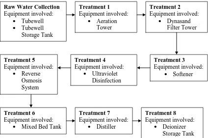
room. The flow chart process shown in figure 2.1:-
Figure 2.1: Water Treatment Flow Chart Process
2.2.1.1 Raw Water Collection
It function is sucking up water from the ground (ground water) to the
Tubewell tank. It used one pump to operate this process. All water after
sucking keeping in storage tank to avoid for any contaminations and chemical
reaction. The tubewell capable to suck water 30m3/hour or 720m3/day. The
capacity of is 3500L/ period. Equipment involved are Tubewells and
Tubewell Storage Tank.
2.2.1.2 Treatment 1
The process of this treatment is to carry the water and air combining to
remove Ferum (Fe) and Mangan (Mn). In this process, Ferum (Fe3+) curve to
produce ferum Hidrokside [Fe(OH)3] at packing tower. This process very
importance because to increase the O2 dissolved. For remove Hydrogen
Sulfur (H2S) gas and carbon Monoxide (C2). Equipment involved is Aeration
Tower. The tower capacities are:-
- Input = 30m3/hour
- Output = 30m3/hour
- Total supply = 720m3/day
2.2.1.3Treatment 2
Dyanasand Filter function is to filter and remove Suspended Particle in raw
water. This process is very important because to avoid their water from
microorganisms contaminations. Equipment involved is Dynasand Filter
.The Dynasand Filter capacities are:-
- Input = 30m3/hour
- Output = 27m3/hour
- Total supply = 648m3/day
2.2.1.4Treatment 3
After raw water filter at the Dynasand Filter, the function of softener is to
mixing with raw water they move to the softener to softening process with
ion changing in the raw water with Natrium (Na+) supply by softener tank.
The main function of softener is to remove the bad particle from the raw
water. Equipment involved is Softener. The capacities of Softener are:
- Input = 4m3/hour
2.2.1.5Treatment 4
To make sure a microorganism free, UV Disinfection using UV radiation to
activate the microorganism in the water the free the water from bad
microorganism. It can supply 12 000 l/day. Equipment involved is Ultra
Violet (UV) Disinfection.
2.2.1.6Treatment 5
In this part were using membrane separation processes. This process is
removing impurities with semi permeable membrane to produce Reverse
Osmosis (RO) water. This water also call mineral water and properly to
drink. The equipment involved is Reverse Osmosis System.
2.2.1.7Treatment 6
In the Mixing Bed Deionizer, the processes operate to change positive ions
and negative ions in the RO water with hydrogen supply by resin. The water
in this system called Purified Water. Equipment involved Mixing Bed
Deionizer
2.2.1.8Treatment 7
The distiller function is to deionizer the water with heating process for
deionizer water in Evaporator Column with raw steam supplying from Boiler
2.2.1.8 Treatment 8
The function of this tank is to store the distillate water before mixing process
with their raw material. The capacity of this tank is 20000L/tank in 800C.
Equipment involved is Deionizer Storage tank.
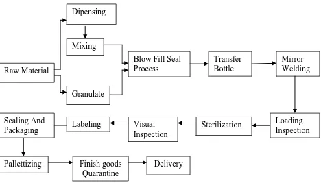
2.2.2 Line Process
After water treatment process complete, Water in Deionizer Storage Tank must flow
to the mixing tank before mix with raw material. The block diagram following figure
2.2:-
Figure 2.2: The whole process for bottle pack line
2.2.2.1 Raw Material
Raw Material can categories for the two types, first category is bottle pack
material. The material using is LDPE for producing bottle. Second category
is water solution raw material. The raw material will be mix with deionizer
water in mixing tank. All raw materials coming from raw material warehouse. Dipensing
Pallettizing Finish goods Quarantine
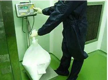
2.2.2.2 Dispensing
Figure 2.3 shown the Dispensing Process to produce the water solution.
Dispensing mean weighing process. The weighing process is to weight
their raw material for the water solution. [ European Pharmacopoeia
Commission 2005 ]
Figure 2.3: Dispensing Raw Material
2.2.2.3 Granulate Tank
The granulate tank which is a storage for bottlepack material. This tank
connected with BFS machine. When the BFS machine operate, the machine
suck with in a one tube to the material hope at the machine. [ European
Pharmacopoeia Commission 2005 ]
2.2.2.4 Blow Fill Seal Process
BFS machine is the main part for the bottlepack process. It is place where the
raw material for water solution and bottle producing will be combining. Table
2.1 show the processes executed by BFS machines. [Dr. R. Oschman, Dr.
Willmar Schwabe Gmbh, D-Karlsruhe, Germany, Dr. O.E. Schubert,
Table 2.1: The processes executed by BFS machines
Figure For Step Process Description
Step 1 Extrusion
• The transparent polyethylene containers of medium density allow a post a post-sterilization of up to approximately
1100C.
• In the extrusion system, the resin is heated up to 1700 C-2300C, whereas pressure of up to 350 bar exist. The
container result in the sterility of the resin which is
discharged as parisons. In various challenge tests in which
bacterial inoculated resin contamination with the
endotoxines were used, no growth of germs was discovered
after evaluation and no endotoxines was proven to be in the
plastic granulate are surrounded by the plastic melt and
therefore cannot migrate from the packing into the product
Step 2 Molding
• When the parison is taken over by the mold, it is separated by an incandescent cutting knife below the extrusion die and
within a second the mold with the parison move to the filling
position. Sterile air with which the parison was kept under
pressure escape at the upper opening of the parison and
avoids the surrounding air entering into the parison and the
sterility within the parison is kept.
• The mold has reached the blowing/filling position, the combined blowing/filling mandrel moves from the upper rest
position into the open parison. The parison is then blown up
with sterile air and is pressed against the mold wall.
The machine preparation, the blowing and filling mandrel
are sterilized. Except during the blowing and filling. The
combined blowing and filling mandrel are the upper rest