UNIVERSITI TEKNIKAL MALAYSIA MELAKA
A STUDY ON 3D MODELING TECHNIQUE
Thesis submitted in accordance with the partial requirements of the Universiti Teknikal Malaysia Melaka for the Bachelor of Manufacturing Engineering
(Manufacturing Design)
By
SYARIFAH MAHANI BT MOHD NAZRI
Metric Number: B050410104
UTeM Library (Pind.1/2007)
UNIVERSITI TEKNIKAL MALAYSIA MELAKA
BORANG PENGESAHAN STATUS LAPORAN PSM
JUDUL:
A STUDY ON 3D MODELING TECHNIQUE
SESI PENGAJIAN: Semester 2 2007/2008
Saya SYARIFAH MAHANI BT MOHD NAZRI
mengaku membenarkan laporan PSM / tesis (Sarjana/Doktor Falsafah) ini disimpan di Perpustakaan Universiti Teknikal Malaysia Melaka (UTeM) dengan syarat-syarat
kegunaan seperti berikut:
1. Laporan PSM / tesis adalah hak milik Universiti Teknikal Malaysia Melaka dan penulis.
2. Perpustakaan Universiti Teknikal Malaysia Melaka dibenarkan membuat salinan untuk tujuan pengajian sahaja dengan izin penulis.
3. Perpustakaan dibenarkan membuat salinan laporan PSM / tesis ini sebagai bahan pertukaran antara institusi pengajian tinggi.
4. *Sila tandakan (√)
SULIT
TERHAD
TIDAK TERHAD
(Mengandungi maklumat yang berdarjah keselamatan atau
kepentingan Malaysia yang termaktub di dalam AKTA RAHSIA RASMI 1972)
(Mengandungi maklumat TERHAD yang telah ditentukan oleh organisasi/badan di mana penyelidikan dijalankan)
(TANDATANGAN PENULIS) Alamat Tetap:
Rumah Guru Sek. Men. Teknik 02600 Arau Perlis
Tarikh: _______________________
(TANDATANGAN PENYELIA)
Cop Rasmi:
Tarikh: _______________________
D
ECLARATION
I hereby, declare this thesis entitled “A Study On 3D Modeling Technique”. All the result
and analysis of my own research except as cited in the reference.
Signature :
Author”s Name : Syarifah Mahani Bt Mohd Nazri
APPROVAL
This thesis submitted to the senate UTeM and has been accepted as fulfillment of the
requirement for the degree of Bachelor of Manufacturing Engineering (Manufacturing
Design). The members of supervisory committee are as follows:
……….
Supervisor
(Mr. Shajahan B. Maidin )
ABSTRACT
Research that carried out inside this project is all about 3D modeling technique. This
project is involving the research of numerous techniques that being used by student in
order to produce 2D shape to 3D model. There are a lot of advantages of CAD
(Computer Aided Design) discovered such as plan view, side view and front view can
easily being generated. Beside that, the generated 3D model can also useful for other
automated process such as CAM (Computer Aided Machining) as well as CAE
(Computer Aided Engineering). This project is also important in finding factors that
affected the 3D modeling skills of UTeM students. The weaknesses of the students have
been discovered and the best method for producing the effective 3D modeling
techniques has also being introduced. All the problems were identified by performing
several tests and questionnaire to the students. The result obtained from this project has
let us know the level of skills for the undergraduate students and some suggestion and
recommendation for further improvements had been introduced.
ABSTRAK
Kajian yang dijalankan di dalam tesis ini adalah berkenaan teknik permodelan 3
dimensi. Projek ini melibatkan kajian terhadap teknik-teknik yang digunakan oleh para
pelajar dalam menghasilkan bentuk-bentuk dari 2 dimensi sehinggalah ke bentuk 3
dimensi. Disini didapati bahawa terdapat banyak kelebihan dalam CAD dimana setiap
pandangan pada sesuatu objek 3 dimensi dapat diperolehi serentak (pandangan atas,
pandangan sisi dan pandangan hadapan). Disamping itu model 3 dimensi yang terhasil
dapat digunakan terus untuk proses-proses lain seperti CAM (Permesinan terbantu
computer) dan CAE (Analisis Kejuruteraan Terbantu Komputer). Projek ini adalah
penting bagi mengkaji factor-faktor yang mempengaruhi teknik permodelan 3 dimensi
bagi pelajar UTeM. Projek ini dapat mengenalpasti kelemahan-kelemahan pelajar dalam
proses permodelan bentuk 3 dimensi dan seterusnya memperkenalkan kaedah terbaik
bagi menghasilkan teknik permodelan yang efektif. Permasalahan-permasalahan ini
telah dikenalpasti melalui ujian-ujian serta borang kaji selidik yang telah dijawab oleh
para pelajar. Hasil yang diperolehi daripada projek ini telah mendedahkah tahap
kemahiran pelajar dan cadangan untuk penambahbaikan telah diperkenalkan.
DEDICATION
For my beloved father, mother and family and also to my friends
especially to Mr. Mohd Izhar Bin Harun
ACKNOWLEDGEMENTS
I would like to thank to Allah S.W.T for giving me strength and health to complete this
project. I also would like to express my gratitude to Mr. Shajahan Bin Maidin for his
supervision for the support and suggestion and also his explanation to understand and to
carry out the project. His guidance, comment and help had improved me in the project.
His advice, willingness and encouragement are inestimable.
I also would like to express my sincere thanks to the all final year students which
commit to answer the questionnaire especially to all my friends that had come to help
me during data collection time. A lot of thanks also to my beloved roommate Ms Noor
Aswani Bt Sulaiman for her sincere help to complete this project.
.
TABLE OF CONTENT
1.5 Importance of the project 4 1.6 Organization of the report 4
1.7 Gantt chart 5
CHAPTER 2: LITERATURE REVIEW
2.1 History of CAD 7
2.2 Introduction to modeling tool 8 2.2.1 Solid modeling 10 2.2.2 Parametric modeling 11 2.3 Introduction of 3D model 12 2.4 Introduction to CATIA 13 2.4.1 Basic CATIA features 15 2.5 Current 3D Modeling 16 2.6 Improvement in 3D Modeling 16 2.7 Software comparison 17
CHAPTER 3: METHODOLOGY
3.1 Introduction 18
3.2 Product tree structure 18
3.3 Flow chart 19
3.3.1 Gaining information 20 3.3.2 Plan for data collection 20 3.3.3 Set for design sketch 20 3.3.4 Software selection 21
5.2 Result from sketcher test 26 5.2.1 Method chosen by student 28 5.2.2 Factors that influence the chosen starting point 29 5.2.3 Drawing time based on gender 30 5.2.4 Software familiarization 32 5.3 Result from modeling test 33 5.3.1 Time for student to complete modeling process 39 5.3.2 Gender factor 39 5.3.3 Software familiarization 42 5.3.4 Problem occur in modeling 44 5.4 Questionnaire result 47
CHAPTER 6: DISCUSSION
6.1 Drawing selection 61 6.2 Software selection 63 6.3 Analysis for sketcher test 64 6.4 Analysis for the modeling test 65 6.5 Analyze the types of tool 66 6.6 Factors that affected the modeling techniques 66
CHAPTER 7: SUGGESTION AND RECOMMENDATION 71
CHAPTER 8: CONCLUSION 80
REFFERENCE
APPENDIX
LIST OF FIGURE
2.4.1 Modeling using CATIA 12
3.2.1 Product tree structure 17
3.3 Flow chart 18
5.2.1 Drawing that used in sketching 24
5.2.1.1 Choosing Drawing with numbering method 25
5.2.2.1 Starting point factor 27
5.2.3.1 Time taken by male student 28
5.2.3.2 Time taken by female student 29
5.2.4.2 Time taken based on software rate 29
5.3.1 Gas holder drawing 30
5.3.2 Page 2 gas holder drawing 32
5.3.3 Door knob drawing 34
5.3.4 Final model for gas holder 35
5.3.5 Final model for door knob 35
5.3.1.1 Bar chart for overall draw time for all student 36
5.3.2.1 Bar chart for time taken by male students 37
5.3.2.2 Bar chart for time taken by female students 38
5.3.2.3 Gender comparison based on time taken to complete model 39
5.3.3.2 Time taken based on software familiarization 40
5.3.4.1 The percentage of student based on problem occur 42
5.3.4.2 Four steps for modeling technique 43
5.4.1 Bar chart for question 1 45
5.4.2 Bar chart for question 2 46
5.4.3 Bar chart for question 3 47
5.4.4 Bar chart for question 4 48
5.4.5 Bar chart for question 5 49
5.4.6 Bar chart for question 6 50
5.4.7 Bar chart for question 7 51
5.4.8 Bar chart for question 8 52
5.4.9 Bar chart for question 9 53
5.4.10 Bar chart for question 10 54
5.4.11 Bar chart for question 11 55
5.4.12 Pie chart for question 12 56
5.4.13 Bar chart for question 13 57
6.1.1 Drawing for sketching process 58
6.1.2 Drawing for modeling process 59
6.6.1 Sketch been made and pad command to create first cylinder 64
6.6.2 Sketch been made and pad command to create second cylinder 65
6.6.3 Sketch half cross section of the part being made 65
6.6.4 Shaft command being used to create cylinder 1 and 2 66
7.1 Planning flow chart 70
7.2 step 1 71
7.3 step 2 72
7.4 step 3 72
7.5 step 4 73
7.6 step 5 73
7.7 step 6 74
7.8 step 7 74
7.9 step 8 75
7.10 step 9 75
7.11 step 10 76
1.6.1 Gantt Chart PSM 1Gantt Chart P 5
1.6.2 Gantt Chart PSM 2 6
2.1 Typical software 10
Number of student and time taken to complete drawing via method chosen
25
5.2.2. 1
Factor influence the starting point 26
5.2.3. 1
Gender comparison 28
5.2.4. 1
Time taken based on software use rate 29
5.3.2. 1
No. of student based on time taken 37
5.3.2. 2
Time taken by female student during drawn session 38
5.3.3. 1
Time taken for student based on software familiarization 40
5.3.4. 1
Problem occur in modeling 41
5.4.1 Table for question 1 44
5.4.2 Table for question 2 45
5.4.3 Table for question 3 46
5.4.4 Table for question 4 47 5.4.5 Table for question 5 48 5.4.6 Table for question 6 49 5.4.7 Table for question 7 50 5.4.8 Table for question 8 51 5.4.9 Table for question 9 52 5.4.10 Table for question 10 53 5.4.11 Table for question 11 54 5.4.12 Table for question 12 55 5.4.13 Table for question 13 56
X
LIST OF ABBREVIATIONS
CAD - Computer Aided Design
CATIA - Computer Aided Three dimensional Interactive Application
2D - 2 Dimensional
3D - 3Dimensional
CAM - Computer Aided Manufacturing
CAE - Computer Aided Engineering
Pro-E - Pro/Engineer
CHAPTER 1
INTRODUCTION
1.1 BACKGROUND
Manufacturing Engineering Faculty is one of the several faculties in UTeM. This
faculty has five main programmed such as Manufacturing Design, Manufacturing
Process and System, Robotic and Automation, Engineering Material and the last one
is Manufacturing Management.
Manufacturing Design course focuses on design and manufacturing processes by
using modern CAD tools as well as can. Students with strong manufacturing
engineering background will be further exposed to techniques and approaches in
design for manufacturing and assembly. The skills will help them in designing
products and cost-effective system with high quality as well as environmentally safe.
All student in this course had exposed to the design field since they are in year one.
They had to take Graphic Engineering and CAD subject in year one then to improve
their skill and the ability to be a creative person. UTeM also has offered several
subjects that need student to create a new design or improve any existing design to
fulfill the requirement for that subject.
CAD is a short form for Computer-Aided Design [1]. It is a technology concerned
with the use of computer system to perform certain functions in design and
production. This technology is moving in the direction of greater integration of
design and manufacturing. Ultimately, CAD will provide the technology base for the
computer-integrated factory in the future.
All UTeM students will learn about basic CAD which is AutoCAD in year one. After
that, for Design student they will continue to be taught advance CAD software which
is Solidworks in year two and lastly CATIA software in year four. AutoCAD is a 2D
drawing and CATIA or Solidworks software is for 3D drawing. However nowadays
AutoCAD software has been upgraded with 3D features.
2D or 2 Dimensional drawing is the drawing that only be drawn on top of a plane
which is in 2 axis. 3D drawing is the drawing that exist in 3 axis and the fully object
can be seen in 3D mode by using isometric view. The advantages of generating 3D
drawing is students or designer can save their time in designing process where plan,
front and side view can be obtained in the same time.
People that involve in designing will familiar with acquiring information from
three-dimensional (3D) shape objects. This information will be transmitted more rapidly
and more efficiently by using visual expression of the objects to be presented. In
order to visualize some information in computer system, internal representation or in
other word is modeling would be added to make it easily manipulated by computer.
Solid modeling is actually describing 3D geometry and topology of an object in
computer system. This refers to an internal representation of an object in 3D space.
The operating involved are insertion, deletion and modification on an object [19].
This project intends to use CAD system to access and discover student’s 3D
modeling technique so that improvement on their designing and modeling abilities
can be addressed. An exercise will be provided and their modeling technique will be
attained. It’s also trying to identify any related issues that influenced the designing
complexity and conclude the results in a contingency model which can be used by
others students in designing.
1.2 PROBLEM STATEMENT
The area of this project is about the capability of the final year design student in
designing by using CAD software. The ability of the students to respond quickly and
effectively to design and technical changes rests on students being competent in the
procedure of utilizing computer aided systems efficiently. Students exposed to the
present day computer-based graphics are exercising various techniques and
principles for solving 3D modeling or designing problems. This defiance in applying
various basic principles and techniques of 3D mechanical modeling needs to be
addressed. Better and systematic modeling strategies serve to reduce time of
designing. The aim of this study was to investigate the extent to which
Manufacturing Design Engineering program students acquire and retain 3D modeling
strategy following a 3D modeling course. An exercise for designing a 3D model will
be used and assessment on their modeling strategy will be made.
1.3 OBJECTIVE
1. To study and analyze the 3D modeling techniques and skill of students
2. To study and analyze the types of tools used in 3D modeling
3. To study factors that affected the modeling techniques
4. To develop and propose a contingency model for 3D modeling technique
1.4 SCOPE
This report entitled A Study On 3D Modeling Technique will use CAD software to
accomplish this project. It focuses on 4th year design student in their skill in 3D
modeling technique. This project is about how the student model part given by using
CAD software. It starts with the sketching in 2D and then continues with the 3D
parametric modeling. Then it will come out with the comparison on the design
process, the method they used and also to propose a best way for modeling technique
in design.
1.5 IMPORTANCE OF THE PROJECT
The importance or the key point of the project is about a 3D modeling technique for
design students. This project needs to find out the capability of student in design and
also their modeling skill. Identify which methods are easier for student to draw and
also studied about the common method that use by student in designing process. All
the data collected will be used for analysis to develop and propose the best method in
designing. It may reduce design process time and also to improve the quality and
productivity of design students.
1.6 ORGANISATION OF THE REPORT
In chapter one it will consist manufacturing engineering faculty background. The
course provides and the focus in this chapter is on the Manufacturing Design course.
In this chapter also have the explanation about the term of CAD/CAM, the problem
statement of the research and the objective of this case study. To make it clearly it
also contains the boarder or the limitation of the research and also the meaning of the
research title.
Chapter two will cover the literature review of the report. It consist the previous
research or article that relevant with this research. It also provides all the definition
or function of the method that use in the research.
Chapter three is the methodology. This chapter will cover about the way that will
chosen and use in the research. The other sides are the explanation of how to solve
the problem and what method that use to help or to show the result.
Chapter four is the testing method. This chapter will cover about the testing that had
used in this project. There are about two test and one questionnaire session that had
been used to obtain the result.
Chapter five is the result from this project. This chapter will cover the analysis from
testing method and questionnaire session.
Chapter six is the discussion. It will discuss the result and the analysis that had been
obtained in the chapter five.
Chapter seven is the suggestion and recommendation to improve the findings of this
project in the future. Chapter eight is the conclusion for the whole project.
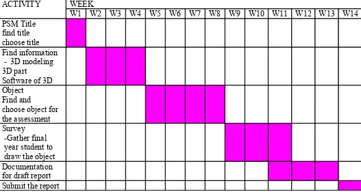
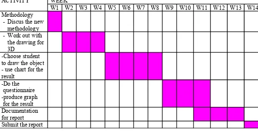
Table 1.6.1 and table 1.6.2 below is the Gantt chart for the PSM 1 and PSM 2. Both
Gantt chart are about the planning that will be done in the project, it also contain the
aimed time to complete the plan.
Table 1.6.1: Gantt chart PSM 1
Table 1.6.2: Gantt chart PSM 2
ACTIVITY WEEK
W1 W2 W3 W4 W5 W6 W7 W8 W9 W10 W11 W12 W13 W14
Methodology - Discus the new
methodology - Work out with
the drawing for 3D
-Choose student to draw the object - use chart for the result
-Do the questionnaire -produce graph
for the result Documentation for report Submit the report
CHAPTER
2
LITERATURE REVIEW
2.1 HISTORY OF CAD
In the late 1970s, the pressure to introduce product to the market in a faster way
became more demanding and the desire to reduce lead times led to the discovery of
Design for Manufacture (DFM). At the early stage of DFM implementation in
manufacturing industry, Manufacturing Engineer were involve from the beginning in
the design phase by giving suggestion to improve manufacturability, then it followed
by the designer that was trained to have awareness on manufacturability aspects
during the design process. A guideline was produced to assist designer in the design
phase to produce design that can be manufactured without any manufacturability
problems. When the computer technology became more advance, CAD tools was
introduced into manufacturing industry to help designer to design product easily and
this help to increase productivity and reduce time consuming in the design iteration
itself [9].
Three-dimensional models are one of the terms in CAD. It is increasingly used in
various areas of manufacturing, research and education. Mechanical parts represent
an important fraction of various products widely used in our society. Fierce
competition demands a permanent increase in productivity and faster response to
design and technical change on products. This has led to widespread use of computer
aided design software. Students exposed to the present day computer-based graphics
modeling are exercising various techniques and principles for solving 3D mechanical
modeling so better and systematic modeling strategies needs to be addressed to
reduce time of designing [6].
2.2 INTRODUCTION TO MODELING TOOLS
25 years ago, nearly every drawing produced in the world was done with pencil or
ink on paper. Minor changes meant erasing and redrawing while major changes often
meant recreating the drawing from the scratch. If a change to one drawing affected
other documents you were dependent upon having someone manually recognize the
need to make the changes to the other drawings and to do so. CAD has
fundamentally changed the way design is done [10].
CAD or computer-aided design is a combination system of hardware and software
that enables engineers and architects to design everything from furniture to airplanes.
In addition to the software, CAD systems require a high-quality graphics monitor; a
mouse, keyboard, or digitizing tablet for drawing; and a special printer or plotter for
printing design specifications [1].
CAD systems allow an engineer to view a design from any angle with the push of a
button and to zoom in or out for close-ups and long-distance views. In addition, the
computer keeps track of design dependencies so that when the engineer changes one
value, all other values that depend on it are automatically changed accordingly.
Until the mid 1980s, all CAD systems were specially constructed computers [2].
In Computer Aided Design (CAD), Solid model of the product needs to be created.
Parametric based solid model is an ideal basis for conducting design. The basic role
of CAD is to precisely define the geometry of a design where it is critical to all
subsequent activities in the product cycle development. Solid modeling has focused
on modeling objects to capture their shape or geometry inclusive of related
topological aspects. Solid modeling has been used in mechanical engineering, design
analysis and manufacturing where the geometry information present in the solid
models is utilized and processed for various proposes as an example to compute
material characteristic and performance parameters in CAE application [8].
The rapid development of CAD has become the driving force for research and
development in Concurrent Engineering is to develop an intelligent CAD system, the
task is performed by Automated Manufacturability Analysis. Automated
Manufacturability Analysis is a process which involves analyzing the design for
potential manufacturability problems and assessing its manufacturing cost [9].
Listed below are the advantages of CAD [10].
· Precise
designing products and facilitate direct and indirect manufacturing by creating actual
parts directly from digital input. These solutions are used for design communication
and prototyping as well as for production of functional end-use parts [12]. Table
2.2.1 below is some of the typical CAD/CAM/CAE software. It contains the software
and the system that use in CAD/CAM/CAE.