UNIVERSITI TEKNIKAL MALAYSIA MELAKA
Intelligent Vehicle Parking System of all shopping complex in
Malaysia with Radio Frequency Identification (RFID)
This report submitted in accordance with requirement of the Universiti Teknikal Malaysia Melaka (UTeM) for the Bachelor’s Degree in Electrical Engineering
Technology (Electronic Industry) (Hons.)
By
Menzi Lee Meng Zhen B071210001 920203-07-5048
DECLARATION
I hereby, declared this report entitled “PSM Title” is the results of my own research except as cited in references.
Signature :………
Name : ………
APPROVAL
This report is submitted to the Faculty of Engineering Technology of UTeM as a partial fulfillment of the requirements for the degree of Bachelor of Engineering Technology Industrial Electronic (Hons.). The member of the supervisory is as follow:
ABSTRACT
v
ABSTRAK
vi
DEDICATIONS
vii
ACKNOWLEDGEMENT
I would like to thank all my lecturers, coursemates and individuals who had supported and encouraged me in this project First, I would like to express my gratitude towards Mr. IR Nik Azran Bin AB Hadifor the guidance and advices throughout the process of completing this project. Besides that, I would also like to thank my academic advisor Mr TG Mohd Faisal Bin Tengku Wook for assisting and providing support for me in this project.
viii
CHAPTER 1: INTRODUCTION ... 15
1.0 Introduction ... 15
1.1 Background ... 15
1.1.1 Vehicle’s parking system of Shopping Complexes in Malaysia ... 15
1.1.2 History of RFID ... 16
1.1.3 Concept of RFID ... 17
1.1.4 Automatic Identification system ... 17
1.2 Problem Statement ... 18
1.3 Objectives of Project ... 18
1.4 Scope of project ... 19
1.5 Project Limitation ... 20
CHAPTER 2: LITERATURE REVIEW ... 21
2.0 Introduction ... 21
ix
2.1.1 RFID tag ... 22
2.1.2 RFID reader ... 25
2.2 Communication between RFID reader and tags ... 27
2.3 Electronic product codes ... 29
2.4 The industrial, scientific and medical (ISM) radio bands ... 30
2.5 RFID Security ... 30
2.6 Data Storage in RFID and comparison with Barcodes ... 31
2.7 Speed of reading and error rate ... 32
2.8 Contactless payment using smart cards ... 33
2.9 Implementation of RFID technology in vehicle parking system ... 34
2.10 Electronic Toll Payment System ... 35
CHAPTER 3: METHODOLOGY ... 37
3.0 Introduction ... 37
3.2.5 Liquid-Crystal Display (LCD) ... 43
3.2.6 ISP-USP flash programmer ... 44
3.2.7 Universal Asynchronous Receiver/Transmitter(UART) ... 44
3.2.8 Piezo buzzer ... 45
3.2.9 Infrared Sensor (IR) ... 46
x
3.3.1 Proteus Design Suite ... 47
3.3.2 C Programming ... 47
3.3.3 Hyper Terminal ... 48
CHAPTER 4: RESULT & DISCUSSION ... 49
4.0 Introduction ... 49
4.1 Range of 125kHz RFID’s Reader ID-20LA ... 49
4.1.1 Comparison of Expected Reading and Actual Reading of 125 kHz Reader 51 4.2 Detection of the RFID Card with the Reader in Presence of Obstacle ... 52
4.2.1 Thickness of Obstacle with the Maximum Range of RFID Reader ... 52
4.2.2 Material of obstacle with the detection of RFID card ... 54
4.2.3 Multiple RFID cards testing ... 56
4.3 Analysis of Frequency Waveforms of RFID’s Reader ... 57
4.3.1 The Frequency when RFID Reader ID-20LA Detect the Card ... 57
4.4 Coding Result for Stimulation Serial interfacing ... 59
4.4.1 Serial Initialization ... 59
4.5 The Stimulation circuit in Protues ... 60
4.5.1 Entry part of the system ... 61
4.5.2 Exit part of the system ... 64
4.5.3 Security and monitoring system of the car park system ... 66
4.6 Hardware ... 68
4.6.1 PCB layout design ... 68
4.6.2 Project prototype ... 70
4.7 Discussion ... 72
4.7.1 Vehicle parking payment system ... 72
4.7.2 Characteristic of the RFID reader... 72
xi
4.7.4 Hardware ... 74
CHAPTER 5: CONCLUSION AND RECOMMENDATION ... 76
5.0 Introduction ... 76
5.1 Summary ... 76
5.2 Achievement of Objectives ... 76
5.3 Significant building of this system ... 77
5.4 Problem faced ... 77
5.5 Recommendation ... 77
APPENDIX A ………..………80
APPENDIX B……….81
xii
LIST OF TABLES
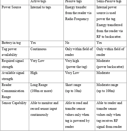
Table 2.1 RFID tags comparison ... 24
Table 2.2 Frequencies and read range of RFID system... 27
Table 2.3 Comparison between the 125 kHz and 13.56 MHz RFID technology ... 28
Table 2.4 EPC class with respective RFID tags ... 29
Table 4.1 Read Range of 125 kHz RFID’s Reader ... 51
Table 4.2 Expected Reading and Actual Reading of 125 kHz Reader ... 51
Table 4.3 Thickness of books with maximum read range ... 53
Table 4.4 Different Materials of Obstacle with the Maximum Read Range ... 55
Table 4.5 Number of RFID Cards with Detection ... 56
xiii
LIST OF FIGURES
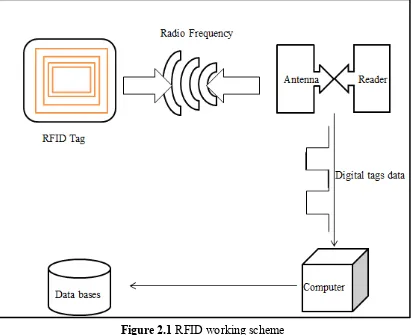
Figure 2.1 RFID working scheme ... 22
Figure 2.2 RFID Reader’s Architecture ... 25
Figure 2.3 RF section of RFID reader ... 26
Figure 2.4 Block diagram of the RFID communication system ... 27
Figure 2.5 RFID cards ... 34
Figure 2.6 RFID tags ... 34
Figure 2.7 The application scheme ... 35
Figure 2.8 System flow of Electronic Toll Payment ... 36
Figure 3.1 System Process ... 37
Figure 3.2 Check-out Flow Chart ... 38
Figure 3.3 Check-in Process ... 39
Figure 3.4 Block Diagram of RFID Intelligent Vehicle Parking System ... 40
Figure 3.5 40-leads PDIP AT89S52 Datasheet ... 41
Figure 3.6 The connections of the input power supply ... 42
Figure 3.7 The pin configurations of BC547 ... 42
Figure 3.8 ID-20LA RFID Reader ... 43
Figure 3.9 Microcontroller’s Connection with LCD Display ... 43
Figure 3.10 USB-ISP flash programmer ... 44
Figure 3.11 UC00A Universal Asynchronous Receiver/Transmitter ... 44
Figure 3.12 Piezobuzzer ... 45
Figure 3.13 Connections of Piezobuzzer... 45
Figure 3.14 Infrared Sensor Used. ... 46
Figure 3.15 Proteus Design Suit ... 47
Figure 3.16 An example of C programming ... 48
Figure 3.17 Virtual Terminal Window of Hyper Terminal ... 48
Figure 4.1 Unique card ID Number ... 50
Figure 4.2 Measurement of Read Range of 125kHz RFID reader ... 50
xiv
Figure 4.4 Graph of Average Reading range (cm) against Book Thickness (cm) ... 54
Figure 4.5 Connections of Probes of Oscillator with the Reader ... 57
Figure 4.6 Graph of Frequency waveforms of 125 kHz reader when card is detected58 Figure 4.7 Coding of Serial Initialization... 59
Figure 4.8 The Stimulation Circuit ... 60
Figure 4.9 Display of project title ... 61
Figure 4.10 Entry of the car park ... 62
Figure 4.11 Reading RFID car at entry ... 62
Figure 4.12 Verification of the identity of the RFID card’s owner ... 63
Figure 4.13 Successful parking process ... 63
Figure 4.14 Car Park Exit ... 64
Figure 4.15 Reading of RFID Card at Exit ... 64
Figure 4.16 Balance Display ... 65
Figure 4.17 RFID Card Not Detected ... 66
Figure 4.18 Condition Car Parking Is Full ... 67
Figure 4.19 Invalid RFID card ... 67
Figure 4.20 Bottom copper view of the PCB layout ... 68
Figure 4.21 Top copper view of the PCB layout... 69
Figure 4.22 PCB board result ... 69
Figure 4.23 Project prototyped with PCB board ... 70
Figure 4.24 8051 Development board ... 70
15
CHAPTER 1
INTRODUCTION
1.0 Introduction
This chapter discussed about the background, problem statements, objectives and limitations of the project.
1.1 Background
1.1.1 Vehicle’s parking system of Shopping Complexes in Malaysia
16 Another alternative method is using the Touch & Go card. Touch & Go cards of customer must have considerable amount of balance before being used to scan it upon entry and when leaving the parking lots. The range of signal is limited. Thus, Radio Frequency Identification (RFID) technology is proposed replace the current payment method.
1.1.2 History of RFID
Radio Frequency Identification (RFID) is an emerging technology which gained popularity in this communication age and headed towards a ubiquitous computing world. The roots of RFID technology can be traced back to
World War II where it was used for airplane identification. The
discovery of this technology was found by Germans to identify which
planes belonged to the enemy and which were a country’s own pilots returning from a mission. (Violino, 2010) [2] Later Scottish physicist Sir Robert Alexander Watson-Watt developed a secret project IFF (Identify Friend or Foe) by the British. The IFF system was the first active RFID system. Each British plane had transmitter placed on it. When signal was received from radar station on the ground, it began transmitting a signal back that identified the aircraft as friendly. RFID works on the same basic concepts. Transponder receives the signal sent by the host. The signal initiates or either reflects back a signal from transponder’s power and broadcast a signal from its own power source or built-in battery, such as the batter in responding antenna or tag. (Eric C Jones, Christopher A.Chung, 2008) [3]
17 before the field of useful application is explored.” (Landt, catlin, 2001)[4] Advances of technology in the development of communication network, computing and integrated circuit are the keys for RFID being widely utilized in the future.
1.1.3 Concept of RFID
RFID system uses radio waves to exchange data between RFID transponders, or tags, and interrogators or reader. RFID readers are devices that perform the interrogation of RFID tags. The primary function of the tag is to transmit data to the rest of the RFID system. RFID technology uses radio wave portion (9 kHz - 3000 GHz) of the electromagnetic spectrum but RFID technology only uses 4 segments of radio wave spectrum. The four segment are 125-134 kHz (Low Frequency), 13.56 MHz (High Frequency), 433 & 860-960 MHz (Ultra High Frequency) and 2.4 & 5.8 GHz (Microwave).The basic principles of RFID are, the tag enters RF field of reader, the RF signal powers the tag, the tag transmits data and ID. Next, the information is captured by the reader, reader sends the data to computer, the computer sends data back to reader, and reader will transmit data back to tag.
1.1.4 Automatic Identification system
18 1.2 Problem Statement
Current manual payment method contributes to the problem of time consuming manual processing of receipts or parking tickets of the car park in shopping complex. This phenomenal is very common nowadays especially on public holidays where shoppers have to queue up to pay the parking fees. Furthermore, shoppers often find inconvenience to wind down the window or move closer to insert the parking tickets. Besides that, authorized car park owner also faces problem in finding out the quantity of available parking spaces in the car park. For the Touch & Go payment method, users only able to have free reload from manual transactions over a few counters available in the area. Users will be charged an additional fee of RM0.50 and RM1.00 at Cash deposit Machine when reload at the ATM or through reload agents. Thus, frequent shoppers who are the users of Touch & Go or Smart card still prefer to use cash for parking fees payments to avoid reloading the Touch & Go or Smart card.
1.3 Objectives of Project
1. To build up the circuit for the RFID system.
2. To obtain the best range or distance of the detection of the RFID tags with the reader.
3. To improve the time efficiency of car park payment processing in shopping complex.
19 1.4 Scope of project
This project would be carried out by implementing the
technology of Radio Frequency Identification (RFID) to replace
current ways of handling parking payment in shopping complex.
The usage of RFID tags would be optimizing for vehicle parking
payment purpose. Although there are many areas that RFID
tags can be used, this project focuses only on all car parks of all
shopping complexes in Malaysia. The range of detection of RFID
tags with the antenna would be studied. This project would also
study the possibility of RFID to be practically implemented in
our country by considering the time and cost efficiency as well
as the maintenance of this technology required once it is
implemented.
The performance of the RFID system on managing the
vehicle’s parking payment depends upon the following factors:
(a)The operation frequency of the reader
(b)The time taken for the tags to be detected
20 1.5 Project Limitation
The implementation of frequency band of RFID in project is
limited to Low Frequency (LF) which is 120 kHz to 150 kHz
due to our implementation of car park payment system does
not require high frequency operation as it is not cost effective
considering the higher power level needed for higher frequency
operation. However, operation of 13.5 MHz RFID system would
be studied for research purpose. The project would focus on
covering the read range of RFID tags but not the speed and
sensitivity of the tags. This is due to the car park payment
system process only one tag at a time upon car entry and
leaving, thus the decoding speed and sensitivity can be kept
21
Chapter 2
LITERATURE REVIEW
2.0 Introduction
This literature review generally discusses about RFID technology and the communication between RFID reader and RFID tag. The implementation of RFID technology in various fields will also be discussed.
2.1 Introduction to RFID
22 Figure 2.1 RFID working scheme
2.1.1 RFID tag
23 There are three types of RFID tags, which are passive tags, active tags and semi active tags. Table 2.1 shows the characteristics different types of RFID tags.
(a)Passive tags
A passive RFID tags do not contain any power source, an electromagnetic (EM) field must be presence in order for a passive RFID tag to generate and reflect radio signal to a reader or interrogator. Since passive tags need to obtain enough power to generate a response, the passive tag must be inside the interrogation zone. The power received from the reader is sufficient to activate any device in the RFID tag and response to reader with the required data. The overall operation to power a RFID tags is, when the tag antenna receives the EM waves transmitted by the interrogator, the current is induced. The induced current is used by the tags to perform backscatter response to the interrogator by sending an amplitude modulated (AM) signal.
(b)Active tags
24
(c)Semi-Passive tags
Semi-Passive tags have the features found in both passive and active tags. Semi-Passive tag uses an internal battery to power up the internal operation of the tag. However, it relies on electromagnetic field power received from the RFID reader to transmit signal to the RFID reader. (Eric C Jones, Christopher A.Chung, 2008)
Table 2.1 RFID tags comparison
Active tags Passive tags Semi-Passive tags
Power Source Internal to tags Energy transfer from the reader via
Continuous Only within field of
reader