INSULATION MONITORING DEVICE
MOHAMAD HAZRIK BIN ABDUL HAMID
A report submitted in partial fulfillment of the requirements for the Degree of
Bachelor of Mechatronic Engineering with Honours
Faculty of Electrical Engineering
UNIVERSITI TEKNIKAL MALAYSIA MELAKA
I declare that this report entitle “Insulation Monitoring Device” is the result of my own
research except as cited in the references. The report has not been accepted for any degree and is not concurrently submitted in candidature of any other degree.
Signature : ...
Student’s Name : Mohamad Hazrik Bin Abdul Hamid
i
ACKNOWLEDGEMENT
In preparing this report, I was in contact with many people, researchers, academicians and practitioners. They have contributed towards my understanding and thought. In particular, I wish to express my sincere appreciation to my project supervisor, Dr. Muhammad Fahmi Bin Miskon, for encouragement, guidance, advice and motivation. Without his continued support and interest, this project would not have been same as presented here.
ABSTRACT
iii
ABSTRAK
Dalam sejarah prosedur pembedahan, pesakit mempunyai kemungkinan untuk
menghasilkan kesan sampingan daripada kejutan elektrik. Secara teorinya, kejutan elektrik ini
disebabkan oleh peralatan electromedikal di dalam bilik perubatan. Tumpuan utama kesan
kejutan elektrik ini adalah apabila adanya kejutan-mikro yang melepasi pesakit semasa
operasi perubatan berlangsung; pesakit terdedah kepada serangan jantung dan boleh
membahayakan nyawa pesakit. Walaubagaimanapun,pengesanan kebocoran arus elektrik
tidak tepat. Objektif utama projek ini ialah untuk mereka dan membina sebuah alat
pemantauan penebat untuk mengesan kebocoran arus pada sistem elektrikal IT. Objektif kedua
ialah untuk mengkaji keupayaan sistem dalam erti kata ketepatan dan kebolehulangan. Untuk
metodologi,sistem cadangan akan menggunakan Arduino Uno dan teori pembahagi voltan.
Data untuk kajian ini dikumpulkan dengan menggunakan dua kaedah iaitu dari persediaan
simulasi dan persediaan eksperimen. Untuk penggunaan simulasi , perisian Proteus Versi 8.0
akan digunakan. Bagi persediaan eksperimen , litar yang mengandungi perintang dekad , dan
soket untuk lampu 100 -W untuk meniru keadaan bilik perubatan akan dibina. Metodologi ini
memberi peluang untuk mendapatkan data untuk ketepatan, kebolehulangan dan sensitiviti.
Penemuan dalam ujikaji ini menunjukkan alat pemantauan penebat mampu mengesan
kebocoran arus elektrik tetapi terdapat ralat dalam mengesan kebocoran arus di dalam
rangkaian sistem elektrikal .Purata peratusan bagi ralat ketepatan ialah 15.683% dan purata
peratusan bagi ralat kebolehulangan ialah 14.59%. Selain daripada itu,kepekaan untuk
pengesanan IMD hanya pada 37.74%.Oleh yang demikian, sebagai cadangan untuk
meningkatkan keupayaan alat ini, mikropemprosesan yang lebih berkuasa harus digunakan
TABLE OF CONTENTS
CHAPTER TITLE PAGE
ACKNOWLEDGEMENT i
ABSTRACT ii
ABSTRAK iii
TABLE OF CONTENTS iv
LIST OF TABLES vii
LIST OF FIGURES viii
LIST OF ABBREVIATIONS x
LIST OF SYMBOLS xi
1 INTRODUCTION 1
1.1 Motivation 1
1.2 Project background 2
1.3 Problem statement 4
1.4 Objective 5
1.5 Scope of work 6
1.6 Project development workflow 6
2 LITERATURE REVIEW 8
2.1 Introduction 8
2.2 Detecting leakage current 9
v
2.2.2 Problem on detecting the leakage of current 10
2.2.3 Solution to available problem 11
2.2.3.1 Detecting the fault current 15 2.2.3.2 Detecting an injected current 16 2.2.3.3 Measuring insulation on every feeder 17
2.3 Earthing systems used 17
2.3.1 Background 17
2.3.2 Problem on choosing the earthing system 18 2.3.3 Analysis on choosing the earthing system 18
2.4 Calculating fault current and contact voltage 21
2.4.1 Background 21
2.4.2 Problem 21
2.4.3 Solution 22
2.5 Comparison on different method to detect leakage of current
24
3 METHODOLOGY 28
3.1 Objective of simulation and experiment 28
3.2 System overview 28
3.3 Materials and equipment 30
3.4 Experimental Setup 31
3.4.1 Parameter for initial experimental setup 33 3.4.2 Precaution to prevent invalidity 34
3.5 Procedure 36
3.5.1 Simulation 36
3.5.1.1 Experiment to find the relationship between theoretical current with measured current and relationship of voltage drop with the resistance
39
3.5.2.1 Experiment to find the accuracy and precision of IMD
40
3.5.2.2 Experiment to find the sensitivity of IMD 42
3.6 Method to Analyze 42
3.6.1 Accuracy experiment on IMD reading 42 3.6.2 Sensitivity experiment on IMD reading 44
4 RESULT AND ANALYSIS 46
4.1 Introduction 46
4.2 Simulation Result 47
4.2.1 Relationship between theoretical current with measured current on 230V condition.
47
4.2.2 Relationship between theoretical current with measured current on 200V condition
49
4.2.3 Relationship between voltage drop with the resistance 53
4.3 Experimental Result 55
4.3.1 Accuracy result on the IMD 55
4.3.2 Precision result on the IMD 58
4.3.3 Sensitivity result on the IMD 59
5 CONCLUSION AND RECOMMENDATION 62
5.1 Conclusion 62
5.2 Recommendation 63
REFERENCES 64
APPENDICES APPENDIX 1 66
APPENDIX 2 67
APPENDIX 3 68
APPENDIX 4 69
APPENDIX 5 70
vii
LIST OF TABLES
TABLE TITLE PAGE
2.1 Comparison between PIM principles on AC,DC and AC& DC network
11
2.2 Table comparing on TN-C, TN-S, TT and IT system 19
2.3 Summary of the advantages disadvantages of earthing systems 20 2.4 Comparison of fault current and contact voltage on first fault 24 2.5 Comparison on different method to detect leakage of current 25 3.1 Parameter that will be used to replicate the medical room
environment
33
3.2 Sensitivity and specificity table 47
4.1 Reading from voltmeter with no load, voltmeter with load and IMD 59
LIST OF FIGURES
FIGURE TITLE PAGE
1.1 The IT (Insulated-Terra) system 3
1.2 System used with no presence of IMD 5
1.3 Project development workflow 7
2.1 Block diagram of the insulation monitoring device (IMD) 9
2.2 Principles of first PIM 10
2.3 Principle of PIM at DC network 12
2.4 Principle of PIM at AC network 13
2.5 Principle of PIM at AC and DC network 14
2.6 IT system network with single insulation fault 15
2.7 Tracking happen by injecting pulse at fixed or portable devices 16 3.1 Insulation Monitoring Device position on an IT system 29
3.2 System overview of the Insulation Monitoring Device 30
3.3a Circuit drawing of experimental setup to provoke real leakage 32 3.3b Laboratory experimental set up to provoke real leakage 32
3.4 Checking the transformer input voltage 35
3.5 Checking the transformer output voltage 36
3.6 IT system parameters 37
3.7 Current measurement and EME simulated by software 38
3.8 Experimental setup for the relationship between the theoretical current with measured current.
39
ix
3.10 Method on taking data for accuracy experiment 43
4.1 Relationship between resistance and current produced 49
4.2 Relationship between I Theory and I Measured 51
4.3 Relationship between percentage errors against resistance 54
4.4 Relationship between resistance and voltage reading 58
4.5 Percentage error of IMD Reading 60
LIST OF ABBREVIATIONS
IT - Insulated-terra
IMD - Insulation monitoring device
PIM - Permanent insulation monitors
N - Neutral
PE - Protection earth
xi
LIST OF SYMBOLS
Id - Fault current flowing on earth connection resistance of the frame.
C1 - Earth impedance capacitive component for phase 1. C2 - Earth impedance capacitive component for phase 2. C3 - Earth impedance capacitive component for phase 3.
ZN - Additional impedance connected between neutral point and earth in IT
system.
RB - Resistance of natural earth connection
UD - Contact voltage between frame and earth
CHAPTER 1
INTRODUCTION
This chapter will discuss about the project background, motivation, problem statement, project objective and scope of work for the insulation-monitoring device.
1.1 Motivation
2
A much debated question is whether the insulation-monitoring device able to detect leakage of current in the medical environment in term of accuracy and sensitivity. Others researcher trying to get the value of the leakage current using different method such as differential current between two points [1], technique of the balanced voltmeter [3], direct current (DC) current injection method [3] and many more. Based on the method that being mention before, there are pros and cons for each method in term of accuracy and sensitivity of the detection.
Furthermore, the insulation-monitoring device is meant to help the medical sector by reducing the patient risk towards the electric shock especially in an operation room. From the Malaysian Electrical Installations of Building 2009 standard [16], the medical IT system should be set up with an insulation-monitoring device. Previously from International Electrical Installation of Building for Medical Environment 2002 [13], the usage of insulation-monitoring device should helps the IT system to perfectly detect leakage of current in medical environment. Malaysian government should obligate every hospital and medical clinic to install the insulation-monitoring system in IT system electrical network. Thus, the importance of the device have been studied and researched since 2002 to solve the micro-shock problem especially in an operation room. So, the insulation-monitoring device has the best way to overcome the leakage of current especially in medical environment.
1.2 Project Background
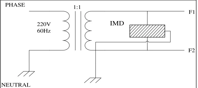
types of electrical shock; direct contact to an exposed live conductor and indirect contact. In this report, we will investigate the indirect contact, which happens when leakage of current occurred. Previous studies have reported about death cause by electrical shock during the surgery [2]. Due to these accidents, researchers want to minimize the problems by suggesting their proposals to prevent the leakage of current. IT system in figure 1.1 has the ability to prevent the leakage of current and any power interruption during a surgery. The system in Figure 1.1 namely Insulated and Terra system principles are naturally earthed by the high impedance up to 1500Ω. The neutral port of transformer is not earthed but it is actually unearthed by the capacities of network cables. The system is designed to preclude an electric spark that is not dangerous to human, especially the patient during surgery. To increase the safety for the usage of the system, an isolation transformer will be introduced together with the insulation-monitoring device. The insulation-monitoring device will trigger the alarm and gives the signal if there is leakage of current within the electrical lines. The IT system must be equipped with the insulation monitoring device in order to comply with the Malaysian standard for medical room, IEC 61557-8. Thus, developing an insulation-monitoring device will surely help the medical sector to prevent any electric shock especially in the operation room.
Figure 1.1: The IT (Insulated –Terra) system
PHASE
NEUTRAL
220V 60Hz
1:1
F1
4
1.3 Problem statement
Electric shock is a classic problem in medical sector. In order to solve this problem, researchers are working on to design an earthing system that can prevent electric shock in the operation room. The researchers introduced various standardized earthing systems, which given the international standard for medical room (IEC 60364). IT system is one of the systems that meet the international and Malaysian standard. Figure 1.2 shows that the IT system with no presence of IMD, which can risk the patient if the electro medical equipment having an insulation failure. From figure 1.2, resistance of patient is at 51kΩ, which is not a safe condition for a patient. Micro-shock will be produced when the current induced threshold is at or below 51k and can cause death.
Insulation monitoring device is a device used to detect leakage of current at medical environment, military sector, server room and many more. This device can alert and gives alarm to the users whenever there is a leakage of current across the electrical line. However, the problem came when the detection of the leakage of current is not accurate. According to IEC 61557-8 standard, an insulation-monitoring device should be able to detect the current induced threshold of below or equal to 51kΩ. Failure to detect the leakage of current can lead the patient to experience the micro-shock. Furthermore, method of detecting leakage of current must be suitable for an insulation-monitoring device as accuracy is the most important factor to detect leakage of current.
the insulation monitoring device design must follow the international electrical standard. On top of that, suitable earthing system and the technique to detect the leakage of current must not be taken lightly as both criteria are the most important part in increasing the accuracy and precision of the device.
Figure 1.2: IT System used with no presence of IMD [1]
1.4 Objectives
The objectives of this project are
1. To design and develop an insulation-monitoring device for detecting the leakage current in IT electrical network system.
6
1.5 Scope of Work
1. This project is developed currently to be used in single phase power supply 2. Supply voltage is 200VAC with current rating 31.5 kA.
3. This device detects the current leakage in single-phase power supply only.
4. To prove the accuracy and precision of the device, several experiments in the lab are performed.
5. Simulation using Proteus 8.0 software will be used to analyze the hardware functionality and experimental set up.
6. The design and development of the hardware are based on Malaysian Electrical Building Installation 2009.
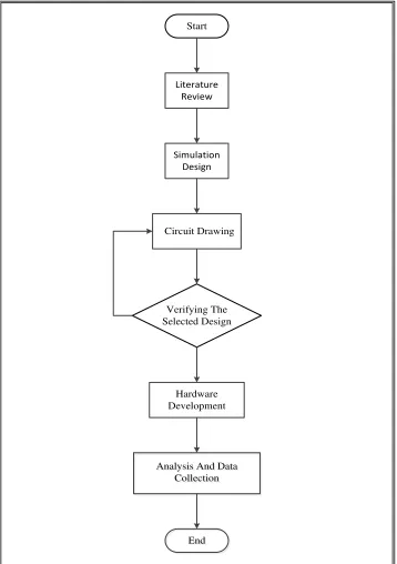
1.6 Project Development Workflow
Figure 1.3: Project development workflow
Start
Literature Review
Circuit Drawing
Simulation Design
Verifying The Selected Design
Hardware Development
Analysis And Data Collection
Analysis And Data Collection
End
8
CHAPTER 2
LITERATURE REVIEW
For this chapter, the collections of information that related to the system development of the insulation monitoring device has been search, evaluate and analysis. Any backgrounds, problems and solution regarding the development of the device will be covered in this chapter.
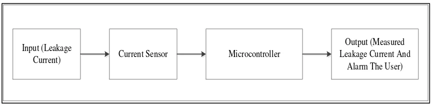
2.1 Introduction
finally will bring out the output. The outputs are in the form of alarm sound and display on a led panel.
Figure 2.1: Block diagram of the Insulation Monitoring Device (IMD)
2.2 Detecting leakage current
2.2.1 Background
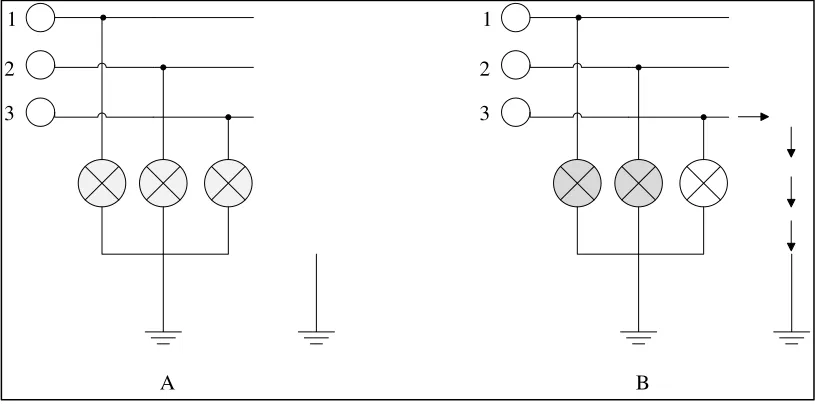
Previous studies have reported the method to detect a fault by using the first principles of PIM (permanent insulation monitor)[3]. Figure 2.2 is to explains about the first principles of PIM. At A, all the bulbs lit at the same rate of brightness because of the balanced three-phase load supplied throughout the bulbs. That means the current flowing consistently at same value throughout the bulbs[3]. So when the system experiencing the leakage of current, one of the bulbs is not lit and will be connected by the fault impedance, which can be seen at B. Voltage is decreasing at the terminal of the bulb 3 and, the bulb’s brightness for the bulb 1 and bulb 2 are increasing until they reach the maximum voltage phase. Recent developments in fault tracking method have improved the previous method, which are needed to stop the operation of every feeder until the insulation faulty can be found. This new method can detect insulation faulty without power breaking to the system that can save more time to the user to stop each operation of feeder.
Input (Leakage
Current) Current Sensor Microcontroller
Output (Measured Leakage Current And
10
Figure 2.2: Principles of first PIM
2.2.2 Problem on detecting the leakage of current
For tracking an insulation fault, there are two ways to find the fault, which are tracking by successive de-energisation of feeders and live tracking. The operators (users) need to open every feeders starting with the main feeders for the tracking by successive de-energisation of feeder method. By applying the first principles of PIM, whenever the feeder that experiencing the leakage of current is opened, the current injected by the PIM will decrease and drop under the detection level. However, by applying this method, the users need to interrupt the operation of each feeder until the location of the insulation faulty is confirmed.
1
2
3 1
2
3
![Figure 1.2: IT System used with no presence of IMD [1]](https://thumb-ap.123doks.com/thumbv2/123dok/476270.52121/19.595.103.508.216.431/figure-used-presence-imd.webp)