DOI: 10.12928/TELKOMNIKA.v11i3.1048 495
Relationships between Excitation Voltage and
Performance of AFWR Synchronous Generator
Abdul Multi*1, Iwa Garniwa2
Faculty of Engineering, Universitas Indonesia, Depok 16424 *Corresponding author, e-mail: [email protected], [email protected]
Abstrak
Generator fluks aksial rotor belitan mempunyai belitan medan yang dihubungkan dengan sumber tegangan dc. Dengan mengatur tegangan eksitasi, maka unjuk kerjanya dapat diatur untuk memenuhi kebutuhan tegangan beban yang terpasang pada terminalnya. Generator yang dirancang berkapasitas skala kecil yang mempunyai1 kW, 380 V and 750 rpm. Generator mempunyai satu stator belitan dua sisi beralur yang diapit oleh rotor kembar. Pengaruh perubahan tegangan eksitasi terhadap unjuk kerja dapat dilihat dari hasil perhitungan yang menggunakan persamaan-persamaan.Hasil-hasil perhitungan menunjukkan besaran listrik telah memenuhi unjuk kerja mesin. Semakin tinggi tegangan, semakin rendah rugi-ruginya sedangkan efisiensi dan torsinya semakin tinggi. Telah diperoleh bahwa untuk tegangan eksitasi 11 V, maka efisiensi dan torsinya masing-masing 85,12 % and 13,04 Nm.
Keywords: Generator sinkron, fluks aksial, tegangan eksitasi, efisiensi, torsi.
Abstract
The axial flux wound rotor generator has field winding that should be connected to a dc voltage source. Varying the excitation voltage, its electric performance might be controlled to meet the need of a load voltage attached to its terminal. The generator designed is small-scale capacity which has 1 kW, 380 V and 750 rpm. The generator has a single double-sided slotted wound stator sandwiched between twin rotor. The effect of excitation voltage changes on its performance can be seen from the result of calculations using the given equations.The calculation results reveal electric quantities suited with respect to performance of the machine. If the voltage is higher then the losses will be lower. However, the higher the voltage, the higher the efficiency and the torque.It has been found out that for the excitation voltage11 V, the efficiency and the torque are 85.12 % and 13.04 Nm respectively.
Keywords: Synchronous generator, axial flux, excitation voltage, efficiency, torque.
1. Introduction
As for the axial flux permanent magnet (PM) machines, they have a number of distinct advantages over radial flux machines (RFM). They can be designed to have a higher power-to-weight ratio resulting in less core material. Moreover, they have planar and easily adjustable airgaps. The noise and vibration levels are less than the conventional machines. Also, the direction of the main air gap flux can be varied and many discrete topologies can be derived. These benefits present the AFMs with certain advantages over conventional RFMs in various applications [1].
Electrical machine which has high power and high efficiency and also small dimensions while lower price is the axial flux permanent magnet machine. However, the study has not been performed yet in three phase axial flux wound rotor synchronous generator which the excitation voltage can be varied. The excitation voltage changes can affect machine parameters such as efficiency, losses and load torque.
This research will analyze the effect of the excitation voltage changes on the performance of three phase axial flux synchronous generator. How it affects the efficiency, the current and the torque. With the limited generator output power, it will be sought at what excitation voltage is varied to obtain the highest efficiency. When the rotation of generator rotor is not constant caused by the prime mover rotation that is not constant, the output voltage generated by the generator varies. To make aconstant output voltage, the flux should be controlled by varying the field current flowing through the rotor winding. Therefore the expected advantage of the result of this study is to obtain a precise excitation voltage on the axial flux wound rotor (AFWR) synchronous machine having the capacity 1 kW with high efficiency.Since a large number of poles can be accommodated, these machines are ideal for low speed applications.
Figure 1. Axial flux machine configurations. (a) Single rotor - single stator structure, (b) Two rotor
- single stator structure, (c) Single rotor -two stator structure, (d) Three rotor - two stator structure.
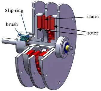
Figure 2. AFWR synchronous generator
In the case of engine/generator sets most interest has focused on axial flux generator topologies that have two rotor discs and one stator disc. Such an axial flux generator can be usefully integrated with an engine as it is axially very short and so can be mounted directly on the engine output shaft, eliminating the need for separate bearings or couplings. The generator has, or can be designed to have, a moment of inertia that makes the flywheel redundant [3].
An axial flux machine with wound rotor is referred to as an axial flux wound rotor (AFWR). A cross sectional schematic of the AFWR machine is shown in Figure 2. The AFWR generator consists of two wound rotor that two windings are connected in parallel. The stator of AFWR generator is located between two opposing wound rotors. The double-sided rotor simply called twin rotor with slots are located at sides of stator and rotor lamination core.
2. Research Method
The design of axial flux synchronous generator is performed by calculations based on the equations of the axial flux and the radial flux machines. Equations applied are related to electric circuits, magnetic circuits and mechanics on the stator and the rotor. The Matlab program is used for accuracy and precision calculations, while Solidworks software is used for drawing the machine and its parts.
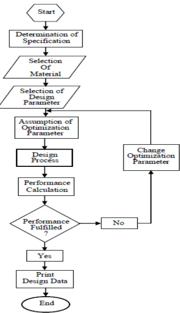
design of the electrical circuit, the magnetic circuit and the mechanics, it is first assumed the parameter optimizations associated with the specification of the machine. It is expected at the end of the design process, the performance of the machine is met the need. If the performance has not met yet, then the design process should be repeated by changing optimization parameters. If the performance has been met, the design data sheet can be printed. Stages of the design are shown in the flow chart in Figure 3. The process of optimization in the design of the machine aims to obtain higher efficiency with power output fixed previously.
The machine designed is three phase axial flux wound rotor (AFWR) synchronous generator where magnetic flux lines cross the air gap in axial direction with the machine axis. The stator and rotors are disc shaped and located in parallel next to each other. The stator having two side slots are located between twin slotted rotors. Windings are then laid into slots carved in the rotor and stator face shown in Figure 4.
Figure 3. The flow chart of design process
Figure 4. The slotted stators and rotor, before and after winding
In principle, the electromagnetic design of AFPM machines is similar to its radial flux PM (RFPM) counterparts with cylindrical rotors. However, the mechanical design, thermal analysis and assembly process are more complex [4]. Specifications of three phase AFWR synchronous generator designed is the nominal quantity (rated). Quantities include output power, terminal voltage (phase to phase), frequency, rotor rotation and power factor. The input power and the load torque are on the shaft of prime mover which rotates the generator rotor windings. The rotor winding is connected to a source of direct current so that the field current flows through the field winding. The field current produces a steady-state magnetic field in the rotor.
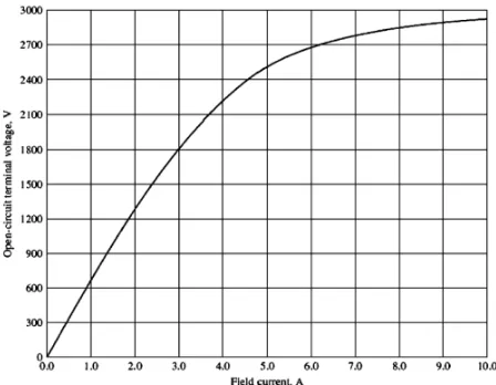
winding. The internal generated voltage in the stator winding is proportional to the flux. Relation between the field current andthe internal generated voltage is shown in Figure 5. With this characteristic, it is possible to find the internal generated voltage of the generator for anygiven field current [6].
Figure 5.Open-circuit Characteristics of a synchronous generator
The real electrical output power of the synchronous generator can be expressedin phase quantities as Equation 1-5.
P m V I cosφ (1)
Stator cooling coefficient (C )
C ,, (2)
peripheral spee
Stator dissipation koefficient (C )
C (3)
Total losses in the stator (P )
P ∆P P (4)
stator temperature rise ( )
(5)
V , (6)
Voltage across each field coil
E (7)
Resistance of each field winding
(8)
Current in field winding
(9)
Dissipation coefficient (C )
C (10)
Total loss in rotor (P )
P P P (11)
Rotor temperatur rise ( )
(12)
Losses produced by the machine in thermal consist of electrical and mechanical losses.
1. Copper losses ∆P are the resistive heating losses in thearmature winding and the field winding.
2. The core losses(P ) are the hysteresis losses and eddy current losses occurring in the metal of the machine. The core losses are taken as 5% of output power.
3. Friction and windage losses (P& ). Friction losses are losses caused by the friction of the bearings in the machine, while windage losses are caused by the friction between the moving parts of the machine and the air inside the motor's casing. The friction and windage losses are taken as 1% of output power [7].
4. Excitation losses (P ) contain field winding DC losses and brush and slip-ring losses. In the design of drop voltage in each brush is less than 1 volt [5].
5. Stray load losses or miscellaneous losses (∆P )are taken as 20% of the total copper losses.
Efficiency at full load
x % (13)
Load torque
τ (14)
3. Results and Analysis
The values of machine parameter obtained by the calculation with the help of MATLAB are used for analysis of the machine based on the output power. Core losses and friction and windage losses are assumed 5% and 7% of the output power respectively [1, 8]. The research issue is directed to excitation voltage changes that affect losses, efficiency and load torque of the machine. The output power is set to a fixed quantity initially, while the efficiency is sought to the highest quantity. Changing the excitation voltage, losses and efficiency also change.
The efficiency is sought in the optimal value but with a fixed output power. The optimum efficiency is obtained by changing the excitaion voltage. The machine operation specifications required are shown in Table 1.
The calculation results related to the performance of the machine at the output power 1 kW and the efficiency 85,12% are shown in Table 2. Varying the excitation voltage, the other machine parameters also change. In the calculation of the efficiency, the excitation voltage is ranged from low to high values while the efficiency and output power is checked and selected.
Table 1. Required specifications of machine operation
Quantity (Unit) value
Output power (W) 1000
Terminal voltage (V) 380
Number of poles 8
Frequency (Hz) 50
Power factor 0,83
3.1.Excitation Voltage Parameter
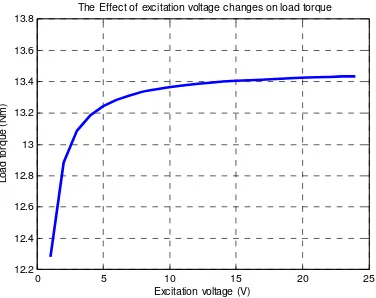
Theexcitation voltage 11 V obtained from the calculation reveals the best solution (optimal efficiency). The effect of excitation voltage changes on losses, efficiency, output power and torque are shown in Figure 6, 7, 8and 9 respectively.The calculation results showing the performance of the machine at the output power 1 kW and the efficiency 85,12% are shown in Table 2.
Table 2. Optimization parameter on the efficiency 85,12% and the output power 1kW.
Quantity (Unit) Value
Excitation voltage (V) 11
Line current (A) 1.94
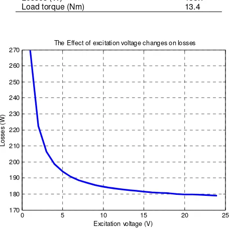
Losses (W) 183.7
Load torque (Nm) 13.4
Figure 6. Relationships between excitation voltage and losses.
0 5 10 15 20 25
The Effect of excitation voltage changes on losses
Figure 7.Relationships between excitation voltage and efficiency.
Figure 8. Relationships between excitation voltageand output power.
If the excitation voltage increases, then the efficiency,output power, load torque and stator temperaturewill increase too. Meanwhile, losses and rotor temperature will decrease as shown in Figure 10 and 11.
Figure 9. Relationships between excitation voltage and load torque
Figure 10. Relationships between excitation voltage and stator temperatur
Figure 11. Relationships between excitation voltage androtor temperatur
0 5 10 15 20 25
The Effect of excitation voltage changes on efficiency
Excitation voltage (V)
The Effect of excitation voltage changes on output power
Excitation voltage (V)
The Effect of excitation voltage changes on load torque
Excitation voltage (V)
The Effect of excitation voltage changes on stator temperature
Excitation voltage (V)
The Effect of excitation voltage changes on rotor temperature
3.2.Design Analysis
Calculation of the effect of excitation voltage changes on AFWR generator has been performed by Matlab sofware. The changes of excitation voltage affect the performance of the machine. The higher the excitation voltage, the higher output power, efficiency, load torque and stator temperatur, but the lower losses and the rotor temperature.
The magnitude of the losses is inversely related to the output power. Thesmaller a machine's losses, the larger the output power it is capable ofachieving so that the efficiency and load torque will be larger.
According to Ohm’s lawthat the electrical current flowing in an circuit is directly proportional to the voltage. Therefore, if the voltage is increased, the current will increase too.While temperature in the stator is affected by its losses and the losses are directly proportional to current squared.Therefore, if the excitation voltage increases, the stator temperature increases too.
The efficiency 85.12% obtainedon the excitation voltage 11 V and total losses 183.7 W are constrained to be 1 kW. If the efficiency in the calculation is changed, then machine parameters are changed too including power input and power output.
4. Conclusion
From the calculation andthe analysis of the effect of excitation votage changes on AFWR synchrounous generator, the conclusion can be drawn as follows:
1. The higher the excitation voltage, the higher the resulting power, efficiency and load torque of the machine.
2. The higher the excitation voltage, the lower the losses of the machine
3. The increased excitation voltage is constrained by the capacity of the designed machine.
References
[1] M Aydin, S Huang, TA Lipo. Axial Flux Permanent Magnet Disc Machines: A Review. Wisconsin
Electric Machines & Power Electronics Consortium, University of Wisconsin-Madison, Madison, WI 53706-1691, 2004: 1-4.
[2] Asko Parviainen. Design Of Axial-Flux Permanent-MagnetLow-Speed Machines And Performance Comparison Between Radial-Flux and Axial-Flux Machines. PhD Thesis. Digipaino: Lappeenranta University of Technology; 2005.
[3] JR Bumby, R Martin. Axial Flux, Permanent Magnet, Generators For Engine Integration. The 12th
International Stirling Engine Conference. Durham. 2005: 1-5.
[4] JF Gieras, Rong-Jie Wang, MJ Kamper. Axial Flux Permanen Magnet Brushless Machines. London: Kluwer Academic Publishers. 2004: 1-8.
[5] Ion Boldea. The Electric Generators Handbook: Synchronous Generators.Boca Raton: Taylor & Francis Group. 2006: 72-75.
[6] Stephen J Chapman. Electric Machinery Fundamentals. Fourth Edition. Singapore: McGraw-Hill, Inc. 2005: 283-292.
[7] KM Vishnu Murthy. Computer-Aided Design of Electrical Machines. Hyderabad: BS Publications. 2008: 160, 231.