TELKOMNIKA, Vol.14, No.1, March 2016, pp. 82~85
ISSN: 1693-6930, accredited A by DIKTI, Decree No: 58/DIKTI/Kep/2013
DOI: 10.12928/TELKOMNIKA.v14i1.2296 82
Received July 7, 2015; Revised January 4, 2016; Accepted January 15, 2016
Design of Compact Microstrip U Shape Bandpass Filter
Using Via Ground Holes
Fajri Darwis*1, Arief Budi Santiko1, Novita Dwi Susanti1 1
Research Center for Electronics and Telecommunication – Indonesian Institute of Sciences (PPET-LIPI), Kampus LIPI, Jl. Sangkuriang Building 20 4th floors, Bandung, 40135 – Indonesia,
Phone/fax: +62-22-2504661/+62-22-2504659 *Corresponding author, email: [email protected]
Abstract
This paper present the microstrip bandpass filter using two U shape resonators with using via ground holes. The bandpass filter was established using two U shape resonators with using via ground holes and deployed on RT/duroid 6010 LM aims to minimize the dimension of filter. The proposed filter was characterized using software simulation. The characteristic of proposed filter is to deal with required specification. Hardware realization was done to verify the characteristic of proposed filter. The bandpass filter has the dimension of 4.2 mm x 3.8 mm. The filter was expected to have center frequency of 400 Mhz with minimum 3dB bandwidth of 15 Mhz, maximum insertion loss of -1.5 dB and VSWR less than 2. VSWR and 3dB bandwidth on realized filter have a good agreement with required specification. However the insertion loss and center frequency was not adequate. The realized filter has insertion loss of -2.554 dB with the center frequency of 404.711 MHz.
Keywords: filter; U shape resonator; duroid 6010LM; ground holes
Copyright © 2016 Universitas Ahmad Dahlan. All rights reserved.
1. Introduction
Nowadays, development of microstrip filters including bandpass filter is growing rapidly. Bandpass filter is a component which is used to pass desired region frequency with certain center frequency. In communication system, bandpass filter is used in transmitter and receiver. High performance of filters is required in radar system.
In radio frequency, filter is designed using lumped elements components such as capacitor and inductor. This filter has been implemented in coastal surveillance radar in PPET-LIPI [1]. When designing filter using lumped elements, the values of capacitor and inductor that we can acquired from calculate the formula, are difficult to obtain in the market so that we use the values close to which designed or use tunning components. Therefore, we need the much effort to fabricate the filter. Due to the problem, anothers design is required to overcome the problem and to reduce the cost of fabrication
The design filter using microstrip line is used by many researchers [2-13]. One of method is U-shape resonator or it is called hairpin resonator. Hairpin line is a compact structure. It is obtained by deflecting line resonator like a U letter. The length of resonator is half-wavelength. For the radio frequency, hairpin line resonator has a long line. It makes the dimension of filter become quite large. Some techniques have been done by researcher to reduce the dimension of filter [8-13]. In [8], fractal Koch geometry was added in hairpin resonator. This design can be minimized the dimension approximately 20% from the conventional design. The square groove technique was used by [9] to miniaturize the filter and suppress the second harmonic. In [10], an interdigital hairpin resonator was presented. It replaces the hairpin resonator to an interdigital capacitor. The other techniques to minimize the dimension of filter are with using via ground holes. It has been presented by [11-13]. This technique can be reduced the dimension of filter about 35 -37 % as in [11-12].
TELKOMNIKA ISSN: 1693-6930
Design of Compact Microstrip U Shape Bandpass Filter Using Via Ground Holes (Fajri Darwis) 83
use substrate that has higher dielectrict constant. For the substrate we choose RT/duroid 6010 LM. This substrate has typical dielectric constant of 10.2. Therefore, with combine the techniques, the filter can be more compact. Prior to bandpass filter fabrication, numerical characteristic of bandpas filter was characterized by using software simulation. For the experiment, the bandpass filter was realized and used SMA connector in both of input and output. Finally, the measurement results and its analysis will be presented.
2. Filter Design and Simulation
The bandpass filter was designed using U shape resonator. We called the U shape resonator as hairpin resonator. The resonator is made using lines that deflected like U letter with the length is λ/2. In this design, the bandpass filter has the center frequency of 400 MHz. In this frequency, filter acquires quite a long resonator line. It cause the dimension of filter becomes quite large. So the compact filter is nedded.
In order to reduce the dimension of filter, the filter only use two U shape resonator that arranged series with couple feed line. Besides that, the model with using via ground holes is designed in both of line resonator. Furthermore the substrate which has higher dielectric constant is used. The filter deploys on RT/duroid 6010 LM substrate with the typical values as follows:
a) Dielectric constant г = 10.2
b) Dissipation factor tan = 0.0023 c) Thickness of substrate = 1.27 mm d) Copper cladding = 35 µm
The proposed design of bandpass filter is depicted in Figure 1. The values of parameter in this filter design as follows: L1 = 4.25 mm; L2 = 27.45 mm; L3 = 9 mm; S1 = 4.5 mm; S2 = 0.3 mm; W1 = W2 = 1.6 mm; D (radius) = 0.5 mm.
Figure 1. Structure of bandpass filter Figure 2. Simulation result of bandpass filter
The software simulation ADS 2011.10 is used to characterize the design and to obtain the optimum performance of the filter such as center frequency, insertion loss, return loss and working bandwidth. The performance of bandpass filter is plotted in Figure 2. The insertion loss at center frequency of 400 MHz is -0.783 dB. While the 3 dB working bandwith for this filter is 15 MHz with range from 392.3 MHz to 407.3 MHz. The return loss at center frequency is -19.160 in both of ports input and output. It is same with the VSWR of 1.25.
From the simulation results, it can be inferred that the characterization results of the filter have a good performance.
3. Realization and Characterization
ISSN: 1693-6930
TELKOMNIKA Vol. 14, No. 1, March 2016 : 82 – 85 84
both of ports input and output as shown in Figure 3. For the ground hole, we drill with radius 0.5 mm and then soldered.
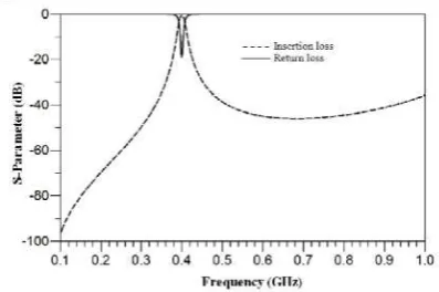
From the Figure 3, we obtain the dimension of bandpass filter of 4.2 mm x 3.8 mm. VNA Advantest is used to characterize the realized filter. The measurement results of filter are shown in Figure 4 till 6. From the results, it seems the center frequency of realized filter is different with the simulated result, 400 MHz. While for realized filter, the center frequency is 4.711 MHz higher than simulated one. This is probably evoked by dielectric constant of the substrate when designing.
Figure 4 shows the insertion loss characteristic of realized filter. In the center frequency of realized filter, the insertion loss is worse than the simulated one. This is probably caused by inappropriateness of RF cables which is used in measurement and poor soldered at ground hole. The 3 dB working bandwith of realized filter is 0.957 MHz higher than the simulated one with range from 397.302 MHz to 413.259 MHz.
Figure 3. Picture realized of bandpass filter Figure 4. Measurement result of insertion loss
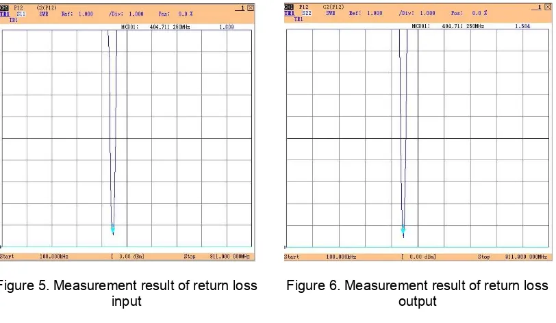
The VSWR input and output are depicted in Figure 5 and 6. In General, the VSWR in both of ports shows a good performance with the values less than 2. The difference performance of VSWR in realized filter compared to VSWR in simulated one is probably caused by bad connection between transmission line and connector.
Figure 5. Measurement result of return loss input
TELKOMNIKA ISSN: 1693-6930
Design of Compact Microstrip U Shape Bandpass Filter Using Via Ground Holes (Fajri Darwis) 85
The results of realized filter and simulated results show not good agreement especially at insertion loss. This is probably evoked by in accurate of fabrication process.
Compare with another design [13], this propose design has a better performance. The insertion loss of the proposed design is 3.013 dB better than the design in [13] but still need to be improved.
4. Conclusion
The bandpass filter using two U shape resonators with using via ground hole has been demonstrated. The bandpass filter has been fabricated on RT/duroid 6010 LM dielectric substrate. The comparison between simulated and realized filter has been presented. From the characterization results, it has been shown that the filter has a narrow bandwith with the 3 dB bandwidth is about 15.957 MHz and the center frequency of realized filter 4.711 MHz higher than simulated one.
Acknowledgements
I would like to thank to Research Center for Electronics and Telecommunication (PPET-LIPI) for support and cooperation.
References
[1] Kurniawan D, Adhi P, Satyawan AS, Syamsu I, Praludi T. Object Detector on Coastal Surveillance Radar Using Two-Dimensional Order-Statistic Constant-False Alarm Rate Algoritm. TELKOMNIKA Indonesian Journal of Electrical Engineering. 2015; 13(2): 624-631.
[2] Hong JS, Lancaster MJ. Microstrip Filters for RF/Microwave Applications. New York: John Wiley & Sons. 2001: 139-133.
[3] Darwis F, Santiko AB. Desain dan Simulasi Microstrip Hairpin Bandpass Filter untuk Aplikasi S-Band. Seminar Ilmu Pengetahuan Teknik. Yogyakarta. 2013: 425-427.
[4] Abdipour M, et al. Design and Simulation of Microstrip Bandpass Filter. International Conference on Signal, Image Processing and Applications. Singapore. 2011: 233 -236.
[5] Vidhya K, Jayanthy T. Design of Microstrip Hairpin Band Pass Filter Using Defected Ground Structure and Open Stubs. Singapore. 2011: 268-272.
[6] Militaru N, Lojewski G. Design of Microwave Microstrip Bandpass Filters using Defected Ground Structures. U.P.B. Sci. Bull., Series C. 2006; 68(4): 3-12.
[7] Chen W, Zhao Y, Jun Z. Compact and Wide Upper-Stopband Triple-Mode Broadband Microstrip BPF.
TELKOMNIKA Indonesian Journal of Electrical Engineering. 2012; 10(2): 353-358.
[8] Munir A, Praludi T, Effendi MR. Characterization of Narrowband Hairpin Bandpass Filter Composed of Fractal Koch Geometry. Progress in Electromagnetic Research. Guangzhou. 2014: 1843-1846. [9] Srisathit K, Tangjit J, Surakampontorn W. Miniaturized Microwave Bandpass Filter Based on Modified
Hairpin Topology. International Conference of Electron Devices and Solid-State Circuits. Hongkong. 2010: 1-4.
[10] Zhu J, Feng Z. Microstrip Interdigital Hairpin Resonator with an Optimal Physical Length. IEEE Microwave and Wireless Components Letters. 2006; 16(12): 672-674.
[11] Hasan A, Nadeem AE. Novel Microstrip Hairpinline Narrowband Bandpass Filter Using Via Ground Holes. Progress in Electromagnetics Research. 2008; 78: 393-419.
[12] Zulkifli FY, et al. Microstrip Hairpin Bandpass Filter Using Via Ground Holes for 923 MHz RFID Application. International Symposium on Antennas and Propagation (ISAP). Jeju. 2011.