DOI: 10.12928/TELKOMNIKA.v11i3.1041 425
Numerical Calculation of Transient Thermal
Characteristics in Gas-Insulated Transmission Lines
Li Hongtao, Shu Naiqiu, Li Ling*, Wu Xiaowen
School of Electrical Engineering, Wuhan University No.8, Donghunan Road, Hongshan District, Wuhan 430072, China
*Corresponding author, e-mail: [email protected]
Abstrak
Guna kajian mendalam karakteristik termal pada jalur transmisi gas terisolasi (gas-insulated transmission lines, GILs) terpasang di atas tanah, model elemen-hingga medan cairan kopling dan medan panas didirikan, di mana asumsi yang sesuai dan kondisi batas yang diberikan. Proses kenaikan suhu transien GIL pada kondisi suhu lingkungan variabel, kecepatan angin dan radiasi matahari diinvestigasi. Kondisi ekuivalensi koefisien perpindahan panas konvektif permukaan dan kondisi batas fluks panas diperbarui dalam proses analisis. Berbeda dengan metode elemen hingga (finite element method, FEM) tradisional, pada penelitian ini variabilitas sifat termal terhadap suhu dipertimbangkan. Hasil perhitungan divalidasi oleh hasil tes penelitian lain. Simpulan memberikan metode dan dasar teori untuk kajian mendalam karakteristik kenaikan suhu transien GILs di lingkungan terbuka.
Kata kunci: fluks panas, kenaikan suhu transien, koefisien transfer panas konvektif, lingkungan terbuka, model elemen-hingga
Abstract
For further knowledge of the thermal characteristics in gas-insulated transmission lines (GILs) installed above ground, a finite-element model of coupling fluid field and thermal field is established, in which the corresponding assumptions and boundary conditions are given. Transient temperature rise processes of the GIL under the conditions of variable ambient temperature, wind velocity and solar radiation are respectively investigated. Equivalent of surface convective heat transfer coefficient and heat flux boundary conditions are updated in the analysis process. Unlike the traditional finite element method (FEM), the variability of the thermal properties with temperature is considered. The calculation results are validated by the tests results reported in the literature. The conclusion provides method and theory basis for the knowledge of transient temperature rise characteristics of GILs in open environment.
Keywords: convective heat transfer coefficient, finite element model, heat flux, open environment, transient temperature rise
1. Introduction
The trend of increasing power consumption needs higher electrical energy to be transported from the power plants to load centers. Construction of more overhead lines and pole towers is not suitable for environmental protection especially in metropolitan areas. Gas-insulated transmission lines (GILs) represent a new technology for high power transmission instead of traditional overhead lines and cables, with the advantages such as space saving, high transmission capability and low energy loss [1-6].
FEM to investigate the thermal problem of turbulent natural convection in a 400kV GIL. However, in addition to temperature dependent physical parameters such as gas density, dynamic viscosity and thermal conductivity, the complex environmental factors are not contemplated in these models. For the operating GILs, especially the GILs installed above ground, the temperature rise will be greatly influenced by the ambient temperature, wind velocity and solar radiation. In order to study the heat transfer characteristics of the GILs comprehensively, it is necessary to analyze the temperature variation of the GILs under different environments.
In this paper, the coupled fluid and thermal finite element model is established. Heat transfer of conduction, convection and radiation in the GIL are considered. The temperature dependent heat transfer coefficients on the enclosure surface, electrical and thermal properties of the materials are updated in the iterative procedure. Wind and solar radiation are equivalent to convective boundary condition and heat flux boundary condition, respectively. Temperature rise characteristics of the GIL under time varying ambient temperature, wind velocity and solar radiation are analyzed with the proposed model. The predicted temperatures are validated against test results reported in the literature.
2. Solution Region and Basic Assumptions
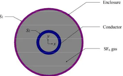
GIL is mainly composed of aluminum enclosure, conductor, epoxy resin insulators, particle trap and insulating gas (SF6). The structure is deemed symmetrical. In order to reduce
the computation cost without the loss of accuracy, a two-dimensional (2-D) model is employed in the solution procedure, as shown in figure 1. The analysis presented in this paper is based on the following assumptions:
- The GIL is infinitely long.
- Radiation effect of the SF6 gas is disregarded.
- The density, viscosity and conductivity of the SF6 gas and air are temperature dependent,
while the specific heat is considered as constant.
- Heat transfer coefficient on the enclosure surface is temperature dependent.
- Contacts, insulators and particle traps, which have little influence on the temperature distribution of the whole GIL, are excluded in the solution region.
Figure 1 Solution region of the thermal field
3. Thermal Analysis
In the thermal analysis of GIL, the heat transfer mechanisms are conduction, convection and radiation. The heat generated in the conductor and the enclosure is transferred from the interior surface to the external surface by conduction. There are two convection types in the model, natural and forced convection. Natural convective heat transfer, which is caused by the density difference of the fluid, exists at the interface of the SF6 gas and the conductor and that
of the SF6 gas and the enclosure. Forced convection is deemed to happen on the outer surface
approximately 60% of the heat generated in the GIL is dissipated to the surrounding air by radiation.
Applying the finite element technique, the whole solution region of the GIL is divided into many elements. The material properties and the governing equations are considered over all the elements and expressed in terms of unknowns at the nodes. The Galerkin finite element procedure is applied, resulting in a set of simultaneous equations, the solution of which gives approximation of the unknowns. Moreover, appropriate boundary and initial conditions are needed in the thermal analysis of GIL. The boundary conditions specify the thermal conditions at the boundary of solution region and the fluid-solid interface, and the initial condition specifies the temperature distribution of the GIL at the initial time(t=0) of transient analysis.
3.1. Governing equations
The thermal load is a function of time when studying the variation of the temperature rise. Therefore, time terms are included in the equations of heat transfer in the GIL. The differential equation governing the heat conduction in the conductor and enclosure is described as
where s, ρs and C are, respectively, the thermal conductivity, density, specific heat and of the
conductor or the enclosure, Q is volumetric heat source, T is the Kelvin temperature and t is the time.
The following set of nonlinear equations is solved simultaneously with FEM: The continuity equation [12, 13]
Numerical calculation of the thermal characteristics in the GIL will be more accurate, provided the material properties including the gas density, thermal conductivity and dynamic viscosity are considered temperature dependent. The density of the SF6 gas is given by
f( )T 0PC1/ (TC2)
(5)
The thermal conductivity and dynamic viscosity of the SF6 gas are calculated with the
Sutherland’s law [14]:
where 0, ρ0 and 0 are, respectively, the gas density, thermal conductivity and dynamic
viscosity at room temperature, C1 and C2 are constants.
3.2. Heat Source Evaluation
the conductor or the enclosure, which is used as the volumetric heat source for the thermal
conductivity of the i th element, respectively.
3.3. Convective Heat Transfer Boundary
The convective heat transfer boundary condition on S2 does not need to be specified
particularly, because the convective heat transfer is calculated with CFD in the iterative procedure. The convective heat transfer boundary condition on S1 is described by considering
an energy balance at the surface stated as
s( ) ( a)
where h is the convective heat transfer coefficient, Ta is the temperature of the surrounding air.
Great efforts have been made to determine the convective heat transfer coefficient on the outer surface of enclosure, because it is correlated with many factors, such as gas velocity, temperature, and characteristic size. With regard to the GIL installed above ground, the heat transfer will be greatly affected by the wind. The heat transfer coefficient is composed of the natural convection part and the forced convection part caused by wind as follows
n f
hh h (10)
where hn and hf are, respectively, the natural and forced convective heat transfer coefficient.
The natural convective heat transfer coefficient can be determined by classical Nusselt number described as [15] are constants, α is the coefficient of cubical expansion, Dto is the outer diameter of the
enclosure, , a and are, respectively, the kinetic viscosity, thermal diffusivity and thermal conductivity of the air.
The heat dissipated by forced convection is presented in (15) and the forced convective heat transfer coefficient is calculated with Newton’s law of cooling which is presented in (16) [7].
0.6
f 7.5(V Dto) (T Ta)
(15)
f f / ( a)
h A TT (16)
where A is the surface area of the enclosure.
3.4. Heat Flux Boundary
For the GIL exposed to solar radiation, the heat flow on S1 caused by solar radiation is
described as
s t to
Φ D (17)
where εt is the absorption factor of the solar radiation and ω is the heat flux of solar radiation.
s/
qΦ A (18)
Note that the convective heat transfer boundary and the heat flux boundary are not applied simultaneously. The convective heat transfer boundary is adopted when the GIL is cooled by the wind, while the heat flux boundary is adopted when there is solar radiation.
3.5. Radiation Heat Transfer Boundary
In addition to convection, there is radiative heat exchange between the conductor and the enclosure and between the enclosure and its surroundings. The heat transfer by radiation is found to have large effects on the temperature rise of the whole GIL. The mathematical formulation of the radiation boundary condition is obtained by [14]
2 3
angles formed by the radiation line and the normal of the two elements.
4. Model Results and Discussion
In this section, the model proposed is employed to investigate the transient thermal performance of the GIL in the cases of time varying ambient temperature, wind velocity and solar radiation, respectively. The more complex environmental condition that includes both wind velocity and solar radiation is not mentioned in this paper. The results are compared with tested data reported in [7]. The current frequency is 60 Hz, and the pressure of the SF6 gas is 0.4
MPa. The dimensions and materials of the GIL are given in Table 1.
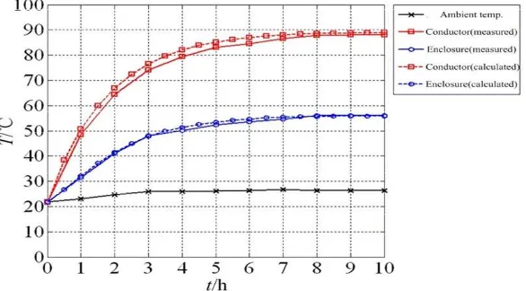
Table. 1 Dimensions and Materials of the GIL
Item Conductor Enclosure
Material A6063-T5 A6063-T5
Inner diameter (mm) 140 480
Outer diameter (mm) 180 504
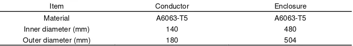
4.1. Temperature Variation of the GIL under Time Varying Ambient Temperature
Under the condition of no wind or solar radiation, the variation of GIL temperature in 10 hours at the current of 7300 A is illustrated in Figure 2. The initial temperature of the conductor and the enclosure is the same as the ambient temperature before the current is loaded. In the first 3 hours, an appreciable increase in the conductor and the enclosure is recognized. During the next 7 hours, the temperature rises slow down gradually and nearly come to a steady-state. Finally, the temperature rise of the conductor is 67 K and that of the enclosure is 34K. The temperature distributions inside the GIL at different times are illustrated in Figure 3. The maximum temperature occurs right above the conductor, while the minimum temperature at the bottom of the enclosure. The difference between the temperature distributions of the GIL after 6 hours is unobvious. The variation of the convective heat transfer coefficient on the enclosure surface is shown in Figure 4. The convective heat transfer coefficient increases rapidly in the first 2 hours and then reaches stability gradually.
4.2. Temperature Variation of the GIL under the Effect of Wind
Figure 2 Temperature variation of the GIL under time varying ambient temperature
Figure 3. Temperature distributions of the GIL at different times
Figure 4. Heat transfer coefficient variation under time varying ambient temperature
Figure 5. Temperature variation process for case of wind
Figure 6. Surface convective heat transfer coefficient variation for case of wind
Figure 6 gives the variation of the convective heat transfer coefficient on the enclosure surface. Noticeable variation is shown after exposing the GIL to the wind, and the coefficient is approximately proportional to the change of the wind velocity.
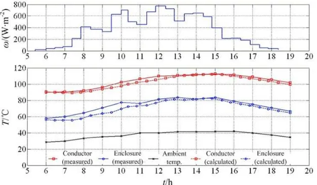
4.3. Temperature Variation of the GIL under the Effect of Solar Radiation
The temperature rises of the conductor and enclosure due to solar radiation after the current-induced temperature rise has leveled off are shown in Figure 7.
The temperature of the GIL rises with increasing radiation flux in the range of 0-770 W/m2. Moreover, the temperature of the enclosure is a little more sensitive to solar radiation than the conductor, and the maximum temperature rise of the conductor and the enclosure are 22.2 K and 26.3 K, respectively. The influence of the solar radiation over the temperature rise is evident and deserves special consideration for better thermal design of GIL.
5. Conclusion
In order to investigate the transient heat transfer characteristics of the GIL installed above ground, a finite-element model is established and appropriate boundary conditions were presented. Temperature variation process of the GIL under time-varying ambient temperature, wind velocity and solar radiation are described in detail, respectively. The calculated results correspond well with the tests results reported in the literature. The following conclusions are obtained:
- The good agreement between the calculated and tested results shows that the scheme using convective heat transfer boundary and heat flux boundary, respectively, in the model under the condition of wind and solar radiation is effective.
- When the time varying ambient temperature is only considered in the model, in the first 3 hours, the GIL temperature rises rapidly and gradually comes to the steady state in the next 7 hours. The convective heat transfer coefficient on the enclosure surface is deemed to be constant after the first 2 hours.
- The temperature of the enclosure is more susceptible to wind than the conductor because the outer surface convective heat transfer coefficient of the enclosure will be affected by wind directly.
- The temperature variations of the conductor and enclosure due to solar radiation are obvious and present the same tendency although the temperature of the enclosure is slightly more sensitive to solar radiation than the conductor.
References
[1] Benato R, Carlini E M, Mario C D. Gas-insulated transmission lines in railway galleries. IEEE Transactions on Power Delivery. 2005; 20(2): 704-709.
[2] Koch H, Schuette A. Gas insulated transmission lines for high power transmission over long distances. Electric Power System Research. 1998; 44(1): 69-74.
[3] Benato R, Dughiero F, Forzan M. Proximity effect and magnetic field calculation in GIL and in isolated phase bus ducts. IEEE Transactions on Magnetics. 2002; 38(2): 781-784.
[4] Wu X W, Shu N Q, Li H T. Thermal analysis in gas insulated transmission lines using an improved finite-element model. Telkomnika. 2013; 11(1): 458-467.
[5] Kuroyanagi Y, Toya A, Hayashi T. Construction of 8000A class 275kV gas insulated transmission line.
IEEE Transactions on Power Delivery. 1990; 5(1): 14-20.
[6] Volcker O, Koch H. Insulation co-ordination for gas-insulated transmission lines(GIL). IEEE Transactions on Power Delivery. 2001; 16(1): 122-130.
[7] Minaguchi D, Ginuo M, Itaka K. Heat transfer characteristics of gas-insulated transmission lines. IEEE Transactions on Power Delivery. 1986; PWRD-1(1): 2-9.
[8] Itaka K, Akari T, Hara T. Heat transfer characteristics of gas spacer cables. IEEE Transactions on
Power Apparatus and Systems. 1978; PAS-97(5): 1579-1585.
[9] Benato R, Dughiero F. Solution of coupled electromagnetic and thermal problems in gas-insulated transmission lines. IEEE Transactions on Magnetics. 2003; 39(3): 1741-1744.
[10] Chakir A, Sofiane Y, Aquelet N. Long term test of buried gas insulated transmission lines (GIL).
Applied Thermal Engineering. 2003; 23(13): 1681-1696.
[11] Chakir A, Souli M, Aquelet N. Study of a turbulent natural convection in cylindrical annuli of gas-insulated transmission lines 400 kV. Applied Thermal Engineering. 2003; 23(13): 1197-1208.
[12] Ho S L, Li Y, Lin X. Calculations of eddy current, fluid, and thermal fields in an air insulated bus duct system. IEEE Transactions on Magnetics. 2007; 43(4):1433-1436.
[13] Rajagopala K, Panduranga V, Lunavath H. Computation of electric field and thermal properties of 3-phase cable. Telkomnika. 2012; 10(2): 265-274.
[14] Anderson JD. Computational Fluid Dynamics: The Basics with Applications. New York: McGraw-Hill. 1995: 452-455.
[15] Eteiba M B, Aziz M M A, Shazly J H. Heat conduction problems in SF6 gas cooled-insulated power