UNIVERSITI TEKNIKAL MALAYSIA MELAKA
Design and Validate Passive Automotive Engine Mount System
This report submitted in accordance with requirement of the Universiti Teknikal Malaysia Melaka (UTeM) for the Bachelor Degree of Engineering Technology
(Automotive Technology) (Hons.)
by
AHMAD AIZAT AQMAL BIN HISHAMUDDIN B071110372
891208 – 13 – 5847
TAJUK: Design and Validate Passive Automotive Engine Mount System
SESI PENGAJIAN: 2014 / 2015 Semester 2
Saya AHMAD AIZAT AQMAL BIN HISHAMUDDIN
mengaku membenarkan Laporan PSM ini disimpan di Perpustakaan Universiti Teknikal Malaysia Melaka (UTeM) dengan syarat-syarat kegunaan seperti berikut:
1. Laporan PSM adalah hak milik Universiti Teknikal Malaysia Melaka dan penulis. 2. Perpustakaan Universiti Teknikal Malaysia Melaka dibenarkan membuat salinan
untuk tujuan pengajian sahaja dengan izin penulis.
3. Perpustakaan dibenarkan membuat salinan laporan PSM ini sebagai bahan pertukaran antara institusi pengajian tinggi.
4. **Sila tandakan ( )
SULIT
TERHAD
TIDAK TERHAD
(Mengandungi maklumat yang berdarjah keselamatan atau kepentingan Malaysia sebagaimana yang termaktub dalam AKTA RAHSIA RASMI 1972)
(Mengandungi maklumat TERHAD yang telah ditentukan oleh organisasi/badan di mana penyelidikan dijalankan)
Alamat Tetap:
NO.116 LOT4327 LRG DESA ILMU
22A2 PH 15 TMN DESA ILMU 94300
KOTA SAMARAHAN, SARAWAK.
Tarikh: ________________________
Disahkan oleh:
UNIVERSITI TEKNIKAL MALAYSIA MELAKA
BORANG PENGESAHAN STATUS LAPORAN PROJEK SARJANA MUDA
Cop Rasmi:
i
DECLARATION
I hereby, declared this report entitled “Design and Validate Automotive Passive Engine Mount Engine” is the results of my own research except as cited in
references.
Signature :
Author’s Name : AHMAD AIZAT AQMAL BIN HISHAMUDDIN
ii
APPROVAL
This report is submitted to the Faculty of Engineering Technology of UTeM as a partial fulfillment of the requirements for the degree of Bachelor of Engineering Technology (Automotive Technology) (Hons.). The member of the supervisory is as follow:
iii
ABSTRAK
iv
ABSTRACT
v
DEDICATION
vi
ACKNOWLEDGEMENT
First and Foremost, I would like to express my greatest appreciation and thanks to Universiti Teknikal Malaysia Melaka for giving me the opportunity to undergo my final year “Projek Sarjana Muda” under the supervision of ENGR. Mr. Muhamad Hafiz Bin Harun. A special thank you also goes to my supervisor ENGR. Mr. Muhamad Hafiz Bin Harun and my co-supervisor Mr. Fauzi Bin Ahmad for his dedication and guidance during the period of undergoing my project and also to master student Mohamad Zaharudin Bin Sariman for his guidance.
Last but not least, I want to thank my beloved mother and beloved father and Haji
Ariffin’s whole family members for their encouragement and support as well as to all
vii
List Abbreviations, Symbols and Nomenclatures
CHAPTER 2: LITERATURE REVIEW 3
2.1 Introduction 3
2.2 Types of Engine Mount 4
2.2.1 Passive Hydraulic Engine Mount 6
2.2.1.1 The Adaptive Hydraulic Mount 9 2.2.1.1.1 Property Characterization of
Hydraulic Mount 12
2.2.1.1.2 Characterization of Hydraulic
Mount Properties 12
2.2.1.2 Elastomeric Mount 13
2.2.1.3 Hydraulic (fluid) Mount 16
2.2.2 Active Engine Mounting 20
2.2.3 Semi-Active Engine Mounting 24
2.2.3.1 Magnetorheological Fluid – Elastomers 27
2.3 Operation of Engine Mounting 28
2.3.1 Dependency of Location of the Notch
And Peak Frequencies on the Mount Parameters 32 2.3.2 Dependency of Location of the Notch
CHAPTER 3: METHODOLOGY 40
CHAPTER 4: RESULT AND DISCUSSION 54
4.1 Introduction 54
viii
LIST OF TABLE
TABLE TITLE PAGES
2.1 Numerical Values of The Parameters For Fluid Inn Each Inertia Track
31
3.1 Block Diagram/Symbols 45
3.2 Nomenclature of The Include Parameters 46
3.3 Simulink Model Parameters 48
ix
LIST OF FIGURE
FIGURE TITLE PAGE
2.1 Different Engine Mount Design 3
2.2 Engine Mounting System Technology Road Map
2.7 Operation of Adaptive Hydraulic Mount 10
2.8 A Physical Model of An Elastomeric Mount 13 2.9 Mechanical Model of An Elastomeric Mount 13
2.10 Typical Elastomeric Mounts 14
2.11 Typical Rear Mount Installation 14
2.12 Dynamic Stiffness of An Elastomeric Mount 15
2.13 Physical Model of Hydraulic Mount 16
2.14 Mechanical Model of A Hydraulic Mount 17
2.15 Dynamic Stiffness of A Hydraulic Mount 18
2.16 Physical Model of A Hydraulic Mount 19
2.17 Mechanical Model of An Active Elastomeric Mount
21
Mount
2.19 Dynamic Stiffness of An Active Hydraulic Mount
23
2.20 Mechanical Model of Semi-active Hydraulic Mount
26
2.21 Regular and Inertia Track Mount of Hydraulic Mount
3.4 Experimental setup description 51
3.5 Accelerometer Sensor 52
3.6 MCP Electronics (Voltage Meter) 52
4.1 Free Body Diagram Engine Mounting System (EMS)
56
4.2 Experimental setup description 59
4.3 Actual Test Rig with Unbalance Load Motor 59
4.4 MCP Electronics (Voltage Meter) Setup 60
4.5 Setup Accelerometer Sensor at the Mounting 60 4.6 Comparison between the simulation results
with the experiment results for the vertical acceleration with frequency input 9 Hz.
61
4.7 Comparison between the simulation results with the experiment results for the pitch moment acceleration with frequency input 9 Hz.
63
48 Comparison between the simulation results with the experiment results for the roll moment acceleration with frequency input 9 Hz.
x
Zs - Engine Unit Displacement
Zu - Chassis Unit Displacement
Żs - Engine Unit Velocity
Żu - Chassis Unit Velocity
- Engine Unit Acceleration
Ksr - Right Spring Constant
Zsf - Front Engine Unit Displacement
Zsrr - Rear Engine Unit Displacement
Zsr - Right Engine Unit Displacement
Zsl - Left Engine Unit Displacement
Zuf - Front Chassis Unit Displacement
Zurr - Rear Chassis Unit Displacement
Zur - Right Chassis Unit Displacement
Zul - Left Chassis Unit Displacement
Żsf - Front engine unit velocity
Żsrr - Rear engine unit velocity
Żsr - Right engine unit velocity
Żsl - Left engine unit velocity
Żuf - Front chassis unit velocity
Żurr - Rear chassis unit velocity
Żur - Right chassis unit velocity
Żul - Left chassis unit velocity
- Pitch acceleration
Α - Roll angle
- Roll rate
1
1.1 Background
A car engine is connected with an engine mount on the car frame. An engine mount are usually made of rubber and metal. The metal portions are connected to the engine on the one side and to the frame on the other. The rubber is between an apparatus for controlling relative movement and engine mount housing to provide some flexibility. Now-a-days, most of the newer cars are used slightly different mounts. However, there purpose is still the same.
Generally, hydraulic engine mounts are used in aerospace and automotive application for the purpose of cabin noise and vibration reduction. The dynamic stiffness will be smaller at certain frequency than the static stiffness, cabin vibration and noise reduction. All the hydraulic mount design parameters are selected very carefully. This frequency is referred as notch frequency and it is provided at that frequency.
In this paper, passive hydraulic engine mounts will be modelled. An improved decoupler control is introduced that the mechanism steady state behaviour does not noticeably affect, but start up and transient response improves. Hydraulic mount design more effective and it is tuneable and the mechanism of decoupler design will be smaller and lighter.
2
1.2 Project Problem Statement
1. The compatibility an engine mounts system to run on a test rig.
2. The proper method is needed to solve the dynamics vibration occurs on the test rig and the engine mounting.
1.3 Project Objective
1. To analyze engine mount system using a 3-DOF equation. 2. To model the engine mount system using MATLAB Simulink. 3. To validate the engine mount model with engine mount test rig.
1.4 Scope of Project
My research project will focus primarily on the functions of the passive engine mounting to be implemented on a test rig. An engine that attaches to unbalance load will be placed on a test rig. There will be four sensors that will be attached to the test rigs to detect the vibration, noise and harshness that is caused by motor or any mechanism of the engine parts. Then, the result obtained from MATLAB Simulink into the sensor will be applied.
1.5 Approach
My proposed report will begin with a brief review of the engine mounting. The report will then discuss how the passive engine mounting function or operate as a safety mechanism to be implemented on the vehicle’s chassis.
1.6 Result Expectation
1. Engine mount system using 3-DOF equation will be analyzed.
2. Manage to model passive engine mount system.
3
2.1 Introduction
(a) (b)
(c) (d)
(e) (f)
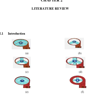
Figure 2.1: Different Engine Mount Designs. (a) Basic design (b) Two arm design (c) Three arm design (d) Four arm design (e) Filler arm design (f) Four arm symmetry design (Anynomous,ND)
Now-a-days, most of the cars are used slightly different types of design of the engine mounts as shown as in the Figure 2.1. However, the function and purpose is still the same. To give the driver and the passenger the comfort while experiencing the driving moment.
4
2.2 Types of Engine Mounts
Figure 2.2: Engine mounting system technology road map (Anynomous,ND)
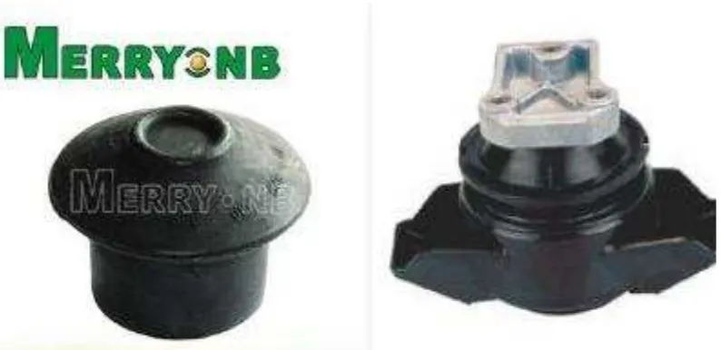
Figure 2.3: Rubber Mount (On the left) and Hydro Mount (On the right) (Anynomous,ND)
EMS
Passive
Active
Rubber Hydro-Mount
5 In Figure 2.2 shows that a system technology road map of engine mounting. Commonly an engine mounting looks like as shown in figure 2.3. Usually, a drivetrain car consists of the engine and transmission. The engine makes up a substantial bulk of a car’s weight, and where and automobile manufacturer decides to mount the engine directly impacts the vehicle’s performance. The position of the engine affects performance by setting the car’s moment of inertia, which is a physical property that determines, among other things, how quickly a car can turn (ehow.com, 2010). Car engine mounting are divided into 3 parts;
i. Front Mounted: Car manufacturers can mount a car’s engine in two ways. Front-mounted engines will be placed on in front or directly over the forward axle. A front-mid-mount is placed on the engine behind the front axle.