CHAPTER 1
INTRODUCTION
1.1 Introduction
High-quality digital tachometers are incorporated into servo,mechatronic,
robotic and precision production systems for the calculation of accurate,
high-bandwidth, digital velocity information.The M/T-type tachometer and the related
constant sample-time digital tachometer (CSDT) have been shown to perform
well in many such systems. However, sensor no ideality can introduce very
significant errors into the tachometer output. In this paper, it is shown that
performance can be greatly improved(i.e., the noise present in the velocity signal
significantly reduced) by oversampling the counter values used for velocity
calculation. The counting and oversampling operations inherent to the
oversampled CSDT (OCSDT) are implemented using a field-programmablegate
array (FPGA). The design of the digital circuitry is described in detail, with
particular emphasis on the circuits requiredfor implementation and control of the
2
processor (DSP). Besides implementing some division-based calculations to
generate a velocity word, the DSP can carry out other measurementand control
functions, as required by the overall system. Simulationstudies and experimental
results are used to highlight the advantagesof the over-sampling technique.
Tachometers or rev counters on automobiles, aircraft, and other vehicles
show the rate of rotation of the engine's crankshaft, and typically have markings
indicating a safe range of rotation speeds. This can assist the driver in selecting
appropriate throttle and gear settings for the driving conditions. Prolonged use at
high speeds may cause inadequate lubrication, overheating (exceeding capability
of the cooling system), exceeding speed capability of sub-parts of the engine (for
example spring retracted valves) thus causing excessive wear or permanent
damage or failure of engines. This is more applicable to manual transmissions
than to automatics. On analogue tachometers, speeds above maximum safe
operating speed are typically indicated by an area of the gauge marked in red,
giving rise to the expression of "redlining" an engine — revving the engine up to
the maximum safe limit. The red zone is superfluous on most modern cars, since
their engines typically have a rev limiter which electronically limits engine speed
to prevent damage. Diesel engines with traditional mechanical injector systems
have an integral governor which prevents over-speeding the engine, so the
tachometers in vehicles and machinery fitted with such engines sometimes lack a
redline.
In vehicles such as tractors and trucks, the tachometer often has other
markings, usually a green arc showing the speed range in which the engine
produces maximum torque, which is of prime interest to operators of such
vehicles. Tractors fitted with a power take off (PTO) system have tachometers
showing the engine speed needed to rotate the PTO at the standardized speed
required by most PTO-driven implements. In many countries, tractors are
required to have a speedometer for use on a road. To save fitting a second dial,
the vehicle's tachometer is often marked with a second scale in units of speed.
3
one gear that is practical for use on-road, this is sufficient. Tractors with multiple
'road gears' often have tachometers with more than one speed scale. Aircraft
tachometers have a green arc showing the engine's designed cruising speed
range.
In older vehicles, the tachometer is driven by the RMS voltage waves
from the low tension (LT) side of the ignition coil, while on others (and nearly
all diesel engines, which have no ignition system) engine speed is determined by
the frequency from the alternator tachometer output. This is a special circuit
inside the alternator to convert from rectified sine wave to square wave, and the
electrical potential difference is directly proportional to engine speed.
Tachometers driven by a rotating cable from a drive unit fitted to the engine
(usually on the camshaft) also exist - usually on simple diesel-engine machinery
with basic or no electrical systems. On recent EMS found on modern vehicles,
the signal for the tachometer is usually generated from an ECU which derives the
information from either the crankshaft or camshaft speed sensor.
The taco will measure RPM of an R/C helicopter rotor using a shutter
effect by rotating a disc at a known RPM and displaying the result on a LCD
screen. The user looks through a “view hole” and attempts to stop the blades
with the shutter speed control. When the disc RPM matches the rotor RPM, the
rotor will look like it’s not rotating. It’s a very simple concept and works very
well for this application. The memory button when pressed will take a “snap
shot” of the RPM at that moment and display it on the screen. This project
requires some fairly good soldering skills and some fabrication ability is helpful.
The purpose of this project is to develop an angular speed detection system using
a special Infra-Red sensor (IR) where it can detect black and white color and give
a small differences voltage signal when the shaft motor was rotating. The black
and white color will put at the shaft motor. When the shaft motor is rotated, the
emitter IR sensor will emit infrared continuously and detect the color changes
depends on setting or fixed time that will be programmed at microcontroller
4
This colors changing will generate a differences voltage. Usually, the
microcontroller only recognizes digital input which is 0V and 5V. If the infrared
reflected is less, the receiver would probably produce 2V or 3V and
microcontroller is unable to deal with these analog values. So, the comparator
(LM324) is used to solve this problem. By using the comparator LM324, the
output voltage from IR receiver will compare to an input voltage through a
variable resistor. This comparator able to compare for both input voltage and
generate either 0V or 5V where it can connect to microcontroller. Lastly, the
output voltage from microcontroller will display using LCD (Liquid Crystal
Display) 8 x2LCD screen
1.2 Objectives
There are several objectives that are to be achieved at the end of the project
which includes:
i. To design an intelligent system of automatic fish feeder using PIC
microcontroller.
ii. To learn about the art of programming in C language.
iii. To combine together all hardware skills, electronic knowledge with some
software development in building this project.
iv. To make sure that this tachometer became small and can be used in a
small area.
v. To explore the application of infrared sensor at industry.
5
1.3 Problem Statement
The problem in this project is to generating the output in digital value at
LCD display where the sensor has detected average 100µA – 10mA .Beside that the speed of rotating motor need to control to make sure the output can be
measure depends on the setting time. The project also have improve the design to
make it became more flexible in all area.
The screen updates the RPM every 1 second since that’s how long it
reads the sensor. The longer time to read the sensor, the more accurate the RPM
is. There is a trade off due to the math in step 3. If the sensor longer, the
resolution goes higher however the screen update gets longer which can be a
pain. If you read the sensor shorter for example perhaps it’s only .5 seconds,
then you get a fast screen update but the RPM is low resolution which causes the
RPM to count by 50’s. I tried to get the best of both worlds. Reading the sensor
for 1.5 seconds, the RPM will count by 20’s which is pretty good. It’s stable and
does not jump all over the place.
The reason I used three slots instead of one was to slow down the “real”
RPM of the wheel. I tried it with one slot and the wheel had to physically spin at
3000 RPM to read a 3000RPM heli rotor. This made the tach vibrate and it was
very noisy. Three slots caused the wheel to spin at 1/3rd of its original speed and
it was very quiet. When the tach is reading a rotor RPM of 3000, the wheel
6 1.4 Scope of Work
As to ensure the completion of project achieves the stated objectives, the
project shall be completed within these scopes:
i. To built an IFF system that is suitable for;
ii. The input power used 12V-15 V
iii. The rotation motor speed will measured aroud 100-2000 rev/m and ±
10% tolerence.
iv. The out put will be dispay in LCD (2x8 display)
v. The input current that supply to infrared sensor is around 100µA –
7
CHAPTER 2
LITERATURE REVIEW
2.1Introduction
This chapter is discussing about previous research in tachometer related
on the project. There are two previous projects that will be discussed in this
chapter.
2.2 Tachometer (toothed rotor tachometer detection.
The infrareds sensor is widely used in industries for scanning bar code
and detecting material. The research in measuring position recently becomes more
important. The measurement of position for rotating and linearly translating parts is a
key requirement in automation. The instrument that measuring rotating part called
tachometer. There is lots of tachometer with different type of sensing technique but they
have disadvantages. Among disadvantages are managing the sensor required time and
lack of precision in measurement. The following cases are about tachometer and their
disadvantages.
A tachometer is a device to measure speed of rotating shaft in the angular speed
which mean in revolutions per minute. The tachometers are widely used in industries to
8
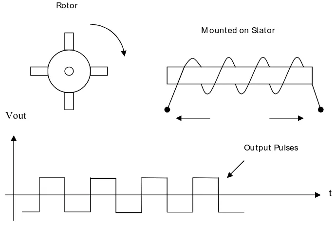
use to sense the speed of rotating shaft. For example, toothed – rotor tachometer which
used several ferromagnetic tooth on its rotor. Then, a permanent magnet with a coil
wrapped around it, is placed in the motor stator. The changing of magnetic field strength
will induce a voltage. For every rotor tooth one voltage pulse id\s produced. The input
voltage pulse will be converted into frequency as an output signal. The toothed – rotor
tachometer has disadvantage because it’s fix to the rotor of the motor and reassemble the
[image:23.595.168.512.257.488.2]motor required.
Figure 2.1: Toothed-rotor tachometer detection
The other type of tachometer that commonly used in industrial control
application is rotary encoder. This instrument used a photo sensor and a disc which will
be montage on the rotating shaft. The rotating disc has a narrow radial slit which allows
light from LED go through the disc. Several photodiodes which are placed behind the
slit will detected the light and produced modulated light beam in form of voltage pulses.
This voltage signal will be amplified and generated into digital waveforms suitable for
subsequent process.
Vout
t
Rotor
M ounted on Stator
9
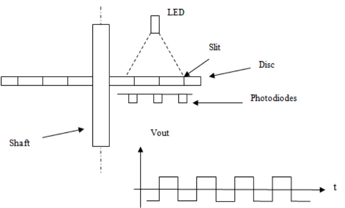
The other type of tachometer that commonly used in industrial control
application is optical rotary encoder. This instrument used a photo sensor and a disc
which will be montage on the rotating shaft. The rotating disc has a narrow radial slit
which allows light from LED go through the disc. Several photodiodes which are placed
behind the slit will detected the light and produced modulated light beam in form of
voltage pulses. This voltage signal will be amplified and generated into digital
[image:24.595.181.528.279.488.2]waveforms suitable for subsequent process.
Figure 2.2: Optical Rotary Encoder
The disc of the optical rotary encoder has to be assembly perpendicular to the
rotating shaft of the motor. It must be tight up to the shaft to be reducing disc shaking
during rotating that can be effect the detection of light beam. Furthermore, the disc has a
weight and that can be affect minor error to the result. At this point of view, the infrared
tachometer sensor has advantage compared to the optical rotary encoder.
The infrared tachometer sensor needs only a reflector which have black and