i
PARKING CONTROL SYSTEM USING PLC
SITI NOR AIN BT MAT ZIN
This report is submitted in partial fulfillment of the requirements for the award of Bachelor of Electronic Engineering (Industrial Electronics) with Honors
Faculty of Electronic and Computer Engineering Universiti Teknikal Malaysia Melaka
ii
UNIVERSTI TEKNIKAL MALAYSIA MELAKA
FAKULTI KEJURUTERAAN ELEKTRONIK DAN KEJURUTERAAN KOMPUTER
BORANG PENGESAHAN STATUS LAPORAN PROJEK SARJANA MUDA II
Tajuk Projek : PARKING CONTROL SYSTEM USING PLC
Sesi
Pengajian : 2009/2010
Saya SITI NOR AIN BT MAT ZIN
mengaku membenarkan Laporan Projek Sarjana Muda ini disimpan di Perpustakaan dengan syarat-syarat kegunaan seperti berikut:
1. Laporan adalah hakmilik Universiti Teknikal Malaysia Melaka.
2. Perpustakaan dibenarkan membuat salinan untuk tujuan pengajian sahaja.
3. Perpustakaan dibenarkan membuat salinan laporan ini sebagai bahan pertukaran antara
institusi pengajian tinggi.
4. Sila tandakan ( √ ) :
SULIT*
(Mengandungi maklumat yang berdarjah keselamatan atau kepentingan Malaysia seperti yang termaktub di dalam AKTA RAHSIA RASMI 1972)
TERHAD* (Mengandungi maklumat terhad yang telah ditentukan oleh
organisasi/badan di mana penyelidikan dijalankan)
TIDAK TERHAD
Disahkan oleh:
__________________________ ___________________________________
(TANDATANGAN PENULIS) (COP DAN TANDATANGAN PENYELIA)
Alamat Tetap:248-1,JALAN BACHANG , BATU BERENDAM, 75350 MELAKA
iii
“I hereby declare that this report is the results of my own work except for quotes as cited in the reference.”
Signature : ………
Author : SITI NOR AIN BT MAT ZIN
iv
“I hereby declare that I have read this report and in my opinion this report is sufficient in terms of the scope and quality for the award of Bachelor of Electronic Engineering
(Industrial Electronics) With Honors”
Signature : ………
Supervisor’s name : MDM. NURMALA IRDAWATY BINTI HASSAN
v
Dedicated to my parents, Mat Zin b Ahmad and Rahmah bt Md Taib ,my siblings, and
vi
ACKNOWLEDGEMENT
First of all, I would like to thank God for his blessing, and I also want to express my deepest gratitude to my supervisor Ms.Nurmala Irdawaty Bt Hassan for support and guidance throughout this project running and completion of this report.
My deepest appreciation also goes out to Mrs. Siti Huzaimah bt Husin who gave me many needed support, encouragement and help throughout my project’s improvement, Ms. Nor Farah Hidayah bt Badul Zaman which is my project’s partner who struggling with me exploring this scope. Not to forget, thanks to my family and fellow friends who encouraged me.
vii
ABSTRACT
viii
ABSTRAK
Tujuan projek ini itu adalah bagi membangunkan satu sistem tempat letak kereta yang dapat menyelesaikan masalah-masalah mengenai kekosongan tempat letak kereta dengan kecekapan yang lebih tinggi melalui Programmable Logic Controller (PLC). Objektif projek ini adalah untuk membina sebuah prototaip yang berfungsi sepenuhnya, dapat digunakan dan tepat mengikut jumlah kekosongan .Sistem tempat letak kereta ini mampu mengesan dan mengira kenderaan keluar masuk pada tempat letak kereta dan pada masa yang sama juga, setiap tempat letak kenderaan akan menyediakan beberapa penunjuk untuk menunjukkan kekosongan kawasan tempat letak. Tambahan lagi, penyelidikan ini juga termasuk mekanisme tentang bagaimana penunjuk ‘FULL’ itu akan diaktifkan oleh satu pengesan logam yang dipilih. Sebagai satu penunjuk awal untuk kekosongan tempat letak kenderaan, sebuah skrin akan diletakkan di depan Entrance / Exit sebagai satu cara untuk memvisualkan dan menjadi perantara maklumat
ix
CONTENTS
CHAPTER TITLE PAGE
PROJECT TITLE i
REPORT STATUS VERIFICATION FORM Ii
STUDENT’S DECLARATION iii
SUPERVISOR’S DECLARATION iv
DEDICATION v
ACKNOWLEDGEMENT vi
ABSTRACT vii
ABSTRAK viii
CONTENTS ix
LIST OF TABLES xii
LIST OF FIGURES xiii
LIST OF ABBREVIATIONS xv
LIST OF APPENDICES xvi
I INTRODUCTION
1.1 Project Introduction 1
1.2 Project Objectives 2
1.3 Problem Statement 2
x
II LITERATURE REVIEW
2.1 Control System 4
2.1.1 Elements of Control System 5
2.1.2 Traditional Control System 6
2.2 Programmable Logic Controller (PLC) 7
2.2.1 Historical Background of PLC 9
2.2.2 Development of PLC 10
2.2.3 Hardware Design of PLC 11
2.2.4 Input Adjustment Interface 13
2.3 PLC Programming 14
2.3.1 Basic Ladder Diagram 14
2.3.2 Examples of Ladder Diagram 14
2.3.3 Logic Instructions (Mnemonics) 17
2.4 Types of PLC 19
2.5 PLC Communication 19
2.5.1 Serial Communication –RS 232 20
2.5.2 The 20 mA Current Loop 20
2.5.3 RS422 20
2.6 PLC Selection 21
2.6.1 Comparison between PLC and Relay 22
2.6.2 Comparison between PLC and Computer 23
2.7 PLC comparison 23
2.7.1 PLC comparison between other parking system 24
III METHODOLOGY
3.1 Project Methodology 25
xi
IV RESULTS AND DISCUSSION 32
4.1 First Phase Result: The Development of PLC 29 4.2 Second Phase Result: Project Result and Analysis 34
V CONCLUSION
5.1 Conclusion 56
5.2 Project limitation 57
5.3 Recommendation 58
xii
LIST OF TABLES
NO. TITLES PAGE
2.4.1 Classification of PLC 19
2.7.1 Comparison between other project 24
xiii
LIST OF FIGURES
NO. TITLES PAGE
2.1.1 Block diagram of control system. 5
2.1.2 Example of top view of relay 6
2.2.1 Example of PLC system using Discrete Input 8
2.2.2 Basic elements of PLC controller 9
2.2.4.1 Adjustment interface 13
2.3.2.1 Basic ladder diagram 14
2.3.2.2 Ladder diagram for bell. 15
2.3.2.3 Ladder diagram for a garage parking system 16
2.3.3.1 Programming Console (Type: OMRON) 17
2.3.3.2 PLC Trainer (OMRON) with console attach to it 18
3.1 Flow Chart of Methodology 26
3.2 Flow chart of general operation of parking system 28 4.1.1 Ladder diagram of initial condition at parking lot(RUN mode) 30 4.1.2 The mnemonic code of ladder diagram 31
4.1.3 When a first sensor activated 32
4.1.4 When a RESET switch is activated 33
4.2.1 Designed Program for lot Parking 34
xiv
4.2.3 Designed Program for Entrance & Exit Parking System 39 4.2.4 Incomplete construction of Program for Entrance & Exit
Parking System
40
4.2.5 System ON-Start 41
4.2.6 PARKING LOT 1, Sensor Lot1 ON 42
4.2.7 PARKING LOT 2, Sensor Lot2 ON 43
4.2.8 PARKING LOT 3, Sensor Lot3 ON 44
4.2.9 PARKING LOT 4, Sensor Lot4 ON 45
4.2.10 PARKING LOT 5, Sensor Lot5 ON 46
4.2.11 PARKING LOT 6, Sensor Lot6 ON, indicator FULL activated 47
4.2.12 Output PLC Trainer 48
4.2.13 Overall Picture 49
4.2.14 the connection of four 7 Segments 50
4.2.15 Circuit of 7 Segment 51
4.2.16 Connection of FULL circuit using RELAY 24V DC with 7 Segments
52
4.2.17 Reference on how the connection of LED 24V legs 52
4.2.18 Overall process result 53
4.2.19 The Equipments and Software used 54
xv
LIST OF ABBREVIATION
PLC - Programmable Logic Controller
ROM - Read-Only-Memory
RAM - Random-Access-Memory
EPROM - Erasable and Programmable Read-Only-Memory
EEPROM - Electrically Erasable and Programmable Read-Only-Memory
CPU - Central Processing Unit
xvi
LIST OF APPENDICES
NO. TITLES PAGE
A PLC CONNECTION 60
B FARNELL-SEVEN SEGMENT DATASHEET 62
1
CHAPTER I
INTRODUCTION
1.1 Project Introduction
The conventional car park system normally just have some signboard of direction of vehicles need to follow. It does not have any display panel and it cannot show the total vacancy of parking lot in the parking area. The drivers has take risk to seek either there are any vacancy or not. By developing a parking system that includes the availability of vacancy display can help the drivers as a user to shorter their searching time. This PLC and VB based Parking system is a electronic applications will improving the conventional parking system by using suitable sensor and display panel
2
1.2 Project Objectives
1.2.1 To build a system based on Programmable Logic Controller (PLC) based parking system.
1.2.2 To design a system that can detect any changes of number of available parking space and inform the drivers through Indicators.
1.2.3 To build a mini prototype of this parking system.
1.3 Problem Statement
3
1.4 Scope of Work SOFTWARE
i. Counting the free parking space
The system must able to calculate the number of available parking space. A sensor will be used to sense a vehicle and will be an input to the counting program. Increasing or decreasing the total number of free parking space (output) is depends on the number of car entering and leaving the parking area.
ii. Display number of available parking space and display the info of available parking space through a screen.
The number of free parking space will be displayed on a 7 segment as the output .The7-Segments will be displayed at the main Entrance/Exit. It also need to ensure the hardware can trigger the Visual Basic to a screen that will display the total vacancy of parking lots,
iii. Build a parking system that can operate in real time.
4
CHAPTER II
LITERATURE REVIEW
2.1 CONTROL SYSTEM
In general, control system is a collection of electronic devices and equipment which are in place to ensure the stability, accuracy and smooth transition of a process or a manufacturing activity [1].
5
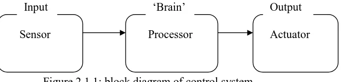
[image:21.595.166.515.149.233.2]2.1.1 Elements of Control System
Figure 2.1.1: block diagram of control system.
Normally, a control system consists of three sections which is input, processing and output of the system.Input section or also known as the input signals for a system, usually come from various sensors that convert physical quantities into electrical signal. Examples of these inputs are push-button switch, limit switch or proximity sensors and etch. The input signal is vary depending on the sensors used; it may be represents by an on/off (binary) or a continuous (analog)
For processing section, the automatic control will produce the necessary output signals in accordance the control plan into the processor. This control plan system can be implemented either hard wired control system or programmable logic control system. The disadvantages if hard-wired control system, the control function is fixed permanently when the system components are connected together, while, in a programmable logic control system having the function programmed and stored within a memory unit. This program can be change or modify whenever necessary.
The last section of a control system is the output system that produces the desired output. It converts signals from the control system into another necessary quantity. A pneumatic signal for example, converts signals into linear motion. Other output example of output devices is solenoid, stepping motor and speaker [6].
Sensor Processor Actuator
6
2.1.2 Traditional Control System (Relays).
Relays are used in many modern control systems, as it is an electrical switch with a high current rating that is indirectly operated by a low control current.
[image:22.595.230.438.319.485.2]Small relays often come packaged in clear, rectangular, plastic cases, which had led to the name ice cube relay to be commonly applied to them. These so-called "ice cube" relays have either eight or eleven pins protruding from the bottom, allowing them to be plugged into a special socket for connection with wires in a circuit:
Figure 2.1.2 : Example of top view of relay [8].
A typical relay control system consists of several hundred or thousand switching contacts, which makes designing becomes a considerable tasks. Even for a simple tasks the number of relays used result in a large control panel, because each relay can only provide a small number of contacts relay coils, example less than 10. The function of relay can only described and designed on a relay circuit diagram which illustrates the interconnection of all electrical contacts and relay coils, together with information of the electrical and mechanical construction of the system.
re-7
wiring of the system necessary. Another disadvantage of this system is the control system is cost, speed and reliability. Relay is still being used extensively as output devices (actuator) on other types of control system, being suitable for the conversion of small control signals to higher-current/higher-voltage driving signals.
2.2 PROGRAMMABLE LOGIC CONTROLLER (PLC)
8
Figure 2.2.1 : Example of PLC system using Discrete Input [4].
![Figure 2.1.2 : Example of top view of relay [8].](https://thumb-ap.123doks.com/thumbv2/123dok/619516.74568/22.595.230.438.319.485/figure-example-view-relay.webp)
