JSS F
OCUSI
SSUE ONN
ANOCARBONS FORE
NERGYH
ARVESTING ANDS
TORAGEDevelopment of High Performance Electrochemical Capacitor:
A Systematic Review of Electrode Fabrication Technique Based
on Different Carbon Materials
Nor Syafira Abdul Manaf, Mohd Shahril Amin Bistamam, and Mohd Asyadi Azam∗,z
Faculty of Manufacturing Engineering, Universiti Teknikal Malaysia Melaka (UTeM), Hang Tuah Jaya, Durian Tunggal, Melaka 76100, Malaysia
Increasing demand for energy requirement has attracted considerable attention among researchers to develop efficient energy storage device. Among energy storage devices, electrochemical capacitor (EC) has great potential for its capability to deliver more power than batteries and store more energy than conventional capacitors. The electrode or active material is the most crucial factor in determining the device properties. Recently, carbon based materials play significant roles as electrode materials and possesses remarkably significant achievements toward the development of sustainable energy storage applications. Electrode fabrication technique is another important factor to be considered. Hence, this article reviews the electrode fabrication techniques for EC based on different types of carbon as electrode materials, and their EC performances measured by techniques such as cyclic voltammetry and charge discharge characteristics are also discussed.
© 2013 The Electrochemical Society. [DOI:10.1149/2.014310jss] All rights reserved.
Manuscript submitted July 23, 2013; revised manuscript received September 3, 2013. Published September 10, 2013.This paper is part of the JSS Focus Issue on Nanocarbons for Energy Harvesting and Storage.
Background.—Nowadays, sustainable energy sources are impor-tant and have been utilized in many applications due to the decreasing availability of fossil fuels.1Renewable resources such as solar2and wind power3have the ability to generate electricity, and thus offers high potential for future energy demands. However, these kinds of sources provide limited energy consumption due to the continuous utilization of energy for up to 24 h a day. To overcome this matter, energy storage devices are introduced to achieve an effective level in the cycle of renewable energy sources.4 A lot of efforts have been put in researching and developing more efficient energy storage sys-tem that is more novel, low-cost, environmentally friendly, and better performance to meet the market requirement.5 Batteries, fuel cells, and electrochemical capacitors (ECs) are among those devices for the newly introduced electrochemical energy storage and conversion.6
ECs provide the necessary power for acceleration and additionally allow for recuperation of brake energy in hybrid electric vehicle.7–9 Moreover, ECs are constructed and/or assembled much like a bat-tery and their function is also similar. Function of both batteries and ECs are to store electrical charges. In a basic form, ECs con-sist of two symmetric electrodes immersed in an electrolyte with a dielectric separator between the electrodes. ECs are generally classi-fied into three types, which are electrochemical double layer capaci-tor (EDLC), pseudocapacicapaci-tor, and hybrid capacicapaci-tor.8,10,11The general principle and mechanism of these types of ECs will be discussed in this manuscript.
Commonly, fabrication of ECs consists of electrode preparation and cell assembly. Studies about the electrode fabrication technique of ECs are important to successfully produce high performance ECs. Notably, selection of electrode materials has become an essential factor to verify the properties and performances of ECs.12Also, simple procedures to fabricate ECs will reduce the fabrication complexity and reduce the number of process steps in fabricating the device.13 Typically, cyclic voltammetry (CV) and charge discharge analysis are commonly conducted to determine electrochemical performance of ECs. Fabrication of high performance ECs with high operating voltage, high energy density and power delivery, and longer charge discharge cycle lifetimes must be developed to significantly enhance the potential of energy storage technology.14
Advantages of EC.—As we know, batteries are the most common energy storage device, batteries have short life cycle
∗
Electrochemical Society Active Member.
zE-mail:[email protected]
and powers of batteries are below than 100 W kg−1.15 How-ever, batteries are useful and suitable for energy storage over long time application more than 100 s, while conventional ca-pacitors for short time storage less than 0.01 s. Meanwhile, conventional capacitor possesses high power density more than 103 kW kg−1and also long life cycle, but their energy density is low about 70 mWh kg−1. Hence, ECs have been developed for the cases which required large energy density (Wh kg−1), high power density (W kg−1), and long life cycle, more than 100,000.15
As compared to other energy storage devices, ECs have some ad-vantages such as high power density, high energy density, long life cycle, fast charge and discharge rate, a wide thermal operating range, low weight, flexible packaging, and low maintenance.16–21 Accord-ing to Pandolfo et al., ECs have the capability to rapidly charge and discharge at power density exceeding 1 kW kg−1.22Also, ECs show intermediate energy storage devices that bridge the critical perfor-mance gap between higher energy density of battery and high power density of conventional capacitor.23–25
Principle and mechanism of EC.—ECs are generally categorized into three different types which are electrical double layer capaci-tors (EDLCs), pseudocapacicapaci-tors and hybrid capacicapaci-tors. EDLCs are electrical energy storage devices that undergo the electrostatic or physical separation of charge at the interface between electrode and electrolyte.26,27The negative electrode attracts the positively charged cations and the anions are accumulated in the pores of the positive elec-trode during charging process. These two parallel regions of charge are called electrical double layer interface.28,29
As shown in Figure1, when the system is connected to power supply, the surface of electrodes is charged and attract ion of opposite charge. Importantly, the major difference of EDLCs compared to other types of ECs are no redox reaction is involved in the energy storage process, and the charges are stored only at the surface of carbon.30,31 The calculation of capacitance (C) can be described in Equation1:23
C= εA
d [1]
whereε is the electrolyte dielectric constant,A is the surface area
accessible to ions, anddis the distance between the center of the ion and the carbon surface in the order of angstroms. According to the Equation, increasing the specific surface area and reducing distance between ions and the electrode surface are the two approaches can be taken in order to enhance the charge storage of EDLCs as effectively.23 Therefore, a morphological property of the porous carbon electrodes
ecsdl.org/site/terms_use address. Redistribution subject to ECS license or copyright; see
Figure 1. Mechanism of charge discharge process for EDLC.
such as the surface and pore size distributions are the factor that correlated with double layer capacitance.32The power density or the charge discharge time for EDLCs will determined how fast the ions transport within the electrode particles.33The energy (E) of ECs can be calculated using Equation2in below;8
E= 1
2C V
2 [2]
WhereCis the value of capacitance in Farads andVis the operat-ing voltage which dependoperat-ing on the electrolyte stability window.8,31 Meanwhile, the power (P) can be calculated by using the following Equation;8
P= V
2
4Rs [3]
whereRs is represented the equivalent series resistance (ESR) for ECs. In order to enhance the power density, it is necessary to utilize the materials with high capacitance and low resistance. SI unit for energy density and power density is Wh kg−1and W kg−1, respectively.
Other types of EC are pseudocapacitors that store energy using highly reversible surface redox (faradaic) through the transfer of charge between electrode and electrolyte interface. Typically, there are several process involves in pseudocapacitors such as electrosorp-tion, reduction and oxidation reacelectrosorp-tion, and also intercalation pro-cesses. As compared with EDLC, the pseudocapacitors show rela-tively less cycling stability due to faradaic reaction mechanism, thus it decreases other properties such as life cycle.35For high performance of pseudocapacitors, utilization of suitable electrode material is im-portant to ensure fast and reversible redox reactions on the surface or subsurface.36Typical electrode material for pseudocapacitors includ-ing transition metal oxides such as ruthenium oxide (RuO2), magnetite (Fe3O4), Nickel(II) oxide (NiO), and manganese (IV) oxide (MnO2) and electronically conducting redox polymers such as polyanilines, polypyrroles, and polythiophenes. Electrical charge storage mecha-nism for pseudocapacitors is shown in Figure2.37
Furthermore, there is another special type of capacitor system besides both EDLCs and pseudocapacitors called ‘hybrid’ capacitors. Hybrid capacitors are the combination of one rechargeable battery electrode (as energy source) with the double layer electrode (as power source) in the same of ECs cell.38Therefore, hybrid capacitors offer the advantages of both high power density of EDLCs and high energy density of batteries but relatively low life cycles. These capacitors can be applied in energy storage, energy management and power conversion.39
Electrode material: Why carbon?.—Carbon materials have been playing a significant role in the development of energy storage de-vice especially ECs. Generally, carbon materials composed of carbon atoms and have only one kind of element. Carbons materials how-ever have largely diverse structures, properties, and also consist of different allotropes such as graphite, diamond, fullerenes, and
nan-Figure 2. Energy storage mechanism for pseudocapacitor.
otubes. Diamonds have three dimensional structures, graphite two di-mensional, whereas carbon nanotubes (CNTs) have one dimensional structure. Nowadays, a great interest from researchers about using carbon materials based electrode for EC because of their accessibil-ity, relatively low cost, and versatile existing forms such as powders, fibers, felts, composites, mats, monoliths, and foils. Apart from that, carbon materials are environmentally friendly, chemically stable in different solutions and have the capability to perform in a wide range of temperatures.28
On the other hand, the specific gravimetric capacitance (Csp) of a porous carbon (expressed in F g−1) is proportional to the surface area of electrode in (m2 g−1).40 Generally, carbon materials posses high surface area in the range of 1,000 to 2,000 m2g−1.12Pore size distribution of porous carbons also give the influences to the perfor-mance of carbon based ECs such as the relationship between power density and energy density, and the dependence of performance on frequency. In addition, ionic conductivity and voltage stability of the electrolytes however become others important parameters that deter-mine the energy stored in a carbon based ECs.41In this review article, carbon materials that have been used as electrode material for ECs will be discussed. And, to be included is the electrode preparation tech-nique based on different carbon materials to study which techtech-nique is preferable for better electrochemical performance.
Electrode Fabrication Technique Toward High Performance EC
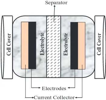
Standard component of EC.—As explained in previous section, a typical of EC unit cell consists of two electrodes immersed in an elec-trolyte and there is one porous separator between the two electrodes. Standard cell of EC is illustrated in Figure3where it is composed
Cell Cover Electrolyte Electrolyte Cell Cover
Current Collector Electrodes
Separator
Figure 3. Common symmetric electrode cell component for EC.
ecsdl.org/site/terms_use address. Redistribution subject to ECS license or copyright; see
of two symmetric electrode materials, separator, electrolyte, and cur-rent collectors. From the figure, curcur-rent collectors are mainly utilizing metal foil or carbon filled polymers and their function is to supply the electrical current to the system. The separator and electrodes are impregnated in the electrolyte, which allows ionic current to flow be-tween the electrodes while preventing electric current from discharg-ing the cell. Moreover, separator between two electrodes also prevents the charge from directly moving between the two electrodes.42 Ac-cording to Ghosh et al., the active material used as electrode, nature of electrolyte and interface between electrodes and electrolytes are the several parameters that influence the performance of ECs.43And, in many laboratory practices, there are several types of cell for ECs are being used such as coin cell, button cell, teflon cell, and button cell.
Usually, in the performance evaluations of the ECs, three-electrode cells are used to test the cell and also to investigate the performance of single electrode. Three electrode cells consist of working elec-trode (materials to be tested), a reference elecelec-trode (to be operational in the electrolyte), and a counter electrode (designed to avoid any interference with the working electrode). When using acidic aque-ous solution, current collectors of working electrode can be titanium, counter electrode is platinum or carbon and reference electrode is sat-urated calomel electrode (SCE) or a silver/silver chloride electrode (Ag/AgCl). Basically the same configuration is used when using neutral aqueous solution but Ni is preferred for the current collec-tor and the counter electrode. In alkaline aqueous solutions, a mer-cury/mercury oxide electrode (Hg/HgO) is used as the reference elec-trode. For non-aqueous electrolyte solutions case by case approach is required depending on the composition of electrolyte.40,41
However, two-electrode cells are recommended for the evaluation of the cell performance. Energy density, power density, and the life cycle of the cell can be easily estimated by using this system. Value of capacitance should be based on the sum of active materials in two electrodes. Also, the capacitance of single electrode measured in a two-electrode cell does not coincide with that in a three-electrode cell because of various factors, such as the difference in sizes between the solvated cation and anion, the different potential changes of positive and negative electrodes during charge/discharge measurements, and others.
The most common techniques for electrochemical testing are CV, galvanostatic potentiometry, rotating disk electrochemistry and impedance spectroscopy. In CV testing, CV curves are rectangular when the capacitance is simply originated from EDLCs. However, when the pseudocapacitance is added, the point of the potential for capacitance calculation should be chosen case by case carefully be-cause the CV curve is not always rectangular.40,41
Electrode fabrication technique based on different carbon materials.—Electrode as the active materials are the main compo-nent of ECs due to capacitance and charge stored depend on the types of electrode material used.8 It is important to fabricate electrodes which are comparable to commercially available ECs because elec-trodes are the active components that will determine the charge storage performance of ECs.45Recently, high surface area and porous carbon materials as well as noble metal oxides are used as electrode material for commercial productions of ECs. However, carbon materials have been widely used as electrode materials for EDLCs.46 High surface area of carbon material such as activated carbon, CNTs, and carbon aerogels are commonly used as electrode materials for EDLCs.47
The energy, power efficiency and lifetime of ECs are also depends on the electrical contact resistance between the electrodes and current collectors.48Electrode surface area, electrode area specific differential capacitance, electrode volumetric capacitance, the frequency behavior of the impedance, the shape of the CV trajectory and the ESR are the basic measures of ECs performance.49The next section will describe about the several types of carbon materials such as CNTs, activated carbons, carbon aerogels, carbon blacks and graphene that have been used to fabricate the high performance of ECs.
Activated carbon.—Activated carbons are especially attractive as electrode material or active ingredient for ECs in order to provide
high capacitance due to high surface area, relatively low cost elec-trode material, and lightweight compared to among different carbon materials.50There are two types of activated carbons; activated car-bon particles/powder and activated carcar-bon fiber cloth. Generally, acti-vated carbons can be obtained from natural sources such as fruit shell like coconut shell, wood, pitch, coke or from synthetic precursors such as selected polymers. Activated carbons will undergo carboniza-tion process and also derived from carbon-rich organic precursors by heat-treatment in inert atmosphere.51 According to Pandolfo et al., activated carbons are also obtained from carbonized phenolic resins or petroleum cokes. Moreover, conductive carbon blacks or graphite are also mixed with activated carbons for utilization in commercial ECs.22
Although the activated carbons able to store less total energy, but they have large percentages of big pores that can deliver high energy at high rate and make them to be more suitable as high power of ECs.52 However, the activated carbons are difficult to handle when in powder form. Thus, conductive agents (carbon black) and polytetrafluoroethy-lene (PTFE) binders are always required.53For EC application, high Cspcan be achieved by choosing a suitable high surface area of ma-terial with BET surface area more than 1,000 m2g−1. For example, EC with Cspof 120 F g−1 is achievable with proper techniques of electrode fabrication.54
Sun et al. investigated electrochemical performance of ECs by us-ing activated carbons as electrode material and Cu (II) containus-ing ionic liquid was used as electrolyte. For the preparation of electrode, acti-vated carbon powders (85 wt%) were mixed with graphite (10 wt%) and polyvinilidene fluoride (PVDF) (5 wt%) as binder material. All the mixtures were stirred adequately, and then pressed to form round electrodes. The round electrode has 10 mm in diameter and 0.2 mm in thickness. The current collector (stainless steel), electrode, separator (polypropylene) and electrolyte solution were assembled in sequence as a sandwich and enveloped in a cell. When Cu (II) containing ionic liquid was used as electrolyte, averageCspdecreased with increasing current intensity, from 225 F g−1at 1 mA cm−2to 210 and 178 F g−1 at 2 and 5 mA cm−2, respectively. Also, high specific energy of about 45 Wh kg−1is attributed to the faradaic pseudocapacitance resulting from the diffusion-controlling, reversible redox reaction of Cu2+/Cu0 ion pairs.55
Kalpana et al. used a poly (o-anisidine-co-metanilic acid) (PASM) /activated carbons as an electrode material for ECs. The PASM were deposited on stainless steel that was coated with activated carbons. For the preparation of activated carbons electrode, 70 wt% of activated carbons with specific surface area of 700 m2 g−1 were mixed with 25 wt% acetylene black and 5 wt% N-methylpyrroli-dine binder. The mixtures were then pressed on a stainless steel grid current collector with geometrical area 1 cm2and kept in an oven at 200◦C for 30 min. Electrochemical testing such as CV and galvanostatic were carried out and the resulted aCspof 373 F g−1at a power density of 0.22 kW kg−1was obtained for PASM/AC at a 5 mV s−1scan rate. However, pulverization may occur during charge and discharge due to thickness and instability of electrodeposited coating. Smaller particle size of PASM may overcome this problem to reduce pulverization and a maximumCspas high as 576 F g−1was obtained.56
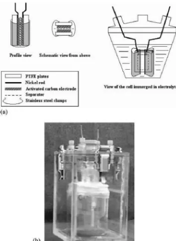
Furthermore, Gamby et al. studied about the several of activated carbon from PICA Company that have been used as electrode materials to compare their performance. Ni foam was used as current collector and 50 µm thick polyethylene sheets were used as separator. The
electrode material was prepared by mixing 95% of activated carbon with 5% of binder (carboxymethylcellulose and PTFE). After drying process, active materials are laminated on each side of the current collector to make 600µm thick electrodes. As shown in Figure4, a
4 cm2test cell with PTFE plates and stainless steel clamp was used to improve the contact inside the cell. Then, the cell is immersed in electrolyte and placed in an argon filled sealed box. The PICACTIF SC carbon was found to be an interesting active material for ECs with aCspas high as 125 F g−1.57As we can see from all previous experiments, activated carbon are always required mixing process with conductive agents and binder material to form slurry and then
ecsdl.org/site/terms_use address. Redistribution subject to ECS license or copyright; see
Figure 4. a) Schematic view of 4 cm2test cell; b) 4 cm2test cell in sealed box.57
coating or pressing on the current collector in order to fabricate the ECs electrode.53
Carbon aerogel and xerogel.—Carbon aerogels have large amounts of mesopores and considered as promising materials for EC. Usually, the size of primary particles carbon aerogels are about 4–9 nm and interconnected with each other to form a network forming interparti-cle mesopores.40According to a method proposed by Pekala, carbon aerogels were derived from pyrolysis of a resorcinol – formaldehyde (RF) gel.58Moreover, sol-gel process with a subsequent drying proce-dure to extract the pore liquid is use to produce aerogels. The particle sizes are controlled by the catalyst concentration and the degree of dilution determines the density of the material.59The advantages of carbon aerogels for EC application are high surface area, great electri-cal conductivity and low density are the several advantages for using in EC application.59,60
Li et al. studied on preparation and performances of carbon aerogel electrodes for the application of ECs. The mass ratio 9:1 of carbon aerogel/graphite was mixed with 5 wt% PTFE (60%) that used as a binder material. All the mixtures were then pressed to form disk like working electrode. Carbon aerogels as electrode materials for ECs were characterized using CV and charge discharge analysis. Result of CV testing indicated a maximumCspof carbon aerogels electrode was 110 F g−1. Meanwhile, a maximumC
spof about 28 F g−1 was obtained through galvanostatic charge discharge testing.46
Liu et al. investigated the performance of resorcinol– formaldehyde-based carbon aerogels in EDLCs. The preparation of carbon aerogels electrodes consist of mixing carbon aerogels, PVDF and carbon black in a weight ratio of 80:10:10. Also, N-methyl-pyrrolidone (NMP) is used to wet the mixture. The mixtures were homogenized in a mortar and finally rolled into a thin film. A 10 mm
ecsdl.org/site/terms_use address. Redistribution subject to ECS license or copyright; see
circular electrode were punched out and pressed onto Ni foam under about 10 MPa for 30 s. Sandwich-type capacitors were prepared with a pair of the carbon aerogel electrodes are separated with a piece of polypropylene membrane as a separator and immersed in 1 M Et4NBF4–AN solution as the electrolyte. From the CV testing, high-estCspof 147 F g−1was exhibited at a scan rate of 5 mV s−1 while the galvanostatic charge discharge testing give the value ofCspabout 152 F g−1.62
As we discuss before this of about common traditional coating process of slurry on the conducting foil to fabricated the EC elec-trode, Hwang and Hyun however developed a cost-effective process for synthesizing resorcinol-formaldehyde (RF) aerogels via ambient drying to make optimal carbon aerogels for EDLCs and electrosorp-tive applications. Carbon aerogel was prepared by pyrolysis of RF aerogels. Pyrolysis of the RF aerogels was carried out under contin-uous nitrogen flow in a tube furnace. It was heated to 300◦C using a heating rate of 2◦C min−1and held there for 2 h. The furnace was then heated up again to 800◦C by heating rates of 3◦C min−1and main-tained for another 1 h. Diamond saw was used to cut carbon aerogel into a disk of 1 mm thickness. After cleaning and drying, the carbon aerogel electrode was activated at 450◦C in hot air environment for 1 h in order to modify surface functionality and improve the affinity with the electrolyte. TheCsphas been improved to 220 Fg−1when carbon aerogel electrodes activated at 450◦
C in air environment for 1 h.63
Carbon black.—Carbon blacks are widely used as conductive fillers for ECs application due to their electrically conductive properties. Usually, carbon blacks are applied for conductivity improvement in polymer engineering and electrochemical industry. It is consisting of composition more or less spherical particles (primary particles) that have diameter in the size range of 10–75 nm to form aggregates (fused primary particles) with size of diameter in 50–400 nm. For EC application, the aggregates form a compact one-, two- or three-dimensional network of the conducting phase when the carbon blacks homogeneously dispersed and mixed with the matrix such as activated carbon, binders, and other additives. Microstructure of carbon blacks are similar like graphite and usually very pure and also considered to be ‘‘amorphous’’.50Generally, the surface areas of carbon blacks are considered to be more accessible than other forms of high surface area carbon. According to Pandolfo et al., EC electrodes have been produced from high surface area blacks (containing a binder) with
Csps of up to 250 F g−1.
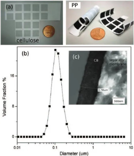
Kossyrev fabricated the electrodes for EC by using traditional coating and inkjet printing on a conventional current collector or directly on a separator membrane. Traditional coating involved casting of carbon black ink containing 2 wt% of solids on top of a 25µm thick
conductive vinyl current collector. The solids in ink constituted of 10 wt% of PTFE binder and 90 wt% of SC3 carbon black which were ultrasonically dispersed in isopropyl alcohol solvent. Also, thin carbon black electrodes are produces directly on separator membranes by inkjet printing. One or both sides of membranes were deposited with carbon black electrodes of around 1µm thickness. For inkjet printing,
2 to 4 wt% of SC3 carbon blacks were ultrasonically dispersed in n-methylpyrrolidone (NMP) solvent and 4 wt% PVDF binders were used. The produced inks were stable over a few days inside the inkjet cartridges. Hence, the utilization of carbon black, SC3 gives aCsp of 115 F g−1 by using an organic electrolyte and a surface area of around 1800 m2 g−1. Examples of supercapacitor electrodes (1 cm
×1 cm), which were inkjet-printed on one side of cellulose separator membrane, and one or both sides of polypropylene (PP) separator membrane is shown in Figure5.64
Nasibi et al. used mechanical pressing as a fast and easy method to fabricate carbon black electrodes. Electrode fabrication tech-nique involves the mixing process of carbon black with PTFE binder (10 wt%) in ethanol to form a paste and then proceed with pressing process onto Ni foil. This work was obtained high specific capacitance of about 33.58 F g−1 C
sp in 2 M KCl elec-trolyte and also the carbon black electrode shows a good cycling performance.65
Figure 5. (a) Examples of supercapacitor electrodes (1 cm×1 cm), which were inkjet-printed on one side of cellulose separator membrane, and one or both sides of polypropylene separator membrane. (b) Particle size distribution of inks containing 4 wt% SC3 carbon black in NMP solvent. (c) TEM image of cross-section of SC3 carbon black electrode (PP) on separator membrane.64
Graphene.—Graphene based ECs are attracting a lot of research atten-tion because they have special structure and excellent performance. Graphene consists of a one atom thick 2D single layer of sp2bonded carbon and it is necessarily to modify or doped graphene to enhance its electrochemical properties. Also, graphene has been considered as the basic construction material for carbon materials in all other dimen-sionalities. On the other hand, graphene has unique properties includ-ing high thermal (∼5,000 W m−1K−1), high electrical conductivity (108S m−1), high transparency (absorbance of 2.3%), great mechani-cal strength (breaking strength of 42 N m−1and Young’s modulus of 1.0 TPa), inherent flexibility, high aspect ratio, and large specific sur-face area (2.63×10⁶m2kg−1).5,64There are four synthesize technique of graphene in the application of ECs which are mechanical exfoli-ation from bulk graphite, arc discharge, chemical vapor deposition (CVD) and epitaxial growth, and reduction of graphite oxides.23,65
Stoller et al. used chemically modified graphene (CMG) to demon-strate an ultracapacitor cell performance. CMG materials are made from 1 atom thick sheets of carbon and it was synthesized by sus-pending graphene oxide sheets in water and then reducing them using hydrazine hydrate. The individual graphene sheets agglomerate into particles approximately 15–25µm diameters during reduction.
Fab-rication of graphene based electrode consisting of mixing process the CMG particles with PTFE binder (3% by weight). The mixtures were then homogenized in an agate mortar, then, rolling the CMG/PTFE mixture into 75µm thick sheets formed into electrodes, and
punch-ing out in 1.6 cm diameter disks. Schematic of test cell and fixture assembly is shown in Figure6, and this ultracapacitor gives the result ofCsps about 135 and 99 F g−1in aqueous and organic electrolytes, respectively.68
Wang et al. used a gas-solid reduction process to prepare the graphene materials and used it as electrode for supercapacitor. The electrodes were fabricated by mixing graphene with 10 wt% PTFE binder. The two graphene electrodes were separated by a thin
ecsdl.org/site/terms_use address. Redistribution subject to ECS license or copyright; see
Figure 6. Schematic of test cell assembly for graphene based electrode.68
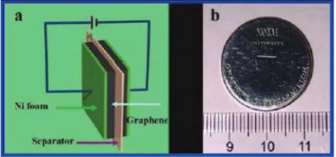
polypropylene film in 30 wt% KOH aqueous electrolyte solutions. The presence of heteroatoms and functional groups in graphene ma-terial is supposed to contribute some pseudocapacitance. However, the linear current with the increase of voltage indicates that there is little faradaic for this supercapacitor. In addition, CV shape shows a rectangular shape with various scan rates and even at a high scan rate of 50 mV s−1. In this work, a maximumC
spof 205 F g−1was obtained with a measured power density of 10 kW kg−1 and energy density of 28.5 Wh kg−1 in an aqueous electrolyte. Schematic diagram of the graphene-based supercapacitor device shown in Figure7depicts the experimental arrangement used to assemble the supercapacitor devices.69
Hsieh et al. fabricated graphene based ECs to see the influence of their physiochemical properties on the performance of the resulting capacitors. Two types of graphene which are graphene nanosheets and graphene oxides electrodes were used as EC electrodes to compare the capacitive performance. They used Hummer’s method to prepare graphene oxide powders while the graphene nanosheet powders were synthesized by chemically reducing the resulting graphene oxides powders. Commercial carbon paper (CP) has been chosen as the sub-strate as an alternative for use as an electrode in the EC. Graphene nanosheets and graphene oxides were sprayed and coated over the CP substrate forming flexible electrodes. The specific discharge capaci-tances of a single electrode in the capacitors were calculated based on the results of charge–discharge cycling. In this work, the discharge ca-pacitances are 158.2 and 17.3 F g−1for graphene oxide and graphene nanosheet capacitors respectively at the discharge current of 5 mA.16 Meanwhile, Yan et al. fabricated high performance of EC elec-trodes based on highly corrugated graphene sheets (HCGS). HCGS have been prepared by a rapid, low cost and scalable approach through
Figure 7. Graphene-based supercapacitor device. (a) Schematic diagram of graphene-based supercapacitor device. (b) An optical image of an industry grade coin-shaped graphene-based supercapacitor device.69
the thermal reduction of graphite oxide at 900◦C followed by rapid cooling using liquid nitrogen. For the fabrication of EC electrode, HCGS were mixed with carbon black and PTFE binder and dispersed in an ethanol. The resulting slurry was then coated onto Ni foam sub-strate. The maximumCspof 349 F g−1at 2 mV s−1is obtained for the HCGS electrode in 6 M KOH aqueous solution. The electrode shows excellent electrochemical stability along with an approximately 8.0% increase of the initial capacitance after 5,000 cycles. These features make the present HCGS material a quite promising alternative for next generation of high-performance supercapacitors.70
On the other hand, Xu et al. also successfully fabricated su-percapacitors using an hierarchical graphene/polypyrrole (GNS/PPy) nanosheet composites as electrode materials by an in situ chemical polymerization method. Sheet-like PPy with a thickness of 20–50 nm was grown on GNS/PPy composites by adjusting the concentration of the pyrrole. The presence of the sheet-like GNS in the synthesis causes the formation of the structure process. The electrode was pre-pared by mixing 5 mg of active materials with 5 mg PVDF. 1 mL of absolute ethanol was then added to the mixtures and sonicated for 1 h to obtain a homogeneous suspension. 10 mL of the homogeneous suspension was dropped onto the glassy carbon electrode and dried in an oven before the electrochemical test. The fabricated supercapacitor was exhibited good electrochemical capacitance as high as 318.6 F g−1at a scan rate of 2 mV s−1.71
Carbon nanotubes.—CNTs were first discovered in 1991 and attracted great interest among scientists around the world. CNT posses out-standing properties such as small dimensions, high strength, and re-markable physical properties that make them as a very unique material with a whole range of promising applications.72The structure of CNT consists of all sp2carbons arranged in graphene sheet which rolled up to form seamless hollow cylinders of graphitic carbon molecules.73 Also, CNTs have excellent stiffness, strength, and thermal conductiv-ity which exceed all other known natural and synthetic materials due to their seamless structure, small diameter and to the resilience of indi-vidual carbon-carbon bonds.74Among others carbon materials, CNTs have been recognized as highly potential electrode carbon materials for EC75because of their remarkable electrical charge storage ability13 high accessible surface area,76low mass density,77excellent electrical conductivity,78great chemical stability79and interconnected network structure.80As compare with activated carbon, CNTs show excellent electrical conductivity, mesoporosity, and electrolyte-accessibility.81 There are two major groups of CNTs which are single walled CNTs (SWCNTs) and multi walled CNTs (MWCNTs).82–84
Technically, CNT based ECs are binder-free and binder-enriched.85 Although the CNTs are mechanically and electrically tight when mixed with polymeric binders, it may contain impurities which can degrade its electrochemical performance.86The binder is required to attach the CNTs to current collectors and tend to increase equiva-lent series resistance (ESR). Also, CNTs are mixed with conductive binder will lead to low contact resistance between CNTs and current collector. This process drastically modifies the properties of CNTs electrode and leading to undesirable performance of the ECs. Cur-rently, many researchers try to develop binder-free for ECs electrode that will enhance the performance of EC in term of charge storage ability and specific capacitance.87 Thus, the electrochemical perfor-mance of CNT based ECs are known to be closely related to many factor such as CNT dispersion/orientation, electrical contact between the electrodes and current collector, and fabrication procedures.
In recent years, ECs based on CNT electrode have been reported using either aqueous or organic electrolytes. In 1996, Niu et al. first introduced the idea to produce double layer capacitor using entangled MWCNT and prepared sheet type CNT electrode by the filtration of a dispersed CNT solution. This technique required no binder and reported a maximumCsp of 113 F g−1 with respect to the unit cell in 38 wt% H2SO4solution. However, the pre-treated with nitric acid increase the parasitic resistance.88Meanwhile, Ma et al. fabricated several types of block-form porous tablets of carbon nanotubes to use as polarizable electrodes in EC. These tablets are prepared by using molded mixtures comprising CNTs and phenolic resin powders
ecsdl.org/site/terms_use address. Redistribution subject to ECS license or copyright; see
capacitors. EC with a specific capacitance of about 15 to 25 F cm−3 are obtained by using these polarizable electrodes.89
There are several reports on the preparation of CNT based EC by mixing with binder material. Frackowiak et al. investigated the elec-trochemical characteristics of an MWCNT pellet electrode prepared by pressing a mixture of CNT with a binder and achieved theCsp ranged from 4 to 135 F g−1in 6 M KOH.90In 2001, An et al. investi-gated the key factors determining the performance of supercapacitors by using SWCNT as the active material. The SWCNTs electrode consisted of 70 wt% of randomly entangled and cross-linked SWC-NTs were mixed with 30 wt% polyvinylidene chloride (PVDC) as the binder material. They achieved result ofCsp of 180 F g−1in 7.5 M KOH.91In same year, Zhang et al. also prepared MWCNT electrodes by molding the CNT with a PTFE binder material and reported aCsp of 18.2 F g−1.92Nowadays, CVD appears as a promising technique for production high quality CNTs at large scales that is achieved by py-rolytic decomposition of hydrocarbon gases at elevated temperatures in the range of 600–1,200◦
C.93There are two major technique used to fabricated CNTs based EC electrodes using CVD process; transfer technique94and direct growth technique.13
(a) CNT: Transfer technique.—Technically, transfer technique is easily defined as transfer of CNTs from non-conducting substrate such as silicon (Si) substrates to the conductive substrate by cut-paste or printing technique to prepare CNT electrode. CNT based ECs are usually made by first growing CNTs on the Si substrate using CVD process when certain reaction parameters such as reaction temperature and the right variety source of gases are carefully selected.94 Unfor-tunately, Si substrate itself cannot be directly utilized as a conductive substrate for CNT electrode because Si is an intrinsic semiconductor. Therefore, transfer technique of CNTs grown from Si substrate to the conducting foils can be utilized in order to prepare CNT electrode. Zhang et al. reported the fabrication of an aligned CNT electrode by a simple cut-paste method, by which the microstructure of the aligned CNT array would not be damaged. They used ferrocene–xylene CVD system to grow 800µm vertically aligned CNTs on a silica substrate.
Then, aligned CNT arrays were removed from the silica substrate with razor blade, and then pasted onto Ni foam current collector to obtain a CNT fur electrode. The CNT fur electrode obtained aCspof 14.1 F g−1at current density 50 mA g−1by using 7 M KOH as electrolyte.95 The same Zhang and co-workers also examined the electrochemi-cal properties of a 500µm aligned CNTs array electrode in an organic
electrolyte by using same cut-paste method and exhibited theCspof 24.5 F g−1. This result showed the improvement value of specific capacitance when using organic electrolyte compare previous work using aqueous electrolyte.96After one year, Zhang et al. fabricated aligned CNT electrode in ionic liquid at 60◦C by using cut-paste method. Aligned CNTs on silica substrate was prepared by CVD as previously reported. For aligned CNT electrode preparation, a 1.0 mm high aligned CNTs were removed from substrate and paste on a Ni foil current collector. TheCspcalculated from the discharge slope mea-sured at 0.05 A g−1was 27 F g−1which is higher than that achieved at aqueous and organic electrolyte.97
Meanwhile, Honda et al. fabricated EDLC by transfer procedure using printing technique a vertically aligned MWCNT sheet from a Si substrate to an aluminum (Al) sheet as a current collector. MWCNTs grown by CVD technique were transferred to Al sheet, and coated homogeneously with a slight amount of electrically conductive ce-ment, phenolic glue containing 5 wt% graphitic carbon thickness to maintain their original vertical alignment even on the Al sheet. From this work, MWCNT sheet electrode provides a discharge capacity of 10–15 F g−1of the aligned MWCNTs even at an extremely high cur-rent density at 200 A g−1. Also, the fabricated EDLC also performed outstanding power density up to 125 kW kg−1 while maintaining a reasonable energy density of 2.2 Wh kg−1.98The same Honda and co-worker also investigated several relationships among the specific capacitances of aligned MWCNT electrodes and their major proper-ties by using same transfer methodology technique like previously work. They found that the rate capability of the aligned MWCNT is
outstanding 300–500 A g−1 irrespective of MWCNTs length. More-over, CV at an extremely high scan rate of 50 V s−1exhibited rapidly responsive charge–discharge currents without a significant distortion for either MWCNT electrode.99Furthermore, Honda et al. success-fully prepared vertically aligned double-walled CNT (DWCNT) sheet by transfer technique from a Si substrate to an Al sheet as a current col-lector for application to a high-performance electrode for an EDLC. The vertically aligned DWCNT was grown using a thermal catalytic CVD technique. It was shown thatCsp of the DWCNT (44 F g−1) electrode was four times larger than that of the MWCNT (10 F g−1) electrode due to decrease in the wall layer number of CNTs enhances the capacitance.100
Lu et al. reported a new class of EC by utilizing transfer technique of vertically aligned CNT and ionic liquids was used as the elec-trolytes. Vertically aligned CNT arrays were grown by vacuum CVD on SiO2(silicon dioxide) / Si wafers. The CNT array was physically removed from the Si wafer using a commercially available double-sided conducting tape. A gold layer was deposited to the (upper) tips of the resultant CNT and used as current collector. Also, plasma etch-ing was used in this work and played an important role in openetch-ing the end tips of CNT. The amorphous carbon layer that covers the CNT film can be properly removed without damaging the CNT. With the underlying gold layer, the resultant plasma-etched aligned CNT elec-trode can be used directly without the incorporation of an insulting polymer binder. The aligned CNT electrode showed butterfly shape of CV. They recorded thatCspof aligned CNT electrode was found to be 440 F g−1(1 V) at 5 mV s−1.25On the other hand, Guittet et al. grew vertically aligned CNT using CVD in Si Substrate and then transfer the CNT onto copper foil tape as current collector in electrochemical cell and multiples parameter of CNT arrays were compared. They found thatCspof the vertically aligned CNT electrodes of about 60 F g−1in 1 M Et4NBF4-PC higher two or three times than that obtained with graphite electrode which is 20 F g−1.101
(b) CNT: Direct growth technique.—Currently, direct growth technique of CNTs onto conducting substrate using catalytic CVD (CCVD) has becoming so effective and useful to fabricate the elec-trode for energy storage devices especially EC. This technique has the advantage of simplifying the electrode assembly and thus reduces the fabrication process. The metal alloy substrate/foil can directly act as a current collector and simplifies the conventional electrode assembly process which is typically associated with active materials composed of conductive and adhesive additive on the current collec-tor. By this technique, binder material and conductive additive which could increase internal resistance and give adverse effect on capaci-tance performance is not incorporated in the device structure. Also, binder materials bring impurities into the electrodes and degrade elec-trochemical performance. Direct growth technique also gives better electrical contact between CNT and current collector.13,102 Consider-ing the connection of the CNT to the current collector, this technique is attractive due to the direct contact between CNT with current col-lector and exhibits one-step process. Current CNT growth methods require purification which results in the degradation of CNT and in-volve higher cost. To overcome this issue, direct growth technique is the best solution to reduce the cost and simultaneously produce high purity CNTs.
Chen et al. directly grew CNT on graphite foil using CVD. Ni catalyst particles were deposited on the graphite foil by magnetron sputtering and then CNT were grown in a pressure of 5–9 Torr main-tained by flowing acetylene and nitrogen gases with a total flow rate of 110 sccm for 1 h at 660◦C. The sample also treated in 15 wt% HNO3aqueous solution for 6 h to ensure that the CNT grew directly on the graphite foil. EDX was employed to examine the position of the Ni catalyst on as-grown and acid-treated. The result showed both before and after acid treatment, the Ni content is higher at the bottom area than at the tip area. CV measurement was done and the result of rectangular-shaped CV suggests that the CNT electrode is an excellent candidate for EDLC. The averageCspcan be obtained by integrating oxidation currents in the CV curve. The results ofCsp are as high
ecsdl.org/site/terms_use address. Redistribution subject to ECS license or copyright; see
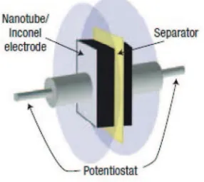
Figure 8. The experimental arrangement used to fabricate and measure the EDLC properties of the CNT–Inconel electrodes.102
as 115.7 F g−1 and 146.6 F g−1 at potential scan rates of 100 and 25 mV s−1, respectively.85Talapatra et al. reported the direct growth of aligned CNT on a metallic alloy (Inconel 600) using vapor-phase catalyst delivery. They was used a ferrocene–xylene CVD system for the growth of vertically aligned CNT and obtained the value ofCspfor EC calculated from the discharge slope at 2 mA was found to be 18 F g−1The experimental arrangement used to fabricate and measure the EC properties of the CNT-Inconel electrode is shown in Figure8.103
Furthermore, Gao et al.grew aligned CNT arrays with lengths up to 150µm on Inconel 600 by pyrolysis of iron (II) phthalocyanine
(FePc) in the presence of ethylene. TheCsps recorded at 1 mVs−1and 1,000 mVs−1 were 83 F g−1 and 47 F g−1, respectively.102 This in-dicates that the aligned CNT electrode for supercapacitor application has an excellent rate capability. On the other hand, Zhang et al. inves-tigated electrochemical capacitive properties of CNT arrays directly grown on glassy carbon and tantalum (Ta) foils to fabricate superca-pacitor electrodes. The CV curve showed rectangular shaped andCsp obtained at 0.5 A g−1of the CNT on glassy carbon and Ta are 27 and 28 F g−1, respectively. Also, no obvious degradation was observed after the CNT electrodes were cycled for 10,000 times.104 Shah et al. reported on the fabrication of EDLC electrodes with aligned CNT directly grew on Inconel using an air assisted CVD technique. The CV was rectangular in shape within a selected range of potential, sug-gesting that the integrated CNT-current collector systems have very rapid current response on voltage reversal with low ESR. TheCspof the CNT used for EDLC electrodes increased with decreasing CNT lengths and ranged from 10.75 F g−1to 21.57 F g−1.19
Kavian et al. reported direct growth of MWCNT by using CVD on pure aluminum (Al) foils for preparation of supercapacitor electrode. CV analysis was performed on the CNT electrodes in an organic electrolyte and 1 M H2SO4 electrolyte at scan rate of 100, 50, and 20 mV s−1resulting a high value of theC
spabout 54 F g−1in aqueous electrolyte and 79 F g−1in organic electrolyte.105Meanwhile, Kim et al. demonstrated vertically aligned CNT directly grew on Ta substrate via water assisted CVD and evaluated CNT properties for electro-chemical capacitor applications. For electroelectro-chemical measurement, almost ideal rectangular CV shape was observed at the scan rate of
∼1 V s−1, and specific capacitance was retained (94% retention) even at a high discharge current density of 145 A g−1. Also, power density andCspestimated from CV curve are about 60 kW kg−1 and 13 F g−1 respectively.87At same year, Kim et al. grew vertically aligned CNT on stainless steel by water assisted CVD. Electrical measurement confirmed that the CNT were electrically connected to the stainless steel.106Kim et al. also fabricated high performance supercapacitor based on vertically aligned CNT and non aqueous electrolyte such as ionic liquid and conventional organic electrolyte. CNT were grown directly on carbon paper via CVD method. CV analysis showed the CNT based supercapacitor had excellent capacitive properties. Ac-cording to Kim’s work,Csp, power density, and energy density of the supercapacitor measured in ionic liquid were 75 F g−1, 987 kW kg−1, and 27 Wh kg−1, respectively. Both high power and energy density
could be attributed to the fast ion transport realized by the alignment on CNT and the wide operational voltage defined by the ionic liquid. Also, electrochemical oxidations of the CNTs have been improved theCspand energy density of about 158 F g−1and 53 Wh kg−1. This could be attributed to the fast ion transport through aligned structure of CNTs.107
Meanwhile, Azam et al. investigated direct growth of vertically-aligned SWCNT on conducting substrates using ethanol CVD to fab-ricate EC. Direct growth technique using alcohol CCVD (ACCVD) was employed to fabricate vertically aligned SWCNT electrode onto conducting SUS 310S foil in which binder material was not incorpo-rated in the structure of EC.108Electrochemical analysis using KOH electrolyte was performed by using CV and galvanostatic charge-discharge measurements and obtained a maximum 52 F g−1Csp. Also, Azam et al. fabricated an EC that achieved very highCsp of up to 584 F g−1(at 1 mV s−1) using ionic liquid as electrolyte.13 During ACCVD, the lack of amorphous carbon was attributed to the OH− radical present in ethanol, which preferentially reacts with carbon molecules that have dangling bonds effectively etches away those carbon atoms that are most likely to produce amorphous carbon. Di-rect growth of SWCNT on pure metal, however, results in inevitable degradation of the foils, such as melting at the CVD growth tem-perature, thus, metal alloy foils are suitable use as conducting foil because of their durability under CVD conditions, and their corrosion resistivity, especially during high-applied potential electrochemical measurements.109
Important point of the review.—Carbon material being used as elec-trode, the fabrication technique, types of cell assembly, and findings of the performance of ECs are summarized in TableI. Figure9shows the process flow diagram for various electrode fabrication techniques. Most of the fabrication techniques undergone deposition or coating on conducting foil from slurry obtained by mixing the carbon materials with a binder and conductive materials. From one point of this review, Kalpana and co-workers were successfully obtained highCspof about 573 F g−1 using activated carbon as electrode material.56 However, this technique leads to pulverization during charge discharge due to thickness and instability during coating process. Hence, small par-ticles size of PASM may overcome this problem and achieved high specific capacitance.
Significant achievement of theCspwas obtained through CNT di-rect growth technique. Azam et al. was successfully obtained highest
Cspof about 584 F g−1by using direct growth of CNT onto conduct-ing foil.13The capacitance performance achieved by Azam’s work is almost similar to that of Kalpana work, but the fabrication technique simplifies the conventional electrode assembly by avoiding binder, reduces the process steps, which in theoretical can attribute to the optimum charge storage performance.
Application of EC (Current Market Availability, Potential Application, Future Prospective)
This section discusses several applications that uses EC as energy storage which reveal how charge/discharge time and cycle life dif-ferences affect the applicability of the technologies. EC are energy storage device with high power delivery and uptake and with an ex-ceptional cycle life. They are used when high power demands are needed, such as for power buffer and power saving units and also of great interest for energy recovery. EC are many used in automotive engineering, railway traction, telecommunication systems, industrial, medical and consumer electronics.1
Currently, EC also used for energy management and conservation applications such as in seaport crane. One important function of EC in this application is to capture energy that would otherwise be wasted as heat in the repetitious up and down movement of heavy shipping containers. Also, EC allow a size reduction in the primary power source usually a diesel engine. EC are also applicable for hybrid electric vehicles such as metro trains and tramways. In this application, EC will allow store the energy obtained from regenerative braking and
ecsdl.org/site/terms_use address. Redistribution subject to ECS license or copyright; see
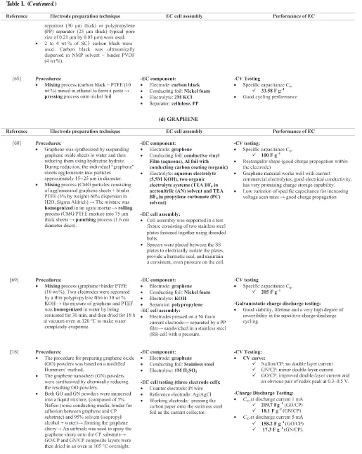
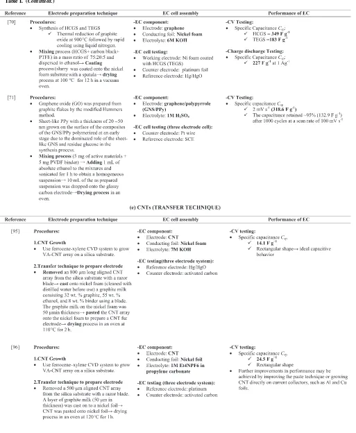
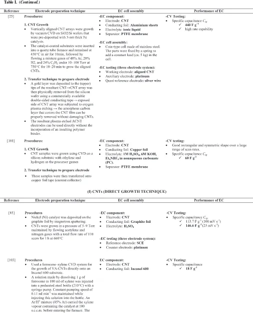
Table I. Summary of carbon material based electrodes, the fabrication techniques, types of cell, and the electrochemical performances.
ecsdl.org/site/terms_use address. Redistribution subject to ECS license or copyright; see
Table I. (Continued.)
ecsdl.org/site/terms_use address. Redistribution subject to ECS license or copyright; see
Table I. (Continued.)
ecsdl.org/site/terms_use address. Redistribution subject to ECS license or copyright; see
Table I. (Continued.)
ecsdl.org/site/terms_use address. Redistribution subject to ECS license or copyright; see
Table I. (Continued.)
ecsdl.org/site/terms_use address. Redistribution subject to ECS license or copyright; see
Table I. (Continued.)
ecsdl.org/site/terms_use address. Redistribution subject to ECS license or copyright; see
Table I. (Continued.)
ecsdl.org/site/terms_use address. Redistribution subject to ECS license or copyright; see
Table I. (Continued.)
ecsdl.org/site/terms_use address. Redistribution subject to ECS license or copyright; see
Table I. (Continued.)
Conventional Coating/Deposition Process Transfer technique Direct growth technique
Conducting foil Catalyst support
Conducting foil Active material
+
Mixing process to form slurry
Conductive material +
Binder material
Coating process onto conducting foil
Slurry (active material +
Conductive material +
Binder material)
Conducting foil
Carbon growth onto silicon wafer using
CVD process
Silicon wafer Catalyst support Catalyst
CNT + Catalyst particles
Silicon wafer
Transfer process onto conducting foil
CNT + Catalyst particles
Silicon wafer
Cutting process
CNT + Catalyst particles
Conducting foil
Paste process
Catalyst
CNT + Catalyst particles Direct growth of CNT onto conducting
foil using CVD
Razor blade
Figure 9. Schematic of process flow diagram for various electrode fabrication techniques.
this energy will be reused in the next acceleration phase and allow fast acceleration. For automotive applications, manufacturers are already proposing solutions for electrical power steering, where EC are used for load-leveling in stop-and-go traffic.110
The largest part of the EC sold nowadays are used in consumer electronic products, where they mainly serve as backup sources for memories, microcomputers, system boards, and clocks. In these ap-plications there is a primary power source which normally supplies the load. In case of power outages due to disconnection or turn-off of the primary source, contact problems due to vibration or shocks, or a drop of the system voltage due to switching in of other heavy loads, the EC can supply the critical consumers. Hence, EC has the
strong capability to be used in many applications and technologies as key role in energy storage and harvesting, decreasing the total energy consumption and minimizing the use of hydrocarbon fuels.7
Summary
To conclude, there are various electrode fabrication techniques based on different types of carbon materials available for the devel-opment of electrochemical capacitors (ECs). However, it is important to note that the selection of materials and processing techniques to fabricate the EC will determine the performance of EC as energy
ecsdl.org/site/terms_use address. Redistribution subject to ECS license or copyright; see
storage device. Carbon materials have been focused as a highly po-tential electrode material for EC due to their remarkable electrical charge storage ability. In this article, it was found that conventional technique; mixing the commercially available carbon material with conductive agent and binder material during the slurry preparation process is mostly selected. The binder materials used in the slurry could increase the internal resistance of EC and thus may nega-tively affect the electrochemical performance. Another approach of preparing the electrode is to synthesize carbon nanomaterial on Si wafer, and then the materials are transferred to conducting substrate by cutting and pasting (or printing) them onto conducting current col-lector, but again with the help of adhesive. To overcome this issue, direct growth technique of CNTs onto conducting foil has become an effective technique to simplify the electrode fabrication process, and importantly without the incorporation of binder and/or adhesive material. There are still many approaches from researchers trying to develop electrode fabrication technique that might enhance the EC performance from different aspects. Future research and development efforts to solve these matters are highly expected.
Acknowledgment
This work was financially supported by the Ministry of Higher Education (MOHE), Malaysia, and eScienceFund research grant from Ministry of Science, Technology and Innovation (MOSTI), Malaysia No.: 03-01-14-SF006.
References
1. P. Simon and Y. Gogotsi,Nat. Mater.,7, 845 (2008).
2. T. Nguyen and R. F. Savinell,Electrochem. Soc. Interface,19, 54 (2010). 3. X. Li and B. Wei,Nano Energy,2, 159 (2013).
4. H. D. Abru˜na, Y. Kiya, and J. C. Henderson,Phys. Today.,61, 43 (2008). 5. Y. Huang, J. Liang, and Y. Chen,Small,8, 1805 (2012).
6. M. Winter and R. J. Brodd,Chem. Rev.,104, 4245 (2004). 7. R. Kotz and M. Carlen,Electrochim. Acta,45, 2483 (2000). 8. H. Pan, J. Li, and Y. P. Feng,Nanoscale Res. Lett.,5, 654 (2010). 9. Y. Show,Journal of Nanomater.,2012, 1 (2012).
10. A. Burke,J. Power Sources,91, 37 (2000).
11. I. Hadjipaschalis, A. Poullikkas, and V. Efthimiou,Renew. Sust. Energ. Rev.,13, 1513 (2009).
12. M. V. Kiamahalleh, S. H. S. Zein, G. Najafpour, S. A. Sata, and S. Buniran,Nano,
7, 1230002 (2012).
13. M. A. Azam, K. Isomura, A. Fujiwara, and T. Shimoda,Phys. Status Solidi A,209, 2260 (2012).
14. A. Izadi-Najafabadi, S. Yasuda, K. Kobashi, T. Yamada, D. N. Futaba, H. Hatori, M. Yumura, S. Iijima, and K. Hata,Adv. Mater.,22, E235 (2010).
15. C. Emmenegger, P. Mauron, P. Sudan, P. Wenger, V. Hermann, R. Gallay, and A. Z¨uttel,J. Power Sources,124, 321 (2003).
16. C.-T. Hsieh, S.-M. Hsu, and J.-Y. Lin,Jpn. J. Appl. Phys.,51, 01AH06 (2012). 17. J. M. Boyea, R. E. Camacho, S. P. Turano, and W. J. Ready,Nanotechnology Law
& Business,4, 585 (2007).
18. V. V. N. Obreja,Physica E,40, 2596 (2008).
19. R. Shah, X. Zhang, and S. Talapatra,Nanotechnology,20, 395202 (2009). 20. J. Shen, A. Liu, Y. Tu, G. Foo, C. Yeo, M. B. Chan-Park, R. Jiang, and Y. Chen,
Energy Environ. Sci.,4, 4220 (2011).
21. X. He, L. Jiang, S. Yan, J. Lei, M. Zheng, and H. Shui,Diam. Relat. Mater.,17, 993 (2008).
22. A. G. Pandolfo and A. F. Hollenkamp,J. Power Sources,157, 11 (2006). 23. J. Li, X. Cheng, A. Shashurin, and M. Keidar,Graphene,1, 1–13 (2012). 24. R. N. Reddy and R. G. Reddy,J. New Mater. Electrochem. Syst.7, 317 (2004). 25. W. Lu, L. Qu, K. Henry, and L. Dai,J. Power Sources,189, 1270 (2009). 26. J. R. Miller and P. Simon,Electrochem. Soc. Interface,17, 31 (2008). 27. G. Gourdin, T. Jiang, P. Smith, and D. Qu,J. Power Sources,215, 179 (2012). 28. E. Frackowiak,Phys. Chem. Chem. Phys.,9, 1774 (2007).
29. J. R. Miller and P. Simon,Science,321, 651 (2008).
30. P. Simon and Y. Gogotsi,Phil. Trans. R. Soc.,368, 3457 (2010).
31. A. K. Shukla, S. Sampath, and K. Vijayamohanan,Curr. Sci.,79, 1656 (2000). 32. O. Barbieri, M. Hahn, A. Herzog, and R. K¨otz,Carbon,43, 1303 (2005). 33. Y. Korenblit, M. Rose, E. Kockrick, L. Borchardt, A. Kvit, S. Kaskel, and G. Yushin,
ACS Nano,4, 1337 (2010).
34. F. V. Mulders, J. Timmermans, Z. Mccaffrey, J. V. Mierlo, and P. V. D. Bossche,
WEV Journal,2, 32 (2008). 38. A. Balducci, R. Dugas, P. L. Taberna, P. Simon, D. Pl´ee, M. Mastragostino, and
S. Passerini,J. Power Sources,165, 922 (2007).
39. M. K. Ravikumar, E. Niranjana, A. S. Rajan, A. Banerjee, S. A. Gaffoor, and A. K. Shukla,J. Indian Inst. Sci.89, 455 (2009).
40. M. Inagaki, H. Konno, and O. Tanaike,J. Power Sources,195, 7880 (2010). 41. F. Lufrano and P. Staiti,Int. J. Electrochem. Sci.,5, 903 (2010).
42. M. D. Stoller and R. S. Ruoff,Energy Environ. Sci.,3, 1294 (2010). 43. A. Ghosh and Y. H. Lee,ChemSusChem.,5, 480 (2012).
44. F. B´eguin and E. Frackowiak,CRC Press, p. 11, Taylor & Francis Group, USA (2010).
45. K. Jost, C. R. Perez, J. K. McDonough, V. Presser, M. Heon, G. Dion, and Y. Gogotsi, Energy Environ. Sci.,4, 5060 (2011).
46. J. Li, X. Wang, Q. Huang, S. Gamboa, and P. J. Sebastian,J. Power Sources,158, 784 (2006).
47. M. N. Patel, X. Wang, D. A. Slanac, D. A. Ferrer, S. Dai, K. P. Johnston, and K. J. Stevenson,J. Mater. Chem.,22, 3160 (2012).
48. Z. Zhou and X.-F. Wu,J. Power Sources,222, 410 (2013).
49. R. Signorelli, D. C. Ku, J. G. Kassakian, and J. E. Schindall,Proceedings of the IEEE,97, 1837 (2009).
50. M. Zhu, C. J. Weber, Y. Yang, M. Konuma, U. Starke, K. Kern, and a. M. Bittner, Carbon,46, 1829 (2008).
51. P. Simon and A. Burke,Electrochem. Soc. Interface,17, 38 (2008). 52. E. Frackowiak and F. B´eguin,Carbon,39, 937 (2001).
53. G. Xu, C. Zheng, Q. Zhang, J. Huang, M. Zhao, J. Nie, X. Wang, and F. Wei,Nano Res.,4, 870 (2011).
54. D. Qu and H. Shi,J. Power Sources,74, 99 (1998).
55. G. Sun, K. Li, and C. Sun,Microporous Mesoporous Mater.,128, 56 (2010). 56. D. Kalpana, Y. S. Lee, and Y. Sato,J. Power Sources,190, 592 (2009). 57. J. Gamby, P. L. Taberna, P. Simon, J. F. Fauvarque, and M. Chesneau,J. Power
Sources,101, 109 (2001).
58. B. Fang and L. Binder,J. Power Sources,163, 616 (2006).
59. R. Saliger, U. Fischer, C. Herta, and J. Fricke,J. Non-Cryst. Solids,225, 81 (1998). 60. R. W. Pekala, J. C. Farmer, C. T. Alviso, T. D. Tran, S. T. Mayer, J. M. Miller, and
B. Dunn,J. Non-Cryst. Solids,225, 74 (1998).
61. H. Probstle, C. Schmitt, and J. Fricke,J. Power Sources,105, 189 (2002). 62. N. Liu, J. Shen, and D. Liu,Microporous Mesoporous Mater.,167, 176 (2013). 63. S.-W. Hwang and S.-H. Hyun,J. Non-Cryst. Solids,347, 238 (2004). 64. P. Kossyrev,J. Power Sources,201, 347 (2012).
65. M. Nasibi, G. Rashed, and M. A. Golozar,ICMMAE(2012). 66. J. Liu, Y. Xue, M. Zhang, and L. Dai,MRS Bulletin,37, 1265 (2012).
74. M. A. Azam, K. Isomura, A. Fujiwara, and T. Shimoda,Global Engineers & Tech-nologists Review,1, 1 (2011).
75. M. A. Azam, M. W. A. Rashid, K. Isomura, A. Fujiwara, and T. Shimoda,Adv. Mat. Res.,620, 213 (2012).
76. M. Guittet, A. I. Aria, and M. Gharib,11th IEEE International Conference on Nanotechnology, 80 (2011).
77. C. Du and N. Pan,Nanotechnology,17(21), 5314 (2006).
78. D. N. Futaba, K. Hata, T. Yamada, T. Hiraoka, Y. Hayamizu, Y. Kakudate, O. Tanaike, H. Hatori, M. Yumura, and S. Iijima,Nat. Mater.,5, 987 (2006). 79. C. Du, J. Yeh, and N. Pan,Nanotechnology,16, 350 (2005).
80. R. Shi,Soft Nanoscience Letters,1, 11 (2011).
81. W. Lu, R. Hartman, L. Qu, and L. Dai,J. Phys. Chem. Lett.,2, 655 (2011). 82. J. Seetharamappa, S. Yellappa, and F. D’Souza,Electrochem. Soc. Interface(2006). 83. W. S. Su, T. Leung, and C. T. Chan,Phys. Rev. B,76, 235413 (2007).
84. Q. Cheng, J. Ma, H. Zhang, N. Shinya, L. Qin, and J. Tang,Transactions of the Materials Research Society of Japan,35, 369 (2010).
85. J. H. Chen, W. Z. Li, D. Z. Wang, S. X. Yang, J. G. Wen, and Z. F. Ren,Carbon,
90. E. Frackowiak, K. Metenenier, V. Bertangna, and F. Beguin,Appl. Phys. Lett.,77, 2421 (2000).
93. M. Kumar and Y. Ando,J. Nanosci. Nanotechno.,10, 3739 (2010). 94. L. Basiric`o and G. Lanzara,Nanotechnology,23, 305401 (2012). 95. H. Zhang, G. P. Cao, and Y. S. Yang,Nanotechnology,18, 195607 (2007). 96. H. Zhang, G. Cao, and Y. Yang,J. Power Sources,172, 476 (2007).
ecsdl.org/site/terms_use address. Redistribution subject to ECS license or copyright; see
97. H. Zhang, G. Cao, Y. Yang, and Z. Gu,Carbon,46, 30 (2008).
98. Y. Honda, T. Haramoto, M. Takeshige, H. Shiozaki, T. Kitamura, and M. Ishikawa, Electrochem. Solid. St.,10, A106 (2007).
99. Y. Honda, T. Haramoto, M. Takeshige, H. Shiozaki, T. Kitamura, K. Yoshikawa, and M. Ishikawa,J. Electrochem. Soc.,155, A930 (2008).
100. Y. Honda, M. Takeshige, H. Shiozaki, T. Kitamura, K. Yoshikawa, S. Chakrabarti, O. Suekane, L. Pan, Y. Nakayama, M. Yamagata, and M. Ishikawa,J. Power Sources,
185, 1580 (2008).
101. M. Guittet, A. I. Aria, and M. Gharib,11th IEEE International Conference on Nanotechnology, 80 (2011).
102. L. Gao, A. Peng, Z. Y. Wang, H. Zhang, Z. Shi, Z. Gu, G. Cao, and B. Ding,Solid State Commun.,146, 380 (2008).
103. S. Talapatra, S. Kar, S. K. Pal, R. Vajtai, L. Ci, P. Victor, M. M. Shaijumon, S. Kaur, O. Nalamasu, and P. M. Ajayan,Nat. Nanotechnol.,1, 112 (2006).
104. H. Zhang, G. Cao, Z. Wang, Y. Yang, and Z. Gu, Carbon, 46, 822 (2008).
105. R. Kavian, A. Vicenzo, and M. Bestetti,J. Mater. Sci.,46, 1487 (2010). 106. B. Kim, H. Chung, K. S. Chu, H. G. Yoon, C. J. Lee, and W. Kim,Synthetic Met.,
160, 584 (2010).
107. B. Kim, H. Chung, and W. Kim,Nanotechnology,23, 155401 (2012).
108. M. A. Azam, A. Fujiwara, and T. Shimoda,J. New. Mat. Electr. Sys.,178, 173 (2011).
109. M. A. Azam, N. S. A. Manaf, E. Talib, and M. S. A. Bistamam,Ionics(2013). 110. J. R. Miller and A. F. Burke,Electrochem. Soc. Interface,17, 53 (2008).
ecsdl.org/site/terms_use address. Redistribution subject to ECS license or copyright; see