RFID SMART KEY DETECTOR
AL-AWAZANGI BIN SHA‟ARANI
This report is submitted in partial fulfilment of the requirements for the award of Bachelor of Electronic Engineering (Industrial Electronics) With Honours
Faculty of Electronic and Computer Engineering Universiti Teknikal Malaysia Melaka
UNIVERSTI TEKNIKAL MALAYSIA MELAKA
FAKULTI KEJURUTERAAN ELEKTRONIK DAN KEJURUTERAAN KOMPUTER
BORANG PENGESAHAN STATUS LAPORAN
mengaku membenarkan Laporan Projek Sarjana Muda ini disimpan di Perpustakaan dengan syarat-syarat kegunaan seperti berikut:
1. Laporan adalah hakmilik Universiti Teknikal Malaysia Melaka.
2. Perpustakaan dibenarkan membuat salinan untuk tujuan pengajian sahaja.
3. Perpustakaan dibenarkan membuat salinan laporan ini sebagai bahan pertukaran antara institusi pengajian tinggi.
4. Sila tandakan ( √ ) :
SULIT*
(Mengandungi maklumat yang berdarjah keselamatan atau kepentingan Malaysia seperti yang termaktub di dalam AKTA RAHSIA RASMI 1972)
TERHAD* (Mengandungi maklumat terhad yang telah ditentukan oleh
organisasi/badan di mana penyelidikan dijalankan)
TIDAK TERHAD
Disahkan oleh:
__________________________ ___________________________________ (TANDATANGAN PENULIS) (COP DAN TANDATANGAN PENYELIA)
iii
“I hereby declare that this report is the result of my own work except for quotes as cited in the references.”
Signature : ………
Name : AL-AWAZANGI BIN SHA‟ARANI
iv
“I hereby declare that I have read this report and in my opinion this report is sufficient in terms of the scope and quality for the award of Bachelor of Electronic
Engineering (Industrial Electronics) With Honours.”
Signature : ………..
Supervisor‟s Name : EN. ZULKARNAIN BIN ZAINUDIN
v
Special dedicated to
my beloved parents and siblings, who encouraged, guided and supported me
vi
ACKNOWLEDGEMENT
Thanks to Allah S.W.T., with His Compassion and Grace, I can manage to complete the project with a group of knowledgeable people while doing my project a pleasant and exciting experiences one. Their help and support throughout is greatly appreciated. I would like to give the highest gratitude to my supervisor, Mr. Zulkarnain Bin Zainudin, for his help, advices and responsibilities throughout the project especially during difficult time. Not to forget, thanks to my beloved parents for their encouragement and moral support.
vii
ABSTRACT
viii
ABSTRAK
ix
1.1 Background of Project 1
1.2 Objectives of Project 3
1.3 Problems Statement 3
1.4 Scopes of Project 3
1.5 Brief Methodology 4
x
II LITERATURE VIEW 6
2.1 Literature Review Overview 6
2.2 Proximity Security System for Cornell
University ID 6
2.3 RFID-Based Anti-theft Auto Security System
With an Immobilizer 8
2.3.1 Basic Operation 8
2.3.1.1 Transmitting Unit 9
2.3.1.2 Receiving Unit 10
2.4 Automatic Vehicle Access 11
2.5 Theory on Devices 12
2.5.1 Software Design 12
2.5.1.1 C Language 12
2.5.1.2 Assembly Language 14 2.5.2 Microchip PIC16F876A Microcontroller 15 2.5.3 LCD Alphanumeric Display 17 2.5.4 Voltage Regulator (LM7805) 18
2.5.5 RFID Reader IDR-232 19
3.3.1.4 Create the Project 25
3.3.1.5 Add Files 27
3.3.1.6 Create the Programming Code
xi
3.4 PIC 16F876A Microcontroller 29
3.4.1 I/O Ports 29
3.4.2 PORTA and TRISA Register 29 3.4.3 PORTB and TRISB Register 30
3.4.5 PORTC and TRISC Register 30
3.5 Programming the LCD Display 30
3.6 Setup RFID Reader IDR-232 32
3.6.1 Pin Configuration 35
3.7 Voltage Regulator Circuit 36
3.8 Interface PIC16F876A with Buzzer 37 3.9 Interface PIC16F876A with Relay 38 3.10 ICSP for Programming PIC Microcontroller 38 3.11 Push Button as Input for PIC Microcontroller 39 3.12 LED as Output for PIC Microcontroller 39
3.13 Reset circuit 40
3.14 PCB designation 41
IV RESULTS AND DISCUSSION 43
4.1 Results Overview 43
4.2 Expected Results 43
4.3 Flowchart of Programming 44
4.4 Testing PIC 16F876A 45
4.5 Circuit Description 45
4.6 Problems 47
4.6.1 LCD Display 47
4.6.2 Others 49
xii
V CONCLUSION AND RECOMMENDATION 51
5.1 Conclusion 51
5.2 Recommendation 52
xiii
LIST OF TABLES
NO TITLE PAGE
2.1 List of Voltage Regulators 18
3.1 LCD Connection and Function of Each Pin 31
xiv
LIST OF FIGURES
NO TITLE PAGE
1.1 Basic System Operation 4
2.1 RFID Reader with Combination of Door Lock 7
2.2 ID Cards Posing with the RFID Reader 7
2.3 Transmitting Unit Functional Block Diagram 9 2.4 Receiving Unit Functional Block Diagram 10
2.5 Automatic Vehicle Access 11
2.6 Pin Diagram of PIC 16F876A 16
2.7 Physical of LCD Display 17
2.8 Voltage Regulator 18
2.9 RFID Reader IDR-232 19
3.1 Flowchart of the Project Methodology 21
3.2 Circuit for RFID Smart Key Detector 22
3.3 Devices Selection 24
3.4 Selecting Toolsuite 25
3.5 Create Project File 26
3.6 Summary of Project Wizard 26
3.7 Adding the Programming Code 27
3.8 Create the Programming Code (*.Hex) 28
3.9 Debug the Programming Code 28
3.10 Programming Code in *.Hex File 29
3.11 Characteristic in LCD Display 31
3.12 5V dc Supply Voltage for IDR-232 32
3.13 Communication Line Connected to Serial Port of PC 33
xv
3.15 Tag‟s ID Shows in HyperTerminal 34
3.16 5 Wires of RFID Reader 35
3.17 Connection of IDR-232 in Circuit 36
3.18 Voltage Regulator Circuit 37
3.19 Buzzer Connection in Circuit 37
3.20 UIC00A Connection in Circuit 38
3.21 Push Button as Input 39
3.22 LED Pin Connection as Output 40
3.23 The Photolithography Process Sequence 41 3.24 PCB Layout for RFID Smart Key Detector using Proteus 7 42
4.1 Flowchart of Programming 44
4.2 Circuit Running in Proteus 7.1 46
4.3 RFID Smart Key Detector Prototype 47
4.4 Error Language Display on LCD 48
4.5 LCD Displayed as Required 48
xvi
LIST OF ABBREVIATION
RFID - Radio Frequency Identification EPC - Electronic Product Code
ICAO - International Civil Aviation Organization LED - Light Emitting Diode
FSK - Frequency Shift Keying
AM - Amplitude Modulation
GPS - Global Positioning System
RF - Radio Frequency
PIC - Peripheral Interface Controller CPU - Central Processing Unit
I/O - Input / Output
EEPROM - Electrically Erasable Programmable Read-Only Memory SRAM - Static Random Access Memory
CMOS - Complementary Metal Oxide Semiconductor LCD - Liquid Crystal Display
RAM - Random Access Memory
PC - Personal Computer
xvii
LIST OF APPENDICES
NO TITLE PAGE
A Programming Code in C Language 54
B Datasheet PIC 16F876A 60
CHAPTER I cluttered breakfast in the morning for example. RFID may be viewed as a means of explicitly labelling objects to facilitate their perception by computing devices. An RFID tag is a small microchip designed for wireless data transmission. It is generally attached to an antenna in a package that resembles an ordinary adhesive sticker. The microchip itself can be as small such 0.4mm2. An RFID tag transmits data over the air in response to interrogation of reader.
2
Today, RFID is seeing fruition in the tagging of crates and pallets, that is, discrete bulk quantities of items. RFID tagging improves the accuracy and timeliness of information about the movement of goods in supply chains. The main form of barcode type RFID device is known as an EPC. An organization known as EPCglobal Inc. oversees the development of the standards for these tags.
In general, small and inexpensive RFID tags are passive, there is no on-board power source and they derive their transmission power from the signal of an interrogating reader. This will be discuss lately in chapter 3; methodology.
Many of us already use RFID tags routinely. Examples include proximity cards, automated toll-payment transponders, and payments tokens. The ignition keys of many millions of automobiles moreover include RFID tags as a theft-deterrent. RFID privacy is already concern in several areas of everyday life:
Libraries – Some libraries have implemented RFID systems to facilitate book checkout and inventory control and reduce repetitive stress injuries in librarians
Passports – An international organization known as ICAO has promulgated guidelines for RFID-enabled passports and other travel documents
Human Implantation – Few other RFID systems have inflamed the passions of privacy advocates like the VeriChip system. VeriChip is a human-implantable RFID tag, much like the variety for the house pets
3
1.2 Objectives of Project
The aims of doing this project are stated below:
Build up security system base on the RFID application
To learn how to integrate RFID circuit with ignition coil of motorcycle
To avoid and reduce duplication key
1.3 Problems Statement
In this project, the scope is based on two major parts. By understanding these elements, the maximum usage of RFID can be obtained to fulfil the requirement.
Research and find information about RFID
4
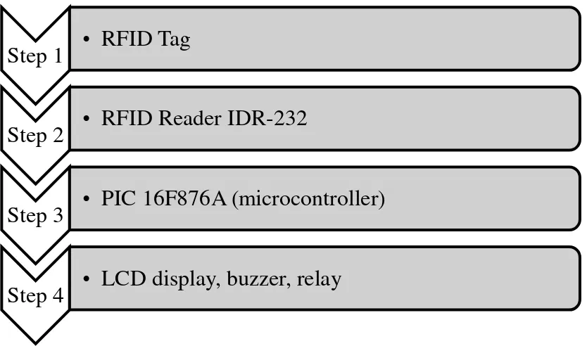
1.5 Brief Methodology
In order to complete this project, there are so many works that need to be done. The first stage is by understanding the concept of RFID. The second stage will be more on choosing the best RFID reader and passive tag in market and combination of ignition coil of motorcycle. The third stage is about test the hardware and makes troubleshoot the hardware problems if occurred.
Figure 1.1: Basic System Operation
Step 1
•
RFID Tag
Step 2
•
RFID Reader IDR-232
Step 3
•
PIC 16F876A (microcontroller)
5
1.6 Outline of Thesis
HAPTER II
LITERATURE REVIEW
2.1 Literature Review Overview
This chapter discuss about reviews of existing project created to get an idea about the project design, conception and any information that related to improve the project. With different concept and design, there are other creation and innovation of project done by other people.
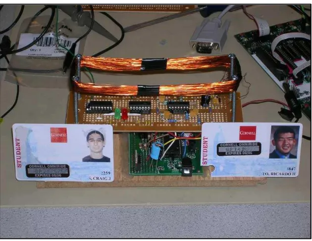
2.2 Proximity Security System for Cornell University ID
7
Figure 2.1: RFID Reader with Combination of Door Lock