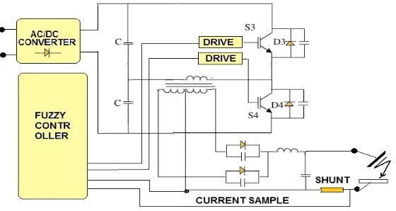
Operation of a Fuzzy Controlled Half-Bridge DC-Converter as a Welding Current-Source
Bebas
8
0
0
Teks penuh
Gambar
+2
Dokumen terkait
