accredited by DGHE (DIKTI), Decree No: 51/Dikti/Kep/2010 321
Low Complexity Selective Adaptive Multicarrier
DS-CDMA Receiver
Ahmed El-Sayed El-Mahdy1, Maged Ahmed2 1
Faculty of Information Engineering & Technology, German University in Cairo, Egypt Ph.:+20227595565, Fax: +20227581041
2
MTC, Kobry Elkoba, Egypt
[email protected], [email protected]
Abstrak
Paper ini menampilkan sebuah penerima adaptif selektif (selective adaptive (SA) receiver), untuk sistem Multicarrier Direct Sequence Code Division Multiple Access (MC DS-CDMA). Penerima ini memiliki performa yang tinggi dan sekaligus mengurangi multiple access interference (MAI) pada sistem MC DS-CDMA dengan tingkat kompleksitas komputasi yang rendah. Kinerja SA receiver diukur pada aspek bit error rate (BER). Suatu persamaan batas atas untuk BER pada SA receiver di bawah kondisi Rayleigh fading channel diturunkan dan divalidasi dengan simulasi komputer. Selanjutnya, tingkat kompleksitas implementasi dari SA receiver dibandingkan dengan tingkat kompleksitas implementasi Adaptive Parallel Interference Cancellation (APIC) receiver.
Kata kunci:sistem komunikasi multicarrier, sistem spektrum tersebar, fading channel
Abstract
In this paper, selective adaptive (SA) receiver for Multicarrier Direct Sequence Code Division Multiple Access (MC DS-CDMA) system is presented. This receiver has high performance and at the same time reduces the multiple access interference (MAI) of the MC DS-CDMA) system with low computational complexity. The performance of SA receiver is measured in terms of the bit error rate (BER). An upper bound expression of the BER for the SA receiver under Rayleigh fading channel condition is derived and validated by computer simulations. Moreover, the implementation complexities of the SA receiver is compared with the Adaptive Parallel Interference Cancellation (APIC) receiver.
Keywords: multicarrier communication systems, spread spectrum systems, fading channel
1. Introduction
with CDMA in [11] and [12] respectively. The performance of these schemes were evaluated with computer simulation, it has been found that both schemes have good performances in terms of bit error rate (BER), with low implementation complexity relative to conventional PIC and APIC. An upper bound of the BER of S-PIC scheme in a typical DS-CDMA communication system has been introduced [13].
For MC DS-CDMA many of MUD schemes have been developed to mitigate degradation of its performance as MAI increased [14]-[15]. One of the most promising schemes is the APIC scheme which was introduced for MC DS-CDMA in [16]. The major drawback of this system is its complexity, since weights are needed to be calculated for all sub-carriers and users of the system.
According to this literature review [17], the use of SA-PIC with MC DS-CDMA has not been studied before. In this paper, the SA-PIC is applied to MC DS-CDMA and the performance of MC DS-CDMA using SA-PIC is studied and analyzed. Moreover, an upper bound expression of the BER for the SA-PIC under Rayleigh fading channel condition is derived. Finally the implementation complexities for SA-PIC and APIC are discussed and compared.
The rest of this paper is organized as follows. In Section 2, the MC DS-CDMA system is introduced. In Sections 3, selective adaptive parallel interference cancellation is presented. Simulation results are shown in Section 4 including the evaluation of the complexity of the reduced complexity receiver. Finally, conclusions are presented in Section 5.
2. MC DS-CDMA System Model
The block diagram of the orthogonal MC DS-CDMA transmitter of user k is shown in Figure. 1. In this scheme the initial data stream having the bit duration of
T
b is Serial to Parallel converted to p number of lower-rate sub streams, hence the new bit duration after the s/p conversion or the symbol duration isT
s=pT
b. Each of the p lower-rate sub streams is spreadby the time-domain spreading code
c
k(
t
)
, which is a purely random PN code. Each of thepsub streams is transmitted by M number of subcarriers, in order to achieve a frequency diversity of order M at the receiver by combining these subcarrier signals with the aid of certain types of combining scheme. Hence, the total number of subcarriers required by the orthogonal MC DS-CDMA system is
U
pM
. Based on this, the transmitted signal of userk
can be modeled as equation (1).
Pi M
j
k ij ij k
k i k
t
f
t
c
t
b
M
p
t
1 1
) ( ) (
k
(
)
(
)
cos(
2
)
2
)
(
s
π
φ
, (1)where
P
k is the transmitted power of the kth user,
n T s
k i k
i
t
b
n
P
t
nT
b
s
(
)
)
(
) (,where i=
1, 2, ….., P represents the binary data of the ith sub stream,
b
ik
n
is assumed to be random variable taking value of ±1 with equal probability, whileP
Ts(
t
)
represents the rectangular shapewaveform, and
c
k(
t
)
represents the T domain spreading code assigned to the user k, which is
the same for all the
U
pM
number of subcarriers. The spreading sequencec
k(
t
)
can beexpressed as
(
)
)
(
k T ck
T
t
P
c
t
c
c , where
k
c
assumes values of ±1, while TcP
is thechip waveform of the T domain spreading sequence, which is defined over the interval [0,
T
c),finally,
φ
ijkrepresents the initial phase associated with the carrier modulation in the context ofeach subcarrier experiences a complex flat-fading channel with transfer function for the subcarrier (i,j) of the user k can be defined as equation (2).
)]
(
exp[
)
(
)
(
( )) (
t
j
t
t
ijk ijkk
ij
α
ψ
ζ
, (2)Where
α
ijk(
t
)
is a Rayleigh-distributed stochastic process with unit second moment, and)
(
) (t
k ij
ψ
is uniformly distributed over(
0
,
2
π
]
. It is assumed that the channel transfer function)
(
) (t
k ij
ζ
is independent and identically distributed (i.i.d.) for different values of k and (i,j). The system model is assumed to be a synchronous MC DS-CDMA system with BPSK modulation to considerably simplify the exposition and analysis. Synchronous systems are becoming more of practical interest since quasi-synchronous approach has been proposed for satellite and microcell applications [3][13].Assuming that the system consists of K synchronous users, and the user of k=ii is the reference one. The proposed receiver block diagram of the reference user is shown in Figure 2. All users use the same
U
pM
subcarriers, the average power received from each user at the base station is also assumed to be the same, implying perfect power control. When the transmitted signal is in the form of (1), the received signal at the base station can be expressed as equation 3.
Kk p
i M
j
k ij ij k
k i k
ij
b
t
c
t
f
t
n
t
M
P
t
r
1 1 1
)
(
)
2
cos(
)
(
)
(
2
)
(
α
π
ϕ
(3)Where
ϕ
ijk
φ
ijk
ψ
ijk, is assumed to be an i.i.d random variable having a uniform distribution in[0,2π),
n
(
t
)
represents the AWGN with zero mean and double-sided PSD of varianceN
0/
2
.Figure1. Transmitter block diagram of the orthogonal MC DS-CDMA system for the kthuser.
The receiver provides a coherent correlation for each subcarrier and the correlated outputs associated with the same data bit are combined to form a decision variable. Assuming that the receiver is capable of tracking the carrier phases of the subcarrier signals of the reference user,
omitted for the sake of simplicity. For Maximal Ratio Combining (MRC) the decision variable for detecting bit u for the reference user
b
u can be written as equation (4).
M v uv uZ
Z
1
K ii k k k uvuv
N
I
D
1 ) (
1 (4)
Where
s
T
uv uv
uv
r
t
g
c
t
f
t
dt
Z
0)
2
cos(
)
(
)
(
π
.Giving that,g
uv=α
uv is assumed, associatedFigure 2. Selective adaptive receiver block diagram
With perfect channel estimation and a MRC diversity combining scheme, hence the desired signal
D
uv is given by equation (5).s u uv T u uv
uv
g
b
T
M
P
dt
t
b
M
P
D
s 2 0 22
)
(
2
2
α
(5)The noise term
N
uvhas a zero mean Gaussian random variable and its variance isgiven by
M v uv o ng
N
1 2 24
σ
. For Synchronous MC-DS-CDMA system, the multiuser interferencefrom other subcarriers is simply vanishes due to orthogonality between subcarriers, while the
source of multiuser interference comes from other users on the same considered subcarrier
) ( 1
k
I ,
which can be written as equation (6).
Where
ρ
ii,kis the correlation coefficient between the signature waveforms of the user of interest(k=ii) and the user k for the uth subcarrier.
3. Low complexity Selective Adaptive Parallel Interference Cancellation
The selective APIC is based on dividing users signals into reliable and unreliable
signals. The
M
outputs of matched filter banku
kp,mcorresponding to the identical-bit streamsare combined together using MRC, the soft output of MRC k u
Z
is compared to a suitablethreshold value
S
to decide whether it’s tentatively decisionb
ˆ
uk=sgn(
k)
u
Z
is reliable or not, theoutput of the threshold comparator
a
~
uk can be written as equation (7).,
,
1
0
,
1
~
S
Z
S
Z
S
S
Z
a
k k k k u u u u (7)If
a
~
uk =1,b
ˆ
uk is decided to be reliable otherwise,b
ˆ
uk is decided to be unreliable. The reliable signals are directly detected, while the unreliable signals are further processed with APIC scheme to get more re-estimate for them. In order to further illustrate this procedure let usassume that without loss of generality users
k
1
,
2
,
3
,...,
l
are reliable, i.e.,Z
uk,v
S
for,l
k
1
while the other usersk
l
1
,...,
K
are unreliable, also the user ii is considered unreliable. The reconstructed signal of the kth user, uvth subcarrier, and nth chip is given by equation (8).)
(
ˆ
)
cos(
2
)
(
ˆ
( ) ( ) ( ) ( )n
c
b
g
M
P
n
I
k k u k uv k uv kuv
ϕ
(8)The sum of all reconstructed reliable signals
k
1
,
2
,
3
,...,
l
is subtracted fromr
uv(
n
)
to get)
(
n
r
uv
which will be used as a reference signal to determine suboptimum weight for each unreliable signal. After subtracting the reconstructed reliable signals, APIC scheme will be applied as follows; the reconstructed signals of unreliable users are multiplied by theircorresponding adaptive weights
w
uv(k)(
n
)
and summed together to produce an estimater
ˆ
uv
(
n
)
of the reference signal
r
uv
(
n
)
, which can be expressed as equation (9).
K l k k uv k uvuv
n
I
n
w
n
n
N
r
1 ) ( ) (1
0
).
(
)
(
ˆ
)
(
ˆ
(9)The difference between
r
uv
(
n
)
andr
ˆ
uv
(
n
)
constitute the MAI estimation error for unreliablesignals, based on this error, a cost function of the adaptive algorithm can be defined as equation (10).
e
(
n
)
2
E
r
(
n
)
r
ˆ
(
n
)
2
,
E
uv uv uvuv
ε
Where E [.] is the statistical expectation operator and euv(n) ruv(n)rˆuv(n) is the error of the MAI estimation. In order to minimize the cost function, the weights
w
uv(k)(
n
)
are updated at the chiprate according to the Normalized LMS (NLMS) algorithm as equation (11)
],
:
1
[
,
)]
(
[
]
ˆ
[
ˆ
.
)
(
)
1
(
* 2 ) ( 1 ) ( ) ( ) (K
l
k
n
e
I
I
n
w
n
w
uv k uv K l k k uv k uv kuv
µ
(11)
Where
µ
denotes the step-size, and initial value of weightw
uv(k)(
0
)
of value 0 or 1.At the end of one transmission interval (bit) the determined weight
w
uv(k)(
N
1
)
is used with the next stage (PIC) to obtain final decision for the unreliable signals. At PIC stage,sub-optimal weights
w
uv(k)(
N
1
),
are used to weight the input signalI
ˆ
uv(k)(
n
)
over the entire transmission interval (bit). Subtracting the weighted MAI, the "cleaner" signal for the user ii is given by equation (12)
K l k k uv uv ii uv ii kn
v
n
r
n
x
1 ) ( ) (),
(
ˆ
)
(
)
(
(12)Where
v
ˆ
uv(k)(
n
)
is given by equation (13).),
1
(
)
(
ˆ
)
(
ˆ
( )n
I
( )n
w
( )N
v
kuv k uv k
uv for
k
l
1
:
K
.
. (13)The signal
x
uv(ii) is then passed to the matched filter bank and the M outputs of matched filter bank are combined via MRC. The final decision for the unreliable signals is obtained according to equation (14)..
]}
)
(
)
(
[
{
sgn
~
1 0 ) ( ) ( 1 ) ( ) (
N n ii uv ii M m ii uv iiu
x
n
c
n
g
b
(14)After performing SA-PIC for unreliable signals, the final decision for all users are
obtained as
b
ˆ
u=
l k k ub
1 ) (ˆ
+~
,
1 ) (
K l k k ub
Where the first term represents the estimated data fromthe first stage (MF), while the second term represents the re-estimated data after APIC.
4. Computer Simulations and Results
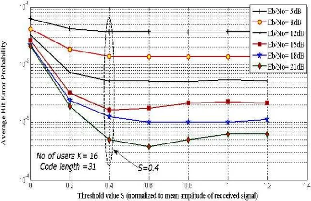
In this section the performance of the low complexity receiver is evaluated by computer simulations. The MC-DS-CDMA system described in Section 2 is used in simulation. A random binary sequences of processing gain N=31 are used for data spreading. The diversity order M is set = 2. The threshold value S is normalized to the mean amplitude value of the decision variable
Z
u. The total transmitted power is the same irrespective of the number of subcarriers, and a perfect power control system is assumed. The implementation complexity of the proposed scheme is discussed at the end of this Section.Figure 3. Dependence of average bit error probability of SA-PIC on the threshold value S (relative to mean amplitude value) for different Eb/No values, K= 1
Figure 4. Dependence of average bit error probability of SA-PIC on the threshold value S for different Eb/No values, number of users K= 26
Figure.5. Bit error probability of APIC, SA-PIC for S=0.4, K=10, 16, and 26
Figure 6 depicts the performance comparison of SA-PIC, MF, CPIC, and APIC schemes. It is clear that SA-PIC scheme outperforms both MF and CPIC schemes, while its performance almost the same as APIC scheme. However, the SA-PIC algorithm allows the implementation complexity to be notably reduced with respect to APIC scheme as discussed at the end of this section.
Figure 6. Comparisons of bit error probability for SA-PIC, CPIC, and APIC schemes for S=0.4, and K=16, 26 users
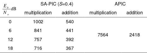
The SA-PIC scheme implementation complexity in terms of complex-valued operations is evaluated and compared with APIC under the same parameters. Table 1 shows the number of complex multiplication and addition per bit required to perform SA-PIC, and APIC schemes. The notations in the table are as follows. K denotes the number of users, M diversity order, N spreading gain, and L number of reliable signals. In Table 2, a numerical values of the number of multiplications and additions required by both schemes at. Different
E
b/
N
0 are calculatedestimated by simulation. Note that the complexity of the APIC scheme does not depend on
,
/
N
0E
b while in SA-PIC scheme, the complexity depends onE
b/
N
0because the value of L depends onE
b/
N
0. Table 2 shows that for practical values ofE
b/
N
0the complexity ofSA-PIC system is less than that one of the ASA-PIC scheme.
Table 1. Number of Complex Operations Required per Bit
Operation SA-PIC APIC
multiplication addition multiplication addition
Comparator and subtract
reliable signals MK L -
-Weights calculations NM[3(K-L)+2] NM[3(K-L-1] NM[3K+2] NM[3K-1]
Interference cancellation NM(K-L)[K-L-1] NM(K-L) NMK(K-1) NMK
Total
NM[(K-L)(K-L+2)+2]+MK
NM[4(K-L)-3]+L
NM[K(K-1)+3K+2] 4NMK-NM
Table 2. Numerical Values of Complex Operations Required per Bit
dB o b
N
E SA-PIC (S=0.4) APIC
multiplication addition multiplication addition
0 1002 540
7564 2418
6 841 441
12 757 392
18 716 367
5. Conclusion
A reduced complexity SA-PIC receiver with synchronous MC DS-CDMA system over Rayleigh fading channel has been investigated. The complexity of the receiver has been studied and compared with the APIC receiver. The performance of the receiver is evaluated by computer simulation and compared with the performance of different receivers. It has been shown that the performance of the low complexity SA-PIC receiver is same as APIC. The implementation complexity of this receiver in terms of number of multiplications and additions to be performed is lower than of the APIC receiver.
References
[1] Tingting L, Chenyang Y. Spectral Efficiency Comparison between MC-CDMA Two-Hop Relay Systems with Different Channel Information. IEEE Transactions on Vehicular Technology. 2012; 61(8): 3603-3614.
[2] Carl R. Multi-Carrier Technologies for Wireless Communication, Heidelberg: Springer-Verlag Berlin. 2010.
[3] Nagarajan V, Dananjayan P. Performance Analysis of MIMO MC-DS/CDMA System Using Chaotic Spreading Sequence. International Journal of Computer and Electrical Engineering, 2010; 2(2). [4] El-Mahdy A. Error probability analysis of multicarrier direct sequence code division multiple access
system under imperfect channel estimation and jamming in a Rayleigh fading channel. IET signal processing. 2010; 4(1): 89–101.
[5] Ho-Lung H, Hsing-Chung C. Multi-user detection in ultra-wideband multiple-access communications systems using an efficient heuristic algorithm.Scientific Research and Essays. 2012; 7(9): 1058-1069. [6] Han S, Lee J. Adaptive multi-stage parallel interference cancellation receiver for multi-rate DS-CDMA
system, IEICE Transactions on communications. 2004; 87-B (8): 2401–2405.
[7] Han S, Lee J. Performance of multi-rate DS-CDMA system with multi-stage partial parallel interference cancellation. Proceeding IEEE VTC 2000-Spring. 2000; 765-769.
[9] Xue G, J Weng, T Le-Ngoc, Tahar S. Adaptive multistage parallel interference cancellation for CDMA.IEEE j Select Areas Comm., 1999; 17 (10); 1815-1827.
[10] Fantacci R. Proposal of an Interference Cancellation Receiver with low complexity for DS-CDMA for mobile communication systems.IEEE Transactions on Vehicular Technology. 1999; 4: 1039-1046. [11] Baea J, Songb I, Wonb D. A selective and adaptive interference cancellation scheme for code division
multiple access systems. Signal Processing. 2003; 83: 259 – 273.
[12] Fantacci R, Marabissi D, Morosi S. Performance Analysis and Optimization of a Space-Time Selective PIC for CDMA Systems.IEEE Transactions on Wireless Communications. 2004; 3(2): 359-366 [13] Wang H, Ang K, Yen K, Chew Y.An adaptive PIC receiver with diversity combining foe MC-DS-CDMA
system. IEEE 58th Vehicular Technology Conference. 2003.
[14] Lin M. Performance of successive interference cancellation for a multicarrier DS/ CDMA system. Military Communications Conference Proceedings. 1999.
[15] Manohar S, Tikiya V, Annavajjala R, Chockalingam A. BER analysis of weighted interference cancellation in multicarrier DS-CDMA systems. Wireless Communications and Networking Conference (WCNC). 2006.
[16] Wang H, Yen K, Ang K, and Chew Y, Design and performance analysis of an adaptive receiver for multicarrier DS-CDMA. EURASIP Journal on Wireless Communications and Networking. 2007(2). [17] Hanzo L, Yang L, Kuan L, Yen K. Single-and Multi-carrier DS-CDMA: Multi-User Detection,