❘ ✁✂✄☎✆✝ ❘✞ ✆✟ ✁ ✠✝ ✡☎☎ ❘✆✡☛ ✞☞✌✞☞✍ ✞✌ ✍✎✏☞✆✑ ✞✡✒✟ ✞✌ ✍☎✑ ✆☞✝ ✂✓✝❘✄ A. Nussbergera, H. Grabnera, L. Van Goola
a
Computer Vision Laboratory, ETH Zurich, Switzerland - (nussberger, grabner, vangool)@vision.ee.ethz.ch
KEY WORDS:Aircraft, Detect and Avoid, Dynamic Flight, Object Tracking, Optical Sensors, Remotely Piloted Aircraft System
ABSTRACT:
Integrating drones into the civil airspace is one of the biggest challenges for civil aviation, responsible authorities and involved com-panies around the world in the upcoming years. For a full integration into non-segregated airspace such a system has to provide the capability to automatically detect and avoid other airspace users. Electro-optical cameras have proven to be an adequate sensor to detect all types of aerial objects, especially for smaller ones such as gliders or paragliders. Robust detection and tracking of approaching traffic on a potential collision course is the key component for a successful avoidance maneuver. In this paper we focus on the aerial object tracking during dynamic flight maneuvers of the own-ship where accurate attitude information corresponding to the camera images is essential. Because the ’detect and avoid’ functionality typically extends existing autopilot systems the received attitude measurements have unknown delays and dynamics. We present an efficient method to calculate the angular rates from a multi camera rig which we fuse with the delayed attitude measurements. This allows for estimating accurate absolute attitude angles for every camera frame. The proposed method is further integrated into an aerial object tracking framework. A detailed evaluation of the pipeline on real collision encounter scenarios shows that the multi camera rig based attitude estimation enables the correct tracking of approaching traffic during dynamic flight, at which the tracking framework previously failed.
1. INTRODUCTION
Within the upcoming decade aviation will be faced with one of their biggest challenges: the safe integration of Remotely Piloted Aircraft Systems (RPAS) into the civil airspace. The particu-lar roadmaps published by the U.S. and Europe in 2013 [Fed-eral Aviation Administration, 2013b, European RPAS Steering Group, 2013] plan a step by step integration depending on the airspace class and required technologies. The goal is to finally integrate RPAS by 2020-2030 into airspace classes where Visual Flight Rules (VFR) apply. One of the critical enabling technolo-gies to achieve this target is the availability of a technical sys-tem that replaces the human ’See and Avoid’ from manned avia-tion. According to recent publications such a ’Detect and Avoid’ (DAA) system shall providean equivalent level of safety com-pared to a human pilot[International Civil Aviation Organiza-tion, 2011, Federal Aviation AdministraOrganiza-tion, 2013a].
A typical Detect and Avoid system has to deal with so called co-operative and non-coco-operative traffic. While coco-operative traffic usually transmits its own position via transponder based tech-nologies (e.g. ADS-B1), non-cooperative traffic has to be de-tected in a different way. Most of the current research activities with focus on non-cooperative traffic detection and tracking ei-ther use a RADAR [Wolfe, 2003, Korn and Edinger, 2008, Owen et al., 2014], electro optical (EO) sensors [Utt et al., 2004, Carnie et al., 2006,Dey et al., 2011,Mejias et al., 2012,Nussberger et al., 2014] or a combination of them [Forlenza et al., 2012]. While RADAR allows to measure the distance to a given object it might fail to detect small airspace users such as gliders or paraglid-ers. EO sensors on the other hand consume much less power and space but estimating a distance to the detected object is non-trivial. Both technologies have in common that the detection of traffic in front of terrain is a very challenging task usually re-sulting in a large number of false tracks. Therefore most of the published results are limited to detect and track aerial objects in 1ADS-B is a cooperative, standardized technology to transmit the own position and velocity at a fixed interval. The maximum range is given by the aircraft transponder power and can exceed 100 km.
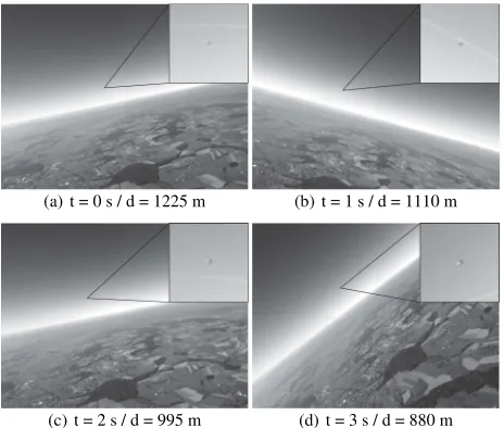
✭✔ ✕t = 0 s / d = 1225 m ✭✖ ✕t = 1 s / d = 1110 m
✭✗✕t = 2 s / d = 995 m ✭✘✕t = 3 s / d = 880 m Figure 1: Example images of an approaching traffic aircraft recorded from an aerial platform during a dynamic flight maneu-ver. The upper right corner shows a magnified cutout of the in-coming traffic. Notice that sky as background eases detection. the sky part of the sensor, a strong limitation when operating at low altitude or in a mountainous area.
x
y 110◦
126◦
✙✚✛Multi camera rig ✙✜✛Custom nose-pod
Figure 2: Overview of the multi camera rig in the sensor nose-pod. As shown in the left figure, only two of the possible four cameras are mounted in the pod which was sufficient to record the relevant collision scenarios and cover approximately half of the recommended field of view for a Detect and Avoid system [ASTM International, 2007]:±110◦
horizontally and±15◦
ver-tically.
non-overlapping sensors can easily be integrated by a proper cal-ibration. However, the proposed framework is heavily depending on accurate attitude measurements because otherwise new detec-tions will be projected to inconsistent posidetec-tions on the unit sphere resulting in multiple tracks or no track at all. While this problem is negligible during level flight and smooth maneuvers, it is a se-rious issue to consider for large sensor displacements in between consecutive frames. This is the issue dealt with in this paper.
Large sensor displacements usually occur within high dynamic flight maneuvers, e.g. due to a sudden avoidance maneuver. It is obvious that losing track of the aerial object the system is cur-rently avoiding is very unfavorable in terms of situational aware-ness and conflict resolution. The availability of high precision attitude angles corresponding to the sensor sample rates from the DAA system is a critical issue in RPAS DAA systems. The DAA functionality is typically integrated as an additional sub-system connected to the aircraft autopilot as shown in Figure 3. This sys-tem architecture is a result of existing RPAS functionality, safety and certification requirements. In addition it supports the spe-cific interfaces and high processing power required for the DAA sensors - especially when using optical cameras or a RADAR. Within this configuration all meta data such as position and atti-tude information is provided by the aircraft autopilot. Depending on the interface the (third-party) autopilot manufacturer provides, this will introduce unknown delays and dynamics.
A lot of research has been done in the area of visual odome-try (VO) [Nist´er et al., 2004, Kneip et al., 2011, Forster et al., 2014] or simultaneous localization and mapping (SLAM) [Davi-son, 2003, Klein and Murray, 2007, Engel et al., 2014] where typ-ically the vehicle rotation is estimated together with its transla-tion. However, these methods either require high frame rate cam-eras or they are computationally expensive, especially if we are only interested in the rotational component in between consecu-tive frames.
❋✢ ✣✤ ✥✦3: Typical Detect and Avoid System Architecture. The
aircraft autopilot is directly connected to a number of navigation sensors which are fused to a consistent navigation solution. The Detect and Avoid sub-system receives its meta data such as po-sition and attitude data from the autopilot which introduces un-known delays and dynamics.
In this paper we present an efficient approach to extract the air-craft angular rates from a multi camera rig. By fusing these angu-lar rates with delayed, absolute attitude angles received from the RPAS autopilot we estimate the inter-frame delta angles while keeping the global attitude drift minimal. The proposed atti-tude estimation method is further integrated into the aerial object tracking framework where we will show improved results based on the same dataset as used in [Nussberger et al., 2015] and ad-ditional challenging high dynamic maneuver scenarios. Within these additional scenarios the pilot was manually flying a so called wingrock where the aircraft continuously banks from the left to the right and reverse to induce large ego-motion.
The paper is structured as follows. Section 2. introduces the an-gular rate estimation based on the multi camera rig and describes the proposed filter to fuse the angular rates with delayed absolute attitude measurements. In Section 3. we show a detailed evalua-tion of the proposed attitude estimaevalua-tion filter. Secevalua-tion 4. shows the attitude estimation applied to aerial object tracking and in Section 5. we conclude the paper.
2. ATTITUDE ESTIMATION
Accurate attitude angles are a key component to efficient and ro-bust tracking in aerial images. In this Section we introduce a method to efficiently calculate the aircraft angular rates from a multi camera rig. In addition we show how to fuse these relative angular rates with delayed, absolute attitude measurements.
2.1 Requirements for a Pure Rotation Transformation
One of the main differences between the VO and SLAM research compared to our work is that they usually focus on micro aerial vehicles (MAVs) operating close to the ground. In contrast, the presented experimental DAA system is based on a general avia-tion (GA) sized RPAS typically operating at altitudes way beyond 500 m above ground. This is exactly the key property we will use for the efficient calculation of the angular rates from the multi camera rig. With a minimum altitude of 500 m above ground we can assume a pure rotation in between consecutive frames under the conditions explained below, i.e. conditions under which the own-ships forward translation has no effect on the image.
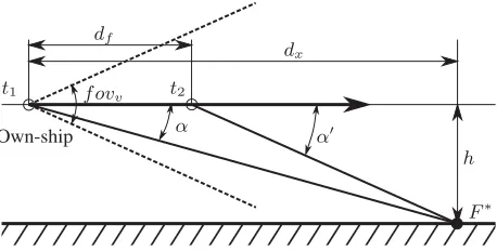
For a simplified analysis we assume an aircraft as shown in Fig-ure 4 at constant altitude and speed with a forward looking cam-era with given vertical angular resolution
θv=
Vertical field of view
Number of vertical pixels. (1)
At time instantt1the camera observes a stationary feature on the
groundF∗
under an angleα. In the next frame att2 the same
feature will be visible under an angleα′
. For the pure rotation case we have to make sure the feature is projected to the same pixel for both time instances. This is valid as long as the angular change of the feature in between the two frames is smaller than the vertical camera resolution:
α′
−α≤θv. (2)
With the horizontal distancedxof the featureF
Own-ship α
❋✢ ✣✤ ✥✦4: Sketch of an aircraft flying at constant altitude and
speed parallel to the ground. The camera with vertical field of viewf ovvobserves a stationary featureF
∗
at two consecutive frames at time instancest1 andt2under the corresponding
an-glesαandα′
. If the angular change in between these two angles is smaller than the camera angular resolutionθvwe have a pure
rotation in between the two consecutive frames.
After combining these equations we can express the minimum required altitude for the pure rotation assumption to hold, given the aircraft speedvacf t, the camera vertical angular resolutionθv
and a given ’feature angle’α:
hmin≥
tan(α+θv)·tan(α)·vacf t·(t2−t1) tan(α+θv)−tan(α)
. (5)
In Table 1 we show different examples of parameters with the corresponding resulting minimum altitude for common aircraft speeds of 100 and 150 knots. In addition to the original verti-cal image size of 2472 pixels we also provide results for down-sampled images. They show that the assumption of a pure ro-tation in between two consecutive frames is satisfied as soon as we use a properly down-sampled image and the aircraft operates above approximately 500 m.
Parameters Result
vacf t pxver θv α hmin
[knots] [pixel] [deg/px] [deg] [meter]
100 2472 0.02 10 214
100 2472 0.02 20 829
100 2472 0.02 30 1772
100 2472 0.02 40 2927
100 618 0.08 10 54
150 618 0.08 40 1106
Table 1: Comparison of different parameter configurations re-quired for the pure rotation assumption in between two consecu-tive frames and the resulting minimal required altitudehmin:
air-craft speedvacf t, vertical resolution in pixelpxver, vertical
an-gular resolutionθvand feature angleα. In addition to the values
specified in the table we assume a constant frame rate of 20 fps and a vertical field of view of51◦
.
2.2 Multi Camera Rig Angular Rate Estimation
The main problem with the current tracking framework is its re-quirement for accurate attitude measurements which have to cor-respond precisely to the actual camera motion. Therefore we will directly use the camera as a sensor itself. Because the experimen-tal DAA system is based on multiple cameras we are even able to integrate the motion information from all of them. For the an-gular rate estimation from the multi camera rig we use the same idea of a unit sphere centered at the current aircraft position as proposed for the tracking. In contrast to the tracking framework the unit sphere is defined with respect to the local aircraft body reference frame (see Figure 5) instead of the local navigation ref-erence frame. Note that for the following steps we assume the multi camera rig to be fully calibrated. Based on the results from the previous subsection we implemented the angular rate estima-tion as follows:
1. For every camera we down-sample the current frame to re-duce the overall computational cost. As shown in Table 1 the resulting angular resolution is still below0.1◦
even if the image is down-sampled by a factor of four.
2. In the next step, SURF features are extracted. Most of them obviously from the heavily textured terrain part of the im-ages. Because of the available multi camera setup the ter-rain can be expected to be visible in at least two of the four cameras during all common flight maneuvers.
3. The detected features are now projected onto the surface of the unit sphere using the corresponding extrinsic cam-era calibration as shown in Figure 5. These features are then matched in between the unit sphere of the current time step and the previous one, which results in a set of point corre-spondences related by a rotation matrixR3x3.
4. Based on this set of point correspondences we calculateR3x3
according to [Challis, 1995] using a RANSAC based ap-proach to account for possible outliers. The rotation matrix we get yields the delta angles from the previous to the cur-rent frame. From the rotation matrix we extract the Euler angles. By dividing them with the sample time we finally get the angular ratesωcam= [p, q, r]⊺.
A brief overview of the complete angular rate estimation algo-rithm in pseudo code is shown in Figure 6.
N
❋✢✣ ✤ ✥✦5: Mapping of features from the ground onto the surface
♣✧★✩✪ ✫✬✧✪ESTIMATEANGULARRATE Initializeus1
forevery camerado
Down-sample current frame Extract SURF features Project features ontous1
end for
Match features fromus1andus2 Calculateωcam←R3x3←matches Backupus2←us1
returnωcam end procedure
Figure 6: Basic algorithm to estimate the angular rateωcamwith the multi camera rig. The features of the current camera frames are projected onto the first unit sphereus1, whereas the features from the previous time step are available inus2.
2.3 Fusion of Camera Angular Rates with Delayed Absolute Attitude Measurements
With the estimated angular rates from the multi camera rig and the available (but delayed) absolute attitude measurement from the aircraft autopilot we setup an indirect Kalman filter to get a delay compensated absolute attitude estimate. For the attitude representation we use a quaternion based approach. This allows a straight forward integration of angular rates and avoids common issues such as ’gimbal lock’ when using Euler Angles. Note that we use the Hamilton notation where the first value of the quater-nion corresponds to the scalar component:q= [q0,q1−3]⊺.
The system model is based on the integration of the angular rates with the assumption ofω˙ = 0, driven by Gaussian noise. While this is not strictly correct, it is an acceptable approximation be-cause we directly measure this value byωcam. A different ap-proach could be to directly useωcamas input but then we would have to take special care if for once the calculation ofωcamfails. The continuous time system state dynamics ar given as
˙
q= 1
2·Q(ω)·q (6)
˙
ω=nω (7)
whereQis the quaternion matrix function [Diebel, 2006] and
nωthe angular acceleration noise. As already stated before we use an indirect Kalman filter where the errors are part of the filter state and the error dynamics are modeled. The correct attitude is calculated by multiplying the estimatedqˆwith an error rotation
δq. Therefore the resulting error model is given by
δq= ˆq−1
⊗q (8)
∆ω=ω−ωˆ (9)
Because the angular errors are usually small, we are able to apply the small angle approximation for quaternions
δq≈ which reduces the number of parameters to three and avoids an overdetermined attitude representation within the filter. This re-sults in the error state vector
x6×1=
with the corresponding continuous time error state dynamics
δθ˙ =−ω×·δθ (12)
∆ ˙ω=nω (13)
whereω×is the skew symmetric matrix ofω. In [Trawny and
Roumeliotis, 2005], a detailed derivation of Equation (12) and the corresponding discrete formulation is presented.
The prediction step of the filter is calculated according to the fol-lowing equations whereIis the identity matrix,Pˆ the estimated covariance,Fthe discretized error system matrix andV the error process noise. For the integration of the quaternion a zero order approximation is used. Within the filter update step we have to incorporate the delayed attitude measurement. The classical approach would be to aug-ment the filter state [Tasoulis et al., 2007] and setup the measure-ment matrixHaccordingly. In our setup we avoid increasing the filter state by buffering previous states. Instead we just save the history of angular rates to project the delayed attitude measure-ment to the current time step. Note that we assume a constant delay for the attitude measurements which we determine once from recorded data. If the delay is not constant we could estimate it e.g. by calculating the cross correlation [Kelly and Sukhatme, 2010] in between the angular rates from the camera and the ones from the aircraft autopilot. To calculate the filter update, we pro-ceed as follows:
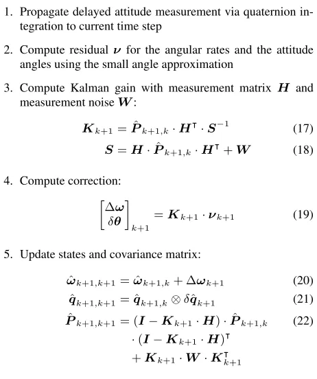
1. Propagate delayed attitude measurement via quaternion in-tegration to current time step
2. Compute residualν for the angular rates and the attitude angles using the small angle approximation
3. Compute Kalman gain with measurement matrix H and measurement noiseW:
5. Update states and covariance matrix:
ˆ
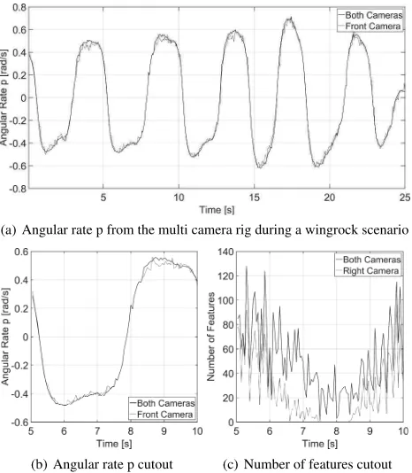
✸✮ ✯ Multi Camera Rig Angular Rate Estimation Analysis The angular rate calculation from the multi camera rig is heavily relying on robust features in between consecutive frames. Espe-cially for dynamic flight maneuvers the results improve with a uniform distribution of features on the unit sphere. Therefore the more cameras provide features, the better. As shown in Figure 2, the current multi camera rig configuration has two built-in cam-eras of the planned four. In Figure 7 we show example plots of the angular rate p around the roll axis calculated from the cam-era rig for one of the wingrock scenarios. Results are presented for the front camera only and for both cameras. We can see that especially for the large displacements at around±0.6rad/s the accuracy is increased if the second camera is included. On the other hand the accuracy usually drops if the aircraft banks to the left because then the right camera points to the sky and the two left cameras are not yet available in the camera rig. This can re-sult in errors in the uprising part of the angular rate p as shown in Figure 7(b). The corresponding number of features over time is given by Figure 7(c), where a significant drop in number of features for the right camera is visible in between 6.5 and 8.5 seconds. This is exactly while the camera is pointing to the blue sky.
3.2 Attitude Estimation Filter Analysis
The attitude data from the aircraft autopilot is assumed to have a constant delay. By fusing these delayed attitude measurements with the angular rates from the multi camera rig according to the method presented in Subsection 2.3, we can compensate for the delay as shown in Figure 8. There we show a comparison of the roll angle from the aircraft autopilot and the output from the filter. The roll angle is obviously the most significant angle during a wingrock. Because the delay is rather small compared to the scenario duration, two zoomed cutouts are shown.
✙✚✛Angular rate p from the multi camera rig during a wingrock scenario
✙✜✛Angular rate p cutout ✙✰✛Number of features cutout Figure 7: Angular rate of the roll axis calculated from the multi camera rig during a wingrock scenario. Results are shown for the front camera only and both cameras. As shown in the bottom right figure, the influence of the right camera drops if the aircraft banks to the left.
❋✢✣ ✤ ✥✦8: Comparison of the roll angle from the aircraft and the attitude filter during a wingrock scenario with two cutouts at 12.7 and 14.7 seconds respectively.
4. ATTITUDE ESTIMATION APPLIED TO AERIAL OBJECT TRACKING
The motivation for calculating the angular rates from the multi camera rig and fusing them with the delayed attitude measure-ments from the RPAS autopilot is to get accurate absolute attitude angles corresponding to the current camera frame. This enables improved tracking performance during highly dynamic maneu-vers, e.g. during an automatic avoidance. In this section we give a brief overview of the extended aerial object tracking framework and show a detailed evaluation based on existing and new scenar-ios.
4.1 Extended Aerial Object Tracking Framework
❙✩✪✱ ✲✧✳ ★✴ Results without Results with
Attitude Estimation Filter Attitude Estimation Filter
Type Background Distance TTC False
Tracks Distance TTC
False Tracks
N Wingrock Sky fails - - 1932 m 16.0 s 0
O Wingrock Terrain fails - - 1730 m 15.3 s 0
P Wingrock Sky fails - - 1908 m 17.9 s 0
Q Wingrock Terrain fails - - 921 m 9.1 s 1
Average - - - 1623 m 14.6 s
-Table 2: Evaluation of the aerial object tracking framework with the attitude estimation filter. For each scenario we show the remaining distance once the incoming traffic aircraft is successfully tracked, the remaining time to collision (TTC) and the total number of false tracks during the scenario. Note that for the evaluation without attitude estimation filter the traffic aircraft is detected as well, but the tracking framework fails to create a consistent track.
4.2 Scenario Evaluation
We evaluate the extended aerial object tracking framework on the existingScenarios A-Mand four new wingrockScenarios N-Q. Those scenarios are based on a standard head-on encounter while the own-ship continuously banks from left to right and reverse to induce heavy egomotion. In Table 2 the results are summarized and compared to the aerial object tracking framework without the attitude estimation extension. For each scenario the initial dis-tance of the traffic aircraft with the corresponding remaining time to collision (TTC) is shown, once a valid track is available. The TTC is calculated based on the time once the track is declared valid and the time of the closest point of approach, assuming a constant closing speed. As a third performance measure we indi-cate the total number of false tracks during the complete scenario. For theScenarios A-Mwe achieve the same results as published in [Nussberger et al., 2015] which is a reasonable outcome be-cause all of them are level flight. Therefore we do not repeat those results in Table 2.
Based on one of the new wingrock scenarios (Scenario P) we will now further analyze the dramatically improved tracking perfor-mance within high dynamic maneuvers. In Figure 10 the tracks from the tracking sphere are visualized as 2D surface plots. If the delayed attitude measurements are directly used, the tracker fails to create a consistent track and multiple individual tracks are ini-tialized. Even worse, there are large gaps in between where the
Attitude Camera
Horizon Estimation
GPS
Tracker
DTM Lens Flare
Detection
(delayed) (delayed)
Attitude Estimation
Detection
Object Detection Fusion
❋✢ ✣✤ ✥✦9: Aerial object tracking framework presented by
[Nuss-berger et al., 2015], extended with the Attitude Estimation block to compensate for the delayed attitude measurements from the aircraft autopilot. The resulting offset from the delayed GPS po-sition is not critical and can be neglected.
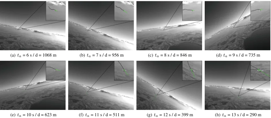
tracking completely fails. This is a serious issue if the output of the optical DAA system shall be used further for an automatic avoidance maneuver. As soon as the attitude estimation filter is enabled as shown in the lower part of the figure, the tracker cor-rectly maintains one single track for the approaching traffic air-craft - even though the own-ship continuously banks from left to right and reverse. Corresponding example frames forScenario N andPwith disabled and enabled attitude estimation filter are pre-sented in Figure 12. ForScenario Owhere the approaching traf-fic has to be detected in front of terrain we show a series of eight frames taken at a one second interval in Figure 11. As results show the track is declared valid at an initial distance of∼1700 m
✙✚✛Attitude Estimation disabled
✙ ✜✛Attitude Estimation enabled
✙✚✛ta= 6 s / d = 1068 m ✙✜✛ta= 7 s / d = 956 m ✙✰✛ta= 8 s / d = 846 m ✙✵✛ta= 9 s / d = 735 m
✙✶✛ta= 10 s / d = 623 m ✙✷✛ta= 11 s / d = 511 m ✙✹✛ta= 12 s / d = 399 m ✙✺✛ta= 13 s / d = 290 m Figure 11: Example frames from the wingrockScenario Oat different time steps. The track is shown with its one second prediction in green and the track history in black. The timetaindicates the total ’alive time’ of the track. From frame (a) to (f) it can easily be seen that the period of the wingrock maneuver was approximately five seconds. This figure is best viewed in color.
and correctly maintained for the rest of the scenario. Detecting approaching traffic in front of terrain is generally more challeng-ing compared to an object within the sky part of the image. One of the reasons is the typically small contrast between the traffic and the terrain.
The results achieved for the second scenario with terrain as back-ground (Scenario Q) warrant a separate discussion because the initial track distance and the remaining TTC are significantly lower compared to the other scenarios. This is basically a result of the extreme environmental conditions: the sun is located in front but slightly above the camera resulting in heavy lens flare. The hori-zon is hazy and directly reflecting the sunlight which results in an exceptional dynamic range (note that this scenario was recorded with a bit depth of 8-bit) and the traffic aircraft initially approaches in front of a dark forest. As a result of this the traffic is first de-tected shortly before it is at 1000 m. Once detections are available
✙ ✚✛Scenario N: AEF off ✙✜✛Scenario N: AEF on
✙✰✛Scenario P: AEF off ✙✵✛Scenario P: AEF on Figure 12: Example frames fromScenario NandPwith disabled (AEF off) and enabled (AEF on) attitude estimation filter. Multi-ple tracks are created if the AEF is disabled because new detec-tions are mapped to wrong posidetec-tions on the tracking sphere (best viewed in color).
the tracker is able to successfully track the object although lens flares repeatedly pass through the track due to the continuously changing roll angle. An example frame of the tracker output is shown in Figure 13.
5. CONCLUSIONS
We presented an efficient solution to calculate the angular rates of an aircraft from a multi camera rig based on the assumption of a pure rotation in between consecutive frames. By analyzing the influencing parameters we have shown that the pure rotation assumption is fulfilled as soon as the aircraft is operated at least 500 m above ground. Typical operation altitudes are usually way beyond 500 m. With an indirect Kalman filter the angular rates are fused with delayed absolute attitude measurements available from a third-party RPAS autopilot. This allows estimating ac-curate absolute attitude angles corresponding to the current cam-era frames. We integrated the proposed attitude estimation filter
✢ ✐✻ ✼an existing aerial object tracking framework and show that with this extension of the pipeline aerial objects are not only cor-rectly tracked during level flight but also within high dynamic flight maneuvers. This is a key component for any EO DAA sys-tem because the maximum range where aerial objects can be de-tected might be smaller compared to other technologies. There-fore an automatic avoidance has to rely on consistent tracks, es-pecially if an aggressive avoidance maneuver has to be executed due to nearby traffic. With the presented approach the aerial ob-ject tracking framework can be integrated into a third-party RPAS without the necessity of installing additional redundant sensors and the requirements on sensor data quality can be relaxed.
ACKNOWLEDGMENTS
This work is supported by armasuisse Science and Technology, affiliated with the Swiss Federal Department of Defense, Civil Protection and Sport.
REFERENCES
ASTM International, 2007. Standard specification for design and performance of an airborne sense-and-avoid system.
Carnie, R., Walker, R. and Corke, P., 2006. Image processing algorithms for UAV ”sense and avoid”. In: Proc. of International Conference on Robotics and Automation.
Challis, J. H., 1995. A procedure for determining rigid body transformation parameters. Journal of Biomechanics.
Davison, A. J., 2003. Real-time simultaneous localisation and mapping with a single camera. In: Proc of International Confer-ence on Computer Vision.
Dey, D., Geyer, C., Singh, S. and Digioia, M., 2011. A cascaded method to detect aircraft in video imagery. International Journal of Robotics Research 30, pp. 1527–1540.
Diebel, J., 2006. Representing attitude: Euler angles, unit quater-nions, and rotation vectors. Technical report, Stanford University. Engel, J., Sch¨ops, T. and Cremers, D., 2014. LSD-SLAM: Large-scale direct monocular SLAM. In: Proc. of European Conference on Computer Vision.
European RPAS Steering Group, 2013. Roadmap for the integra-tion of civil remotely-piloted aircraft systems into the european aviation system.
Federal Aviation Administration, 2013a. FAA order JO 7610.4 special operations.
Federal Aviation Administration, 2013b. Integration of civil un-manned aircraft systems (UAS) in the national airspace system (NAS) roadmap.
Forlenza, L., Fasano, G., Accardo, D. and Moccia, A., 2012. Flight performance analysis of an image processing algorithm for integrated sense-and-avoid systems. International Journal of Aerospace Engineering.
Forster, C., Pizzoli, M. and Scaramuzza, D., 2014. SVO: Fast semi-direct monocular visual odometry. In: Proc. of International Conference on Robotics and Automation.
International Civil Aviation Organization, 2011. ICAO cir 328, unmanned aircraft systems (UAS).
Kelly, J. and Sukhatme, G. S., 2010. A general framework for temporal calibration of multiple proprioceptive and exteroceptive sensors. In: Proc. of International Symposium on Experimental Robotics.
Klein, G. and Murray, D., 2007. Parallel tracking and mapping for small ar workspaces. In: Proc. of International Symposium on Mixed and Augmented Reality.
Kneip, L., Chli, M. and Siegwart, R., 2011. Robust real-time visual odometry with a single camera and an IMU. In: Proc. of British Machine Vision Conference.
Korn, B. and Edinger, C., 2008. UAS in civil airspace: Demon-strating ”sense and avoid ” capabilities in flight trials. In: Proc. of Digital Avionics Systems Conference.
Mejias, L., Lai, J. S. and Ford, J. J., 2012. Flight trial of an electro-optical sense-and-avoid system. In: Proc. of International Congress of the Aeronautical Sciences.
Nist´er, D., Naroditsky, O. and Bergen, J., 2004. Visual odom-etry. In: Proc. of Conference on Computer Vision and Pattern Recognition.
Nussberger, A., Grabner, H. and Van Gool, L., 2014. Aerial ob-ject tracking from an airborne platform. In: Proc. of International Conference on Unmanned Aircraft Systems.
Nussberger, A., Grabner, H. and Van Gool, L., 2015. Robust aerial object tracking in images with lens flare. In: Proc. of Inter-national Conference on Robotics and Automation.
Owen, M., Duffy, S. and Edwards, M., 2014. Unmanned aircraft sense and avoid radar: Surrogate flight testing performance eval-uation. In: Proc. of Radar Conference.
Tasoulis, D. K., Adams, N. M. and Hand, D. J., 2007. Delayed measurements and the Kalman filter. Technical report, Imperial College London, Dept. of Math.
Trawny, N. and Roumeliotis, S. I., 2005. Indirect Kalman filter for 3D attitude estimation. Technical report, University of Min-nesota, Dept. of Comp. Sci. & Eng.
Utt, J., McCalmont, J. and Deschenes, M., 2004. Test and integra-tion of a detect and avoid system. In: Proc. of AIAA ”Unmanned Unlimited” Technical Conference.
![Figure 2: Overview of the multi camera rig in the sensor nose-pod. As shown in the left figure, only two of the possible fourcameras are mounted in the pod which was sufficient to recordthe relevant collision scenarios and cover approximately half ofthe recommended field of view for a Detect and Avoid system[ASTM International, 2007]: ±110◦ horizontally and ±15◦ ver-tically.](https://thumb-ap.123doks.com/thumbv2/123dok/3210813.1394079/2.595.58.290.69.196/fourcameras-sufcient-collision-scenarios-approximately-recommended-international-horizontally.webp)