THE PERFORMANCE ANALYSIS OF AN INDOOR MOBILE MAPPING SYSTEM WITH
RGB-D SENSOR
G.J. Tsai a, K.W. Chiang a, C.H. Chu a, Y.L. Chen a, N. El-Sheimy b, A. Habib c
a Dept. of Geomatics Engineering, National Cheng-Kung University, No. 1, Daxue Road, East District, Tainan City, [email protected]
b Dept. of Geomatics Engineering, The University of Calgary, 2500 University Dr NW, Calgary, AB T2N 1N4, Canada, [email protected]
c Dept. of Civil Engineering, The University of Purdue, 610 Purdue Mall, West Lafayette, IN 47907, United States, [email protected]
KEY WORDS: Mobile Mapping Systems, SLAM, Direct Georeferenced (DG), robot, indoor mapping, Position and Orientation System
ABSTRACT:
Over the years, Mobile Mapping Systems (MMSs) have been widely applied to urban mapping, path management and monitoring and cyber city, etc. The key concept of mobile mapping is based on positioning technology and photogrammetry. In order to achieve the integration, multi-sensor integrated mapping technology has clearly established. In recent years, the robotic technology has been rapidly developed. The other mapping technology that is on the basis of low-cost sensor has generally used in robotic system, it is known as the Simultaneous Localization and Mapping (SLAM). The objective of this study is developed a prototype of indoor MMS for mobile mapping applications, especially to reduce the costs and enhance the efficiency of data collection and validation of direct georeferenced (DG) performance. The proposed indoor MMS is composed of a tactical grade Inertial Measurement Unit (IMU), the Kinect RGB-D sensor and light detection, ranging (LIDAR) and robot. In summary, this paper designs the payload for indoor MMS to generate the floor plan. In first session, it concentrates on comparing the different positioning algorithms in the indoor environment. Next, the indoor plans are generated by two sensors, Kinect RGB-D sensor LIDAR on robot. Moreover, the generated floor plan will compare with the known plan for both validation and verification.
1. INTRODUCTIO
Mobile mapping refers to a means of collecting geospatial data using mapping sensors that are mounted on a mobile platform. The idea of mobile mapping is basically implemented by capturing more than one images which includes the same feature point from different location. Then, the 3D spatial information of objects will be calculated and measured with respect to the mapping frame (Tao and Li, 2007). Besides, multi-sensor is corresponding with multi-platform that mounted on a various vehicles, such as automobile, aircraft, water-based vessels and unmanned aerial vehicle (UAV). In the early 2000s, a lot of land vehicular-based mobile mapping systems have been utilized in commercial applications. It means that MMS is able to meet the demand of spatial information system operators for rapid spatial data acquisition. However, most of land vehicular based MMSs has to spend lots of cost on developing different kind of system so that limiting their growth. In addition, the primary limitation of such land vehicular-based systems in terms of operation flexibility is the dependence of the availability and quality of road networks.
Because of the increasing demand for indoor accurate maps, the MMS is shifting to the next phase, indoor environment. This application is used in emergency, indoor navigation, Location Based Service (LBS), etc. SLAM is the algorithm that builds or updates the map of an unknown situation and simultaneously tracks the position and attitude of vehicle. In outdoor environment, GNSS is regarded as the primary positioning sensor. However, the indoor environment is more difficult for localization. Therefore, to solve this problem, most of SLAM algorithms always use several types of sensors, such as camera,
IMU, laser scanner and based on the robotic configuration. The core integrating algorithm includes Kalman filters, particle filters and other image processing technologies. In the field of SLAM applications, most of algorithms rely on using landmark-based and raw-data approaches. In frame-to-frame registration SLAM, it is required visual feature points as an initial transformation state for the Iterative Closet Point (ICP) based on the RGB-D sensors (Litomisky, 2012). On the other hand, 2D SLAM with LIDAR that integrated with IMU aiding navigation system is also improved the accuracy of planar map (Kohlbrecher, 2011). The visual (VSLAM) is one of the SLAM algorithms that uses continuous images from single camera or stereo cameras and extracting the feature point to calculate the relationship between two images (Karlsson, 2005). However, the problem is that it needs extra expense to set up some landmarks and the positioning accuracy relies on the density of those marks. It is not very appropriate when robot is searching and exploring the unknown environment.
The core localization algorithm is an inertial navigation system (INS). An INS is a self-contained navigation technique in which measurements provided by accelerometers and gyroscopes are used to track the position and orientation of an object relative to a known starting point, orientation and velocity. In addition, GNSS is a universal, all-weather, world-wide positioning system that provides time, position and velocity data. Both systems can be used as stand-alone navigation tools or in conjunction with other sensors for various purposes. Moreover, the integration of GNSS and INS can overcome problems with environments like urban canyons, forests and indoor settings where GNSS alone cannot provide service. In the classical approach, the KF is applied in real-time applications to fuse
different data from various sensors while optimal smoothing is applied in the post-mission mode. The basic idea of using the KF in INS/GNSS integration is to fuse independent and redundant sources of navigation information with a reference navigation solution to obtain an optimal estimate of navigation states, such as position, velocity and orientation. The primary concept is to integrated different type of sensor. In indoor environment, the indoor MMS localization will switch the other locating mode based on taking the place of GNSS. The visual odometry is an auxiliary algorithm that determining the position and orientation by processing serial images. In this research, the indoor MMS is composed of the SLAM technology and INS/GNSS and can build the indoor floor plan for indoor navigation application.
In order to generate the floor plan with high accuracy in real-time solution, the less computing real-time and dataset are necessary. Moreover, the robust loop-closure is also the primary issue to be improved. The approach that transformed 3D point cloud to 2D floor plan is implemented by using histogram of point density and Hough transform algorithm for line segments extracted (Okorn, 2009). Turner proposed the watertight model from 2D grid map or 3D point-clouds and triangulating the 2D sampling to interior or exterior set (Turner, 2014). Rao-Blackwellized particle filters (RBPF) is one of popular algorithm in recent years. It have been adopted as an effective method to solve the SLAM problem (Grisetti, 2007).
In indoor mapping system, most of configuration is included the RGB-D sensor and laser scanner. To achieve the high accurate application and control, the Inertial Measurement Unit is always used for positioning and attitude estimation. Using Kinect sensor for mobile robot has become more popular. The mobile robot equipped with Kinect and laser scanner based on wheel odometry can easy implement the 2D and 3D SLAM (Oliver, 2012). Unmanned Aerial Vehicle (UAV) has the great potential to indoor mapping and navigation because of its flexibility. The laser scanner and mono-camera are standard accessories for UAV indoor mapping system (Wang, 2013). In order to achieve the 3D indoor mapping, most of platform also uses the RGB-D sensor. The system also included the IMU sensor to estimate the six-degree-freedom pose in GPS-denied environment (Morris, 2010). The system of indoor UAV is enable to flight in cluttered environment and illuminate the scene as well (Bachrach, 2012). Besides, the indoor portable mapping is also proposed for human. It creates the payload for human-portable mapping system and mapping of different floor (Fallon, 2012).
According to previous research, this study proposes the data processing modules including integrated Position and Orientation System (POS) module, and visual base module. Based on these approaches, we designs the payload for indoor MMS to generate the floor plan and compare to different sensors and positioning algorithms.
2. PAYLOAD DESIGN AND IMPLEMENTATION
2.1 Robotic System and Architecture
In our research, the algorithm and the configuration is based on the Robot Operating System (ROS). All the software is installed on the control notebook. The Figure 1 shows the ROS Architecture. The robot is the Turtlebot2 and the mobile base is kobuki base. The control laptop connect to two different sensor and robot base to implement the indoor mobile mapping.
Figure 1. The indoor robot system and Architecture
2.2 Payload Design
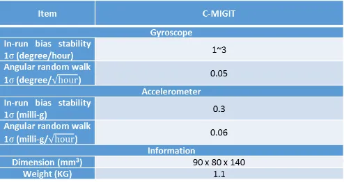
To implement the indoor MMS, the prototype of this paper is included the tactical grade Inertial Measurement Unit (IMU), the Kinect RGB-D sensor and light detection, ranging (LIDAR). The hardware consists of RGB-D Kinect sensor, Hokuyo laser scanner (Hokuyo UST-20 LX) and IMU. The payload is demonstrated in Figure2. The Table 1 shows the specification of IMU for indoor pose estimation.
Figure 2. The payload design of indoor MMS prototype
Table 1. Specification of IMU
3. INDOOR POSITIONING SYSTEM
In this paper, three kind of positioning algorithms will be implemented and compared. The positioning algorithms are INS Direct Georeferencing, Robotic wheel odometry and Visual odometry.
3.1 INS Direct Georeferencing
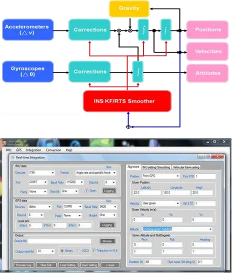
For a georeferencing process which puts POS stamps on images and a measurement process that obtains three-dimensional coordinates of all important features. INS system, several architectures for INS/GNSS integration implementations are known. The most common integration scheme used today is loosely-coupled (LC) integration scheme. It is the simplest way of integrating a GNSS processing engine into an integrated navigation system. However, GNSS is not useful in indoor environment. To improve the indoor POS estimation, filtering is used in the first step, an optimal smoothing method, such as the Rauch-Tung-Striebel (RTS) backward smoother, can be applied. It uses filtered results and their covariance as a first approximation. This approximation is improved by using additional data that was not used in the filtering process. As the integrated scheme and the software shown in Figure 3, the KF/RTS smoother integrate different kind of sensor and with the well self-contained POS results. The
Figure 3. INS integrated scheme and the software developed for indoor MMS
3.2 Robotic Wheel Odometry
Wheel odometry is one of the important information for robot position estimation. The odometry information is measured from wheel rotation. It is known as a function of time from two wheels on a fix axle. The position and heading information can be calculated by the function of time. By combining the gyroscope embedded in robot, the performance of robot position will achieve higher accuracy (Chong, 1997).
3.3 Visual Odometry
In computer vision, visual odometry is the useful and popular for positioning and heading estimation. The pose estimation is computed by the displacement between two images in a moving window. In this study, we adopts open source, LIBVISO2 which is developed by Geiger. The key concept of the LIBVISO2 is using displacement as the pose measurement and adjusting by non-linear least squares optimization (Lategahn, 2012). In this paper, the open source is modified and combined with other positioning algorithms. The position results is real time shown in the Google Earth and the coordinate in also transfer into longitude and latitude. The software is presented in Figure 4.
Figure 4. Visual odometry algorithm and real-time result in Google Earth
4. RESULTS
In order to evaluate the performance of indoor MMS result from different kinds of algorithms or sensors, the experiments is divided into two stages. The first stage focuses on the performance of indoor position results which includes the INS DG, robotic wheel odometry and visual odometry. On the other hand, the second stage concentrates on the capability of indoor MMS and the accuracy of planar map. The experimental areas are in National Cheng Kung University, Dept. of Geomatics building, the Figure 5 is displayed the whole experimental field.
Figure 5. The floor plan of experimental areas.
4.1 Indoor Positioning Comparison
In the first stage, there are three kind of results from different indoor positioning algorithms. The first
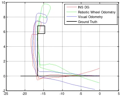
experimental trajectory is follow the red number, 1, as shown in Figure 5. The total length is about 50 meters, and the duration of experiment is about 8 minutes. After that, the experimental trajectory is extended to 60 meters, like the blue number 2 shown in Figure 5. In experiment 2, It is included the rapid U-turn. In Figure 6 and 7, there are four trajectories responding with different results. The red line is INS DG result, the green line is the result from robot mobile base and the blue line shows the visual odometry solution. The black line is the simulated ground truth for comparing each algorithms. As you can see from these two figures, the INS DG result is more close to ground truth. The robot solution is not fitted to ground truth. There are the orientation and scale problem in that. Furthermore, because of the misalignment between IMU and robot, the DG result is not matched with robotic wheel odometry. In the figure 7, DG solution is more stable and got the better performance. Sometimes, the visual solution can provide more stable heading information, but the scale and image quality are the important issues to figure out. As you can see from Figure 7, the Visual odometry solution has the heading problem when the robot makes the rapid U-turn. The results is in terms of the overlap and quality of image.
The table 2 shows the analysis of each algorithms. It is worth mentioning that the relative precision results of DG and Robotic wheel odometry are under the 2%. The Visual odometry relative precision is about 5%. Although the relative precision of robot is better than DG, there has the scale and heading problem of it. Comparing with
Figure 6. The comparison between indoor positioning solutions and ground truth in experiment 1
-25 -20 -15 -10 -5 0 5
Figure 7. The comparison between indoor positioning solutions and ground truth in experiment 2
Misclosure
Table 2. The misclosure and relative precision results.
4.2 Indoor Planar Map
In the second stage, the indoor MMS implemented in the indoor environment to extract the floor plan. There are two indoor floor plan from different sensor, Kinect and laser scanner. Both of plans are generated by same mobile base. The scan results shown in Figure 8, it is generated by the Kinect sensor. In Figure 9, the result is transfer into local level frame to display. As you can see from these pictures, it is not reasonable at the room. The shape of room is skew and has some problem in loop-closure. The Kinect sensor has the ability to provide 3D point clouds data, but sometimes the performance and stability is not good enough to finish the high accuracy survey.
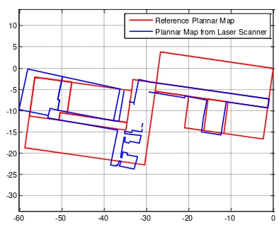
The second result is shown in Figure 10. Using the laser scanner, the accuracy of indoor map is better than the result from Kinect sensor. And the experiment area is extended to the other side of building. After the coordinate transformation, the planar maps is in the same coordinate system shown in Figure 12. The red map is the reference map generated from other
indoor MMS. In the right side of figure, the map is perfectly correspond to each other. However, there are some deformation and skew in the left side.
Figure 8. The floor plan from Kinect sensor
-10 -5 0 5 10 15 20 -15
-10
-5
0
5
Plannar Map from Kinect
Figure 9. The floor plan result from Kinect sensor shown in local level frame
Figure 10. The floor plan from laser scanner
-60 -50 -40 -30 -20 -10 -35
-30
-25
-20
-15
-10
-5
0
5
10
Plannar Map from Laser Scanner
Figure 11. The floor plan result from laser scanner shown in local level frame
-60 -50 -40 -30 -20 -10 0
-30 -25 -20 -15 -10 -5 0 5
10 Reference Plannar Map
Plannar Map from Laser Scanner
Figure 12. The comparison between reference map and floor plan result from laser scanner in local level frame
5. CONCULSION
This research proposes the architecture of equipment payload for indoor MMS. In first stage, the different positioning is implemented in indoor experiment. The performance of each algorithms can be seen in the comparison table. Even though the robotic wheel odometry is achieve the higher relative precision, there are the scale and heading problem to resolve. With the ground truth, the INS DG results is more matched with it. The misclosure of visual odometry is larger than others, but it is more stable when the duration of experiment is longer. In the future, it is necessary to combine each algorithm to get the better positioning results. In the indoor plan generated part, two kind of results are compared. The laser scanner has the better performance than Kinect sensor. However, the indoor MMS is also needed to the RGB-D sensor to provide the image and color point clouds to implement the 3D scene generated and visual odometry. Therefore, the indoor payload design included the laser scanner for planar map generated, Kinect sensor for visual odometry, 3D color point clouds and IMU sensor for the higher positioning performance.
ACKNOWLEDGEMENTS (OPTIONAL)
The author would acknowledge the financial supports provided by the Ministry of Science and Technology
(MOST-104-2923-M-006-001-MY3) and all technical assistances from his supervisor, Dr. Kai-Wei Chiang.
REFERENCES
Tao, V., Li, J., 2007. Advances in Mobile Mapping Technology, International Society for Photogrammetry and Remote Sensing (ISPRS) Book Series, Taylor and Francis Group: London, UK.
Karlsson N., Di Bernardo, E., Ostrowski J., Goncalves L., Pirjanian P., and Munich M. E., 2005. The vSLAM Algorithm for Robust Localization and Mapping. Robotics and Automation, 2005. ICRA 2005. Proceedings of the 2005 IEEE
International Conference on, pp. 24-29.
Litomisky, K., 2012. Consumer RGB-D Cameras and their Applications, University of California, Riverside.
Kohlbrecher, S., von Stryk, O., Meyer, J. and Klingauf, U., 2011. A flexible and scalable SLAM system with full 3D motion estimation, Safety, Security, and Rescue Robotics
(SSRR), 2011 IEEE International Symposium on, Kyoto, Japan,
pp. 155-160.
Okorn, B., Xiong, X., Akinci, B., and Huber, D., 2009. Toward automated modeling of floor plans. 3DPVT.
Turner, E. and Zakhor, A., 2014. Floor Plan Generation and Room Labeling of Indoor Environments from Laser Range Data.
GRAPP 2014, Lisbon, Portugal.
Grisetti, G., Stachniss, C., Burgard, W., 2007. Improved Techniques for Grid Mapping With Rao-Blackwellized Particle Filters. Robotics, IEEE Transactions on, vol. 23, no. 1, pp. 34-46.
Oliver, A., Kang, S., Wunsche, B. C., and MacDonald, B., 2012. Using the Kinect As a Navigation Sensor for Mobile Robotics.
In Proc. IVCNZ 2012 (2012), pp. 509-514.
Wang, F., Cui, J., Phang, S. K., Chen, B. and Lee, T., 2013. A Mono-Camera and Scanning Laser Range Finder Based UAV Indoor Navigation System. International Conference on
Unmanned Aircraft Systems, Atlanta, GA, pp. 694-701.
Morris, W., Dryanovski, I., Xiao, J., 2010. 3D indoor mapping for micro-UAVs using hybrid range finders and multi-volume occupancy grids. RSS 2010 workshop on RGB-D: Advanced
Reasoning with Depth Cameras, Zaragoza, Spain.
Bachrach, A., Prentice, S., He, R., Henry, P., Huang, A. S., Krainin, M., Maturana, D., Fox, D., and Roy, N., 2012. Estimation, planning and mapping for autonomous flight using an RGB-D camera in GPS-denied environments. International
Journal of Robotics Research, Vol 31, Issue 11, pp. 1320-1343.
Fallon, M. F., Johannsson, H., Brookshire, J., Teller, S. and Leonard, J. J., 2012. Sensor Fusion for Flexible Human-Portable Building-Scale Mapping. Intelligent Robots and
Systems (IROS), 2012 IEEE/RSJ International Conference on,
Vilamoura, pp. 4405-4412
Chong, K. and Kleeman, L., 1997. Accurate odometry and error modelling for a mobile robot. Robotics and Automation, 1997.
Proceedings. 1997 IEEE International Conference on, Vol 4,
pp. 2783-2788.
Lategahn, H., Geiger, A., Kitt, B., and Stiller, C., 2012. Motion-without structure: Real-time multi-pose optimization for accurate visual odometry. Intelligent Vehicles Symposium (IV),
2012 IEEE, pp. 649-654.