DEVELOPMENT OF A PEDESTRIAN INDOOR NAVIGATION SYSTEM BASED ON
MULTI-SENSOR FUSION AND FUZZY LOGIC ESTIMATION ALGORITHMS
Y. C. Lai a, *, C. C. Chang b, C. M. Tsai b, S. Y. Lin c, S. C. Huang b
a Dept. of Aerospace and Systems Engineering, Feng Chia University, Taiwan - [email protected]
b
Microsystem Technology Center, Industrial Technology Research Institute, Taiwan - (jinja, scart)@itri.org.tw
c
Cloud Service Technology Center, Industrial Technology Research Institute, Taiwan - [email protected]
Commission WG IV/7 and WG V/4
KEY WORDS: Dead Reckoning, Fuzzy Logic, Multi-Sensor Fusion, Inertial Measure Unit, Wearable Device, Portable Device
ABSTRACT:
This paper presents a pedestrian indoor navigation system based on the multi-sensor fusion and fuzzy logic estimation algorithms. The proposed navigation system is a self-contained dead reckoning navigation that means no other outside signal is demanded. In order to achieve the self-contained capability, a portable and wearable inertial measure unit (IMU) has been developed. Its adopted sensors are the low-cost inertial sensors, accelerometer and gyroscope, based on the micro electro-mechanical system (MEMS). There are two types of the IMU modules, handheld and waist-mounted. The low-cost MEMS sensors suffer from various errors due to the results of manufacturing imperfections and other effects. Therefore, a sensor calibration procedure based on the scalar calibration and the least squares methods has been induced in this study to improve the accuracy of the inertial sensors. With the calibrated data acquired from the inertial sensors, the step length and strength of the pedestrian are estimated by multi-sensor fusion and fuzzy logic estimation algorithms. The developed multi-sensor fusion algorithm provides the amount of the walking steps and the strength of each steps in real-time. Consequently, the estimated walking amount and strength per step are taken into the proposed fuzzy logic estimation algorithm to estimates the step lengths of the user. Since the walking length and direction are both the required information of the dead reckoning navigation, the walking direction is calculated by integrating the angular rate acquired by the gyroscope of the developed IMU module. Both the walking length and direction are calculated on the IMU module and transmit to a smartphone with Bluetooth to perform the dead reckoning navigation which is run on a self-developed APP. Due to the error accumulating of dead reckoning navigation, a particle filter and a pre-loaded map of indoor environment have been applied to the APP of the proposed navigation system to extend its usability. The experiment results of the proposed navigation system demonstrate good navigation performance in indoor environment with the accurate initial location and direction.
* Corresponding author. This is useful to know for communication with the appropriate person in cases with more than one author.
1. INTRODUCTION
With the enormous progress in electronic and communication technologies, portable or wearable devices have become popular and affordable nowadays, and they have become widely used in various applications, such as sport monitoring and management, healthcare, visitor navigation, etc. The Global Navigation Satellite Systems (GNSS) such as Global Position System (GPS) can provide accurate location information in open outdoor spaces, but they are not always available especially in GPS-denied environments such as indoors, undergrounds, and urban environments (Hemin et al., 2015).
To compensate the drawback of GNSS, some solutions, such as assisted GPS (A-GPS) and cellular-based positioning, but their accuracy is not enough to meet the demand of most indoor applications (Hui et al., 2007). Therefore, the development of indoor positioning systems, which are categorized into two types: device-free and device-based, has been a hot topic (Harle, 2013). Since the device-free type is still in its infancy and has a lot of limitations, the device-based becomes the main stream of indoor positioning (Youssef et al., 2007). Typical device-based location sensing methods include proximity(Hightower, 2004), triangulation (Harle, 2013), fingerprinting (Chintalapudi, et al., 2010), dead reckoning (Woodman and Harle, 2008), and so on.
Due to the progress in low-cost sensors based on micro electro-mechanical system (MEMS), Pedestrian Dead Reckoning (PDR) systems are becoming feasible options for indoor navigation and tracking. Low-cost sensors mean lower performance and high noisy compared with the expensive sensors. Therefore, the integration and combination of different sensors and algorithms are required to enhance the accuracy and usability of the PDR with low-cost sensors.
In this study, a sensor calibration procedure based on the scalar calibration and the least squares methods are induced in this study to improve the accuracy of the inertial sensors. With the calibrated inertial data, a PDR system based on multi-sensor fusion and fuzzy logic estimation algorithms is proposed. It is a self-contained dead reckoning navigation that means no other outside signal is demanded.
In order to achieve the self-contained capability, a portable and wear able inertial measure unit (IMU) were developed. The developed multi-sensor fusion algorithm provides the amount of the walking steps and the strength of each steps in real-time. Consequently, the estimated walking amount and strength per step are taken into the proposed fuzzy logic estimation algorithm to estimates the walking length of the user. Since the walking length and direction are both the required information of the dead reckoning navigation, the walking direction is
calculated by integrating the angular rate acquired by the gyroscope of the developed IMU module. Both the walking length and direction are calculated on the IMU module and transmit to a smartphone with Bluetooth to perform the dead reckoning navigation which is run on a self-developed APP.
2. HARDWARE DEVELOPMENT AND INERTIAL
SENSOR CALIBRATION
2.1 Wearable Inertial Sensor Module Development
The sensors of the proposed pedestrian navigation system are low-cost accelerometer and gyroscope that measure the signals from the inertial motion of the target objective. They are also termed inertial sensors. These low-cost sensors based on MEMS technology are commonly found in various applications such as human body motion tracking and flight control of a consumer drone. The inertial sensors transduce the inertial motion into analog or digital signals. In regard to acceleration motion, the accelerometer transfers the objective acceleration into physical value with unit in m/s2 or G. For the rotation motion, the gyroscope transfers the objection rotation into physical value with unit in deg/s. In this study, both the step length and moving direction are estimated from the outputs of the inertial sensors.
The features of MEMS sensors are their light weight and small size. However, the low-cost sensor implies lower performance compared to an expensive and highly accurate one. The major drawbacks of the low-cost sensors are large noise and measurement errors. This is the reason why the calibration and verification of the sensor module are critical and necessary procedures to enhance its accuracy and performance before its application (Lai et al., 2010). Therefore, in order to acquire the stable and reliable data, a low-cost and wearable sensor module has been developed in this study.
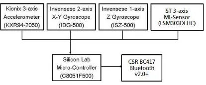
As shown in Figure 1, the developed module consists of one 3-axis accelerometer, one 2-3-axis X-Y gyroscope, one single-3-axis Z gyroscope, and one 3-axis e-compass. The applied 2-axis IDG-500 and single-axis ISZ-500 gyroscopes could be replaced by one 3-axis ITG-3050 gyroscope, and the adopted inertial sensors could also be updated to one 6-axis sensor containing a 3-axis gyroscope and a 3-axis accelerometer such as a MPU-6050 device, made by InvenSense, Inc. All the sensing data are collected and processed in a micro-controller, which is C8051F500 made by Silicon Labs. The estimated price of the adopted sensors and controller is under $20. In addition, a Bluetooth module was utilized to allow communication with other devices, such as smartphones or laptops, to execute the pedestrian navigation algorithm.
Figure 1. The block diagram of the developed inertial sensor
module
2.2 Sensor Error Model and Calibration Method
As mentioned above, the low-cost MEMS sensors suffer from high noise and errors which are the results of manufacturing imperfections and other side effects. Basically, these errors can be divided into two categories: random constant and time-correlated random process errors (Rogers 2003). Since the dynamical representation of random constant errors is simple and have a significant influence to the performance of the sensor, the selected calibration parameters are random constant errors which could result from scale factors, biases, and orthogonalization angles. The applied sensor error model of the specified sensor error triad is as follows:
b
T : orthogonalization angles matrix
Figure 2 shows the block diagram of the applied sensor error
Figure 2. Sensor error model of specified sensor triad
The sensor model is applied to different sensor triads, which are the accelerometer, gyroscope triads in this study. With the developed sensor module, the calibration procedures for each sensor triad can be accomplished by rotating the sensors to various random orientations or specified rotations. For each sensor triad, there are nine parameters, three scale factors, three biases and three nonorthogonal angles, to be determined, so that nine or more orientations and rotations are required to determine these parameters. The calibrations for each sensor triad are accomplished by using the scalar calibration and the least squares methods. More detail of the applied calibration methods can be referred to the study in (Lai et al, 2010).
2.3 Accelerometer Calibration
The calibration of the acceleration triad can be accomplished by using the magnitude of the Earth’s gravity field, which is constant in a specified location without the influence of other disturbances. Therefore, the reference value of the accelerometer triad is the gravitational constant represented by G. It is an empirical physical constant and independent of the
orientations of the sensor module when rested. For this reason, the exact orientation of the sensor triad is not required, but it is necessary to maintain static when acquiring the data.
The calibration of accelerometer triad was performed on a six-axis translation and rotation platform as shown in Figure 3. By fixing the sensor triad to at least nine different orientations on the platform and applying the least squares optimization, the nine parameter vector can be determined. The calibration results of the accelerometer triad are presented in Table 1. Figure 4 shows that the errors of the accelerometer triad lower 0.3% of the gravitational gravity G.
Figure 3. Six-axis translation and rotation platform
0 0.2 0.4 0.6 0.8 1 1.2 1.4 1.6 1.8
Figure 4. The calibration results of acceleration triad
Axis Scale factor Bias Nonorthogonal angle
x 0.9968 0.0506 -0.0207
y 0.9991 0.0006 0.0004
z 1.0025 0.0019 -0.0505
Table 1. Calibrated parameters of the accelerometer triad
2.4 Gyroscope Calibration
The calibration of the gyroscope triad also can be accomplished by applying the scalar calibration with a rotation platform. In this study, a single-axis rotation platform, as presented in Figure 5, was utilized to perform the calibration of the gyroscope triad. The platform can hold the sensor triad in desired orientations and perform the specified rotation with constant angular rate while the reference value of the rotating sensor triad can be determined. The specified angular rate was set to 300deg/sec during the calibration. Moreover, the accuracy biases of the gyroscope triad can be first determined by keeping the platform in static condition. After the biases are determined, the remaining unknown parameters are reduced to six, and it requires at least six different rotations of the platform with constant angular rate to apply the least squares optimization.
The result of the gyroscope calibration with this procedure is shown in Table 2. Figure 6 shows that the errors of the gyroscope triad with an error percentage lower than 0.2% of the reference angular rate.
Axis Scale factor Bias Nonorthogonal angle
x 1.0139 0.0506 -0.0050
y 0.9704 0.0021 0.0007
z 1.0025 0.0006 0.0054
Table 2. Calibrated parameters of the gyroscope triad
Figure 5. Single-axis Rotation Platform
Figure 6. The calibration results of the gyroscope triad
3. PEDESTRIAN NAVIGATION ALGORITHM
3.1 Pedestrian Navigation Scheme
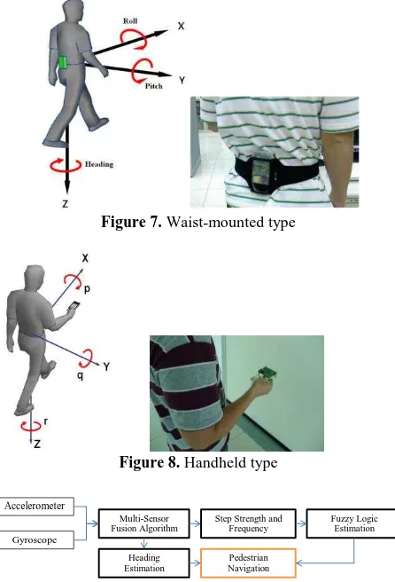
The developed wearable sensor module is designed to be waist-mounted or handheld as shown in Figure 7 and 8. With some preliminary tests, the waist-mount type was selected to implement the pedestrian navigation in this study, due to the higher accuracy and reliability than the handheld type. The waist-mounted type has the capability to describe the motion and action of lower limb more precise. In contrast, the handheld type is affected by how the user holds the device and the swinging motion of the hand while moving.
The proposed pedestrian navigation system is based on the step-and-heading-based dead reckoning and utilizes the multi-sensor fusion and fuzzy logic estimation algorithms. The scheme of this pedestrian navigation system is presented in Figure 9. The process of the multi-sensor fusion algorithm acquires the raw data from the sensor module to perform the sensor calibration and attitude estimation with a second order complementary
filter. It then outputs the estimated roll and pitch angles to the Step Strength and Frequency and the estimated heading angle to the Heading Estimation blocks. The Step Strength and Frequency block applies the roll angle, pitch angle, and the velocity in world x-axis, which is the integration of the acceleration in world x-axis, to calculate the step counting, step frequency, and step strength simultaneously. Figure 10 shows the roll angle, pitch angle, and the velocity in world x-axis, which are the forward/backward velocity and denoted as Vx. The red line in the top plot is moving detection index, and the values greater than zero are recorded to be moving period. The red asterisks in the bottom plot indicate the step counting results by utilizing the velocity in world x-axis to perform the step detection. Each asterisk in the plot represents a detected step.
Figure 7. Waist-mounted type
Figure 9. The scheme of the proposed pedestrian navigation
system
Figure 10. The roll angle, pitch angle, and the velocity in world
x-axis while walking
3.2 Multi-Sensor Fusion Algorithm
After completing the sensor calibration, the calibrated parameters of each sensor triad are implemented to the micro-controller to calibrate the data in real-time. Hence the performance and accuracy of the developed sensor module are improved. The direct outputs of the sensors are acceleration and angular rate of the target objective, but these signals are not enough to describe the motion of human body while walking. In order to extract more information of pedestrian activities, the multi-sensor fusion algorithm is one of the methods to achieve this goal. In this study, the multi-sensor fusion algorithm is used to derive the orientation information of the sensor module. The orientation is useful information to indicate the spatial condition of the target objective when performing various daily activities such as walking, jogging, cycling, etc. In this study, the Euler angles, namely roll, pitch and yaw angles, are adopted to be the orientation representation. Sometimes the yaw angle is termed the heading angle.
The roll and pitch angles are estimated by fusing the outputs of the accelerometer and gyroscopes with a second-order complementary filter (Aggarwal et al., 2006). The basic idea of the complementary filter is to fuse the roll and pitch angles derived from the gyroscope outputs through a high-pass filter and from the accelerometer through a low-pass filter to obtain the estimated attitude, thus compensating for the drift on the gyroscope and for the slow dynamics of the accelerometer. Consequently, the estimated attitudes would have both short-term and long-short-term accuracies.
Figure 11 presents the estimated roll and pitch angles from different methods when the subject is walking. The data denoted as “acc”, ‘’gyro”, and “CF” are the roll and pitch angles derived from the accelerometer, the gyroscope, and the complementary filter methods, respectively. The data reveal that the accelerometer suffers from high noise during high dynamic motion, the gyroscope suffers from drift problem, and only the complementary filter can perform well during both short-term and long-term.
Figure 11. The roll and pitch angles from different methods
3.3 Fuzzy Logic Estimation Algorithm
Fuzzy logic is applied to be the step length estimation of this study since it is a nonlinear and rule-based method, which means that no complex model is required, and it is comprised of linguistic rules, which implies that it can be easy realized by most computer programming languages. It has been applied to
many fields, from control theory to artificial intelligence. Basically, a fuzzy logic consists of three components, the fuzzifier, fuzzy inference engine and defuzzifier. The fuzzifier transforms a crisp input into some fuzzy sets, which are represented by membership functions. The fuzzy inference engine uses the fuzzy rules to reason for the fuzzy output. Then, the fuzzy output is transformed to crisp output by the defuzzifier.
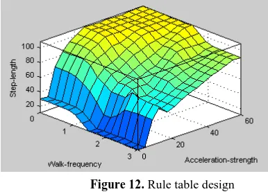
In this study, the adopted fuzzy rules are Mamdani-type (Tzafestas and Venetsanopoulos, 1994), also called max-min controllers, and the variables are two inputs and one output. The defuzzification strategy is the center of gravity method (Tzafestas and Venetsanopoulos, 1994). The input variables of the adopted fuzzy logic are step frequency and acceleration strength, and its output value is the estimated step length. The acceleration strength is calculated from the integration of resultant acceleration of every step. Figure 12 shows the design of the rule table in this study. Due to the difference of height, weight, and leg length between every subject, the design of the rule table varies with different individuals. For every subject, the fuzzy logic design needs to be adjusted from the testing data.
Figure 12. Rule table design
4. PEDESTRIAN NAVIGATION ALGORITHM
In order to verify the performance and accuracy of the proposed methods, an experiment was designed with a subject to walk in a straight line. The subject was asked to walk fifty steps naturally with different step lengths that are 30cm, 60cm, and 90cm. The walk direction and step lengths are referred to the arrangement and size of floor tiles, respectively. The applied multi-sensor fusion and fuzzy logic estimation algorithms were implemented to the MCU in real-time. The estimated walk heading and step length were transmitted to another device, such as a laptop or a smartphone, to perform pedestrian navigation. In this experiment, a laptop was applied to record the data and to monitor the execution of the system health. The experiment results are presented in Table 3. It shows that the accuracy of the step counting is up to 99% and the maximum error of the estimated step length is under 2cm.
Experiment
Step counting Estimated length(cm) Walking distance(m) detected Reference Mean Standard
Deviation Estimated reference
30cm 50 50 29.54 1.69 14.47 15.00
30cm 49 50 28.81 2.07 14.11 15.00
90cm 49 50 91.56 2.35 44.86 45.00
90cm 50 50 90.67 1.88 45.33 45.00
60cm 50 50 59.20 4.22 29.60 30.00
60cm 50 50 58.35 1.49 28.59 30.00
Total 298 300
Table 3. The experiment results of step length estimation
With the estimated heading and step lengths, the proposed methods were implemented on smartphone to perform pedestrian navigation in an exhibition hall. In this demonstration, the estimated heading and step lengths are transmitted to a smartphone with Bluetooth. This smartphone has the capability to run a self-developed APP with the map matching and particle filter algorithms. A subject wore the developed IMU module and held the smartphone. After setting the initial location and direction, the subject walked into this exhibition hall and return to the exit as shown in Figure 13. The result shows that the subject is able to return to the same exit with the help of the proposed pedestrian navigation system.
Figure 13. Demonstration of the proposed pedestrian
navigation in an exhibition hall
5. CONCLUSION
A pedestrian indoor navigation system based on the multi-sensor fusion and fuzzy logic estimation algorithms has been successfully developed in this study. The proposed pedestrian navigation system is based on the step-and-heading-based dead reckoning. It applied a self-developed portable and wearable inertial measure unit (IMU). Its adopted sensors are the low-cost inertial sensors, accelerometer and gyroscope, based on the micro electro-mechanical system (MEMS). There are two types of the developed IMU modules, handheld and waist-mounted. Since the low-cost MEMS sensors suffer from various errors, a sensor calibration procedure based on the scalar calibration and the least squares methods has been induced in this study to improve the accuracy of the inertial sensors.
With the calibrated data acquired from the inertial sensors, the step length and strength of the pedestrian are estimated by multi-sensor fusion and fuzzy logic estimation algorithms. The developed multi-sensor fusion algorithm provides the amount of the walking steps and the strength of each steps in real-time. The experiment results show that the accuracy of the step counting is up to 99% and the maximum error of the estimated step length is under 2cm. Due to the error accumulating of dead reckoning navigation, a particle filter and a pre-loaded map of indoor environment have been applied to a self-developed APP to demonstrate the proposed navigation system. This experiment result demonstrated good navigation performance of the proposed system in indoor environment with the accurate initial location and direction.
ACKNOWLEDGEMENTS
This study was supported in part by the Ministry of Science and Technology of Taiwan under grant number MOST 103 - 2221 - E - 035 - 067.
REFERENCES
Aggarwal, Priyanka, Zainab Syed, Xiaoji Niu, and Naser El-Sheimy. 2006. Cost-effective testing and calibration of low cost MEMS sensors for integrated positioning, navigation and mapping systems. Proceedings of XIII FIG Conference.
Chintalapudi, Krishna, Anand Padmanabha Iyer, and Venkata N Padmanabhan. 2010. Indoor localization without the pain. Proceedings of the sixteenth annual international conference on Mobile computing and networking.
Harle, R. 2013. A Survey of Indoor Inertial Positioning Systems for Pedestrians. Communications Surveys & Tutorials, IEEE 15 (3):1281-1293.
Hemin, Zhang, Yuan Weizheng, Shen Qiang, Li Tai, and Chang Honglong. 2015. A Handheld Inertial Pedestrian Navigation System With Accurate Step Modes and Device Poses Recognition. Sensors Journal, IEEE 15 (3):1421-1429. doi: 10.1109/JSEN.2014.2363157.
Hightower, Jeffrey. 2004. The location stack. PhD Dissertation Citeseer.
Hui, Liu, H. Darabi, P. Banerjee, and Liu Jing. 2007. Survey of Wireless Indoor Positioning Techniques and Systems. Systems, Man, and Cybernetics, Part C: Applications and Reviews, IEEE Transactions on 37 (6):1067-1080.
Lai, Ying-Chih; Jan, Shau-Shiun; Hsiao, Fei-Bin. 2010. Development of a Low-Cost Attitude and Heading Reference System Using a Three-Axis Rotating Platform. Sensors 10, no. 4: 2472-2491.
Rogers, Robert M. 2003. Applied mathematics in integrated navigation systems. Vol. 1: Aiaa.
Tzafestas S.G., Venetsanopoulos A.N., 1994, Fuzzy reasoning in information, decision, and control systems, Kluwer Academic, Dordrecht ; Boston.
Woodman, Oliver, and Robert Harle. 2008. Pedestrian localisation for indoor environments. Proceedings of the 10th international conference on Ubiquitous computing, Seoul, Korea.
Youssef, Moustafa, Matthew Mah, and Ashok Agrawala. 2007. Challenges: device-free passive localization for wireless environments. Proceedings of the 13th annual ACM international conference on Mobile computing and networking, Canada.