AutoCAD
2009 &
AutoCAD LT
®
2009 Bible
AutoCAD
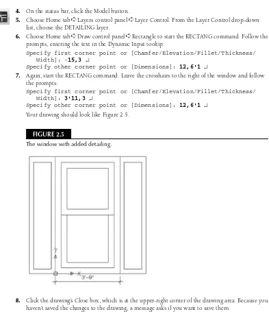
2009 &
AutoCAD LT
®
2009 Bible
111 River Street Hoboken, N.J. 07030 www.wiley.com
Copyright © 2008 by Wiley Publishing, Inc., Indianapolis, Indiana Published by Wiley Publishing, Inc., Indianapolis, Indiana Published simultaneously in Canada
ISBN: 978-0-470-26017-3
Manufactured in the United States of America 10 9 8 7 6 5 4 3 2 1
No part of this publication may be reproduced, stored in a retrieval system or transmitted in any form or by any means, electronic, mechanical, photocopying, recording, scanning or otherwise, except as permitted under Sections 107 or 108 of the 1976 United States Copyright Act, without either the prior written permission of the Publisher, or authorization through payment of the appropriate per-copy fee to the Copyright Clearance Center, 222 Rosewood Drive, Danvers, MA 01923, (978) 750-8400, fax (978) 646-8600. Requests to the Publisher for permission should be addressed to the Legal Department, Wiley Publishing, Inc., 10475 Crosspoint Blvd., Indianapolis, IN 46256, (317) 572-3447, fax (317) 572-4355, or online at http://www.wiley.com/go/permissions.
No part of this publication may be reproduced, stored in a retrieval system or transmitted in any form or by any means, electronic, mechanical, photocopying, recording, scanning or otherwise, except as permitted under Sections 107 or 108 of the 1976 United States Copyright Act, without either the prior written permission of the Publisher, or authorization through payment of the appropriate per-copy fee to the Copyright Clearance Center, 222 Rosewood Drive, Danvers, MA 01923, (978) 750-8400, fax (978) 646-8600. Requests to the Publisher for permission should be addressed to the Legal Department, Wiley Publishing, Inc., 10475 Crosspoint Blvd., Indianapolis, IN 46256, (317) 572-3447, fax (317) 572-4355, or online at http://www.wiley.com/go/permissions.
LIMIT OF LIABILITY/DISCLAIMER OF WARRANTY: THE PUBLISHER AND THE AUTHOR MAKE NO REPRESENTATIONS OR WARRANTIES WITH RESPECT TO THE ACCURACY OR COMPLETENESS OF THE CONTENTS OF THIS WORK AND SPECIFICALLY DISCLAIM ALL WARRANTIES, INCLUDING WITHOUT LIMITATION WARRANTIES OF FITNESS FOR A PARTICULAR PURPOSE. NO WARRANTY MAY BE CREATED OR EXTENDED BY SALES OR PROMOTIONAL MATERIALS. THE ADVICE AND STRATEGIES CONTAINED HEREIN MAY NOT BE SUITABLE FOR EVERY SITUATION. THIS WORK IS SOLD WITH THE UNDERSTANDING THAT THE PUBLISHER IS NOT ENGAGED IN RENDERING LEGAL, ACCOUNTING, OR OTHER PROFESSIONAL SERVICES. IF PROFESSIONAL ASSISTANCE IS REQUIRED, THE SERVICES OF A COMPETENT PROFESSIONAL PERSON SHOULD BE SOUGHT. NEITHER THE PUBLISHER NOR THE AUTHOR SHALL BE LIABLE FOR DAMAGES ARISING HERE FROM. THE FACT THAT AN ORGANIZATION OR WEBSITE IS REFERRED TO IN THIS WORK AS A CITATION AND/OR A POTENTIAL SOURCE OF FURTHER INFORMATION DOES NOT MEAN THAT THE AUTHOR OR THE PUBLISHER ENDORSES THE INFORMATION THE ORGANIZATION OR WEBSITE MAY PROVIDE OR RECOMMENDATIONS IT MAY MAKE. FURTHER, READERS SHOULD BE AWARE THAT INTERNET WEBSITES LISTED IN THIS WORK MAY HAVE CHANGED OR DISAPPEARED BETWEEN WHEN THIS WORK WAS WRITTEN AND WHEN IT IS READ.
For general information on our other products and services or to obtain technical support, please contact our Customer Care Department within the U.S. at (800) 762-2974, outside the U.S. at (317) 572-3993 or fax (317) 572-4002. Library of Congress Control Number is available from the publisher upon request.
Trademarks:Wiley, the Wiley logo, and related trade dress are trademarks or registered trademarks of John Wiley & Sons, Inc. and/or its affiliates, in the United States and other countries, and may not be used without written permission.
Autodesk, AutoCAD, AutoCAD LT and DWF are either registered trademarks or trademarks of Autodesk, Inc., in the U.S.A. and/or certain other countries. Certain content, including trial software, provided courtesy Autodesk, Inc, (c)2008. All other trademarks are the property of their respective owners. Wiley Publishing, Inc. is not associated with any product or vendor mentioned in this book.
Ellen Finkelstein learned AutoCAD in Israel, where she always got to pore over the manual because it was in English. After returning to the United States, she started consulting and teaching AutoCAD as well as other computer programs, including Microsoft Word, Excel, and PowerPoint. She has also taught courses on Web writing and usability. Her Web site, www.ellenfinkelstein.com, contains tips and techniques for AutoCAD and PowerPoint, and she publishes a monthly AutoCAD Tips Newsletter. Ellen has written extensively on AutoCAD, including articles for Autodesk’s Web site, such as three white papers on dynamic blocks, and features for AutoCAD’s Help system. She is also the editor of Inside AutoCAD, a monthly newsletter published by Eli Journals.
Ellen’s first book was AutoCAD For Dummies Quick Reference. Since then, she has written books on
Credits
Acquisitions Editor Stephanie McComb
Project Editor Jade L. Williams
Technical Editor Lee Ambrosius
Copy Editor Marylouise Wiack
Editorial Manager Robyn Siesky
Business Manager Amy Knies
Vice President & Executive Group Publisher Richard Swadley
Vice President and Executive Publisher Bob Ipsen
Vice President and Publisher Barry Pruett
Project Coordinator Katherine Key
Graphics and Production Specialists Claudia Bell
Reuben W. Davis Heather Pope Ronald Terry
Quality Control Technician Melanie Hoffman
Media Development Specialist Angela Denny
Proofreading and Indexing Laura L. Bowman
C
Whether you are a new or expert user with AutoCAD, you have truly made a worthwhile investment with the AutoCAD Bible. This book will be a valuable addition to your library that you will use on a reg-ular basis as a reference and guide to using AutoCAD. With each release of AutoCAD and its new feature set, the AutoCAD Bible is an excellent resource for learning and getting up to speed quickly on all things AutoCAD.
Everything from the basics of AutoCAD including 3D and programming is covered in this book. The information is well organized and a comprehensive index makes retrieving information that you need a cinch.
You’ll see real-world examples and AutoCAD drawings on the DVD that will quickly help you under-stand and learn new concepts through the exercises. Even more helpful is the fact that the drawings are available in both a before and after format, allowing you to use the after format as a reference.
Ellen has been writing books about AutoCAD for so long that she is practically a household name here at Autodesk and in the AutoCAD world. She is an active participant in our beta program and helps shape the direction of future releases of AutoCAD. You are truly learning from one of the finest and experienced professionals in this field.
Although the in-depth coverage of this book may seem overwhelming, do not feel discouraged by the books thickness. Pick out the tools that you want to learn about and then proceed from there, or if you are interested in learning new features, pick a different topic each week to learn about.
Thank you, Ellen, for creating another great edition of the AutoCAD Bible. I know our customers will benefit from reading it as I have.
W
guide to both the AutoCAD and AutoCAD LT programs.
This book covers every significant AutoCAD and AutoCAD LT feature. If you’re a beginning user, you’ll find everything you need to start out; if you’re already using AutoCAD or AutoCAD LT regularly, the book covers advanced material, as well. Although you can use this book as a tutorial if you’re just start-ing out or learnstart-ing a new set of features, it also provides a solid reference base to come back to again and again. The short tutorials on almost every topic will quickly have you creating professional-level draw-ings. The DVD is chock-full of drawings, a trial version of AutoCAD 2009, and add-in programs (which are mostly for AutoCAD only). This book is all that you need to make full use of either program.
For AutoCAD 2009, the emphasis is on a new interface, quick access to information, navigation, and a new macro recorder. Most of the new features are in AutoCAD LT 2009, as well.
Is This Book for You?
The AutoCAD 2009 & AutoCAD LT 2009 Biblecovers all of the essential features of AutoCAD and AutoCAD LT and includes clear, real-life examples and tutorials that you can adapt to your needs.
Although I fully cover the basics, I have also included material on the many advanced features, such as external database connectivity, AutoLISP, Visual Basic for Applications (VBA), 3D modeling, rendering, and customization. (Most of the advanced features apply to AutoCAD only.) The following categories should help you decide whether this book is for you.
If you are a new AutoCAD or AutoCAD LT user
If you are new to AutoCAD or AutoCAD LT, the AutoCAD 2009 & AutoCAD LT 2009 Bibleguides you through all that you need to know to start drawing effectively, whatever your field. Just start at the beginning.
If you are switching from another CAD program
You already know what CAD is all about. This book clearly explains the AutoCAD and AutoCAD LT way of drawing the models that you have already been drawing. In addition, you’ll find a great deal of essential information about transferring files and data from other formats.
How This Book Is Organized
This book is divided into eight parts.
Part I: AutoCAD and AutoCAD LT Basics
Part I provides the background information that you need to start drawing. It starts with a “quick tour” that has you drawing right away, and then covers how to start a drawing, use commands, specify coordinates, and set up a drawing.
Part II: Drawing in Two Dimensions
Part II covers all of the commands and procedures for drawing and editing in two dimensions. In addition, I discuss how to control the drawing process with layers, zooming, and panning. Also included in this part is information about dimensioning, plotting, and printing.
Part III: Working with Data
Part III covers many ways to organize and share data, including blocks, attributes, external references, and external databases.
Part IV: Drawing in Three Dimensions
Part IV explains everything that you need to know to draw in three dimensions. It also discusses how to present 3D drawings using hiding, shading, and rendering techniques.
Part V: Organizing and Managing Drawings
Part V helps you to incorporate AutoCAD and AutoCAD LT into your work world by explaining how to set standards, manage drawings, and work with other applications. It concludes with a chapter on creating electronic output.
Part VI: Customizing AutoCAD and AutoCAD LT
Part VI introduces the tools that you need to customize commands, toolbars, linetypes, hatch patterns, shapes, fonts, and the ribbon. You’ll also find a chapter on creating macros with script files as well as the Action Recorder.
Part VII: Programming AutoCAD
Part VIII: Appendixes
Part VIII provides additional information for AutoCAD and AutoCAD LT users. Appendix A gives instruc-tions for installing and configuring AutoCAD and AutoCAD LT. Appendix B covers additional resources for AutoCAD and AutoCAD LT users. Appendix C explains what you’ll find on the DVD.
The DVD contains a complete copy of this book in nonprintable PDF format.
How to Use This Book
You can use this book in two ways: as a tutorial and learning tool, or as a reference.
As a tutorial
The overall organization of the book goes from simple to complex, and each chapter has several step-by-step exercises. This enables you to use the book as a tutorial, from beginning to end. You can always go back and redo any exercise when you need to refresh your memory on a particular feature.
For newcomers to AutoCAD or AutoCAD LT, Parts I (AutoCAD and AutoCAD LT Basics) and II (Drawing in Two Dimensions) are essential. After that, you can refer to chapters that interest you. Parts III (Working with Data) and V (Organizing and Managing Drawings) are also useful for beginners. Intermediate users will probably be familiar with most of the material in Part I and will be more likely to skip around, looking for the specific topics that they need. However, don’t forget that many new features are introduced in Part I. Enough material appears in this book to bring intermediate users up to a fairly advanced level.
I have designed this book to be comprehensive and to include every significant feature of AutoCAD and AutoCAD LT. Therefore, do not be concerned if some of the material seems too advanced. It will be there when you are ready for it.
As a reference
The AutoCAD 2009 & AutoCAD LT 2009 Bibleis organized as a reference that you can refer to whenever you are stuck, or when you try to do something for the first time. Each chapter covers a topic completely, mak-ing it easy to find what you’re lookmak-ing for. Each Steps exercise (with a few exceptions) can be done on its own without doing the other exercises in the chapter. You can easily look up a topic and complete a related exercise without having to go through the entire chapter. A complete index at the back of the book can also help you to find features and topics.
Doing the Exercises
In addition, as you work through some of the exercises in this book, you will make certain changes in the program’s setup. Most of these are minor changes that any user would make while drawing. For safety, Cautions and Tips accompany all changes that could have serious consequences, such as customizing the menu. For example, when customizing the menu, you will be instructed to copy the menu file under a new name, and you will then work with the new menu file, not the original one. Nevertheless, if you are work-ing on a network or sharwork-ing your computer with someone else, it is important to consult with others who may be affected by the changes that you make.
If you do the exercises, I recommend that you do them from the beginning. Important instructions are given during earlier exercises that may affect your system later. For example, one of the first exercises is to create a new folder to hold your drawings from the exercises. This folder keeps your exercise drawings sep-arate from other drawings that have been created in your office. However, each exercise stands on its own so that you can go back and do only the exercise that you need.
You can create your own configuration to help ensure that some changes that you make will not affect others. Instructions for doing this appear in Appendix A under the heading “Creating Multiple Configurations.”
The exercises in the AutoCAD 2009 & AutoCAD LT 2009 Biblehave been carefully checked by a technical editor to ensure accuracy. However, we cannot anticipate all situations, due to either varying hardware and software configurations or customization. If you have a problem with an exercise, contact me at the e-mail address listed at the end of this Preface so that I can correct the problem in the book’s next edition. I will also try to give you the information that you need to complete the exercise.
Conventions Used in This Book
Given all the ways in which you can execute a command in AutoCAD and AutoCAD LT, you’ll find it useful to read this section, which describes this book’s typographical conventions. You will find this section helpful for doing the step-by-step exercises as well.
Using commands
AutoCAD and AutoCAD LT offer workspaces (covered fully in Appendix A) that provide very different ways of executing commands. The default workspace, 2D Drafting & Annotation, uses the ribbon and menu browser, whereas the Classic workspace uses more traditional menus and toolbars. I use this default workspace (or the 3D Modeling workspace for 3D drawing in AutoCAD) throughout the book. All workspaces offer a command line, where you can execute a command by entering its name.
When I explain how to execute a command, I give the instructions for doing so on the ribbon, if possible. In addition, I almost always provide the name of the command so that you can enter it on the command line.
The new ribbon created a quandary for me, because I know that some people, especially those upgrading from earlier releases, will not use it; instead, they will prefer to use the Classic workspace with its familiar menus and toolbars. However, I felt that explaining how to execute each command in three ways (the rib-bon, the menu/toolbar, and on the command line) would be awkward, perhaps confusing, and space-consuming. What should you do if you are using this book with the Classic workspace?
CRO
SS
-REF
In many cases, especially if you’re upgrading, you’ll already know where to find familiar commands. For new commands, it’s easy to find their location in the Classic workspace by going to the Help system. Follow these steps:
1. Press F1 to open the Help window.
2. Click the Contents tab on the left.
3. Expand the Command Reference and then the Commands item.
4. Expand the listing of the command’s first letter and click the command.
5. Look at the top of the right-hand pane, where you’ll find instructions for all the available methods of executing the command.
When referring to the ribbon, I might say, “Choose Home tab➪Draw panel➪Line,” which means to click the Home tab if it’s not already displayed, look for the Draw control panel, and click the Line button in that panel. If you’re not sure which button to click, hover the mouse cursor over a button to see its tooltip, which provides more information. You can expand many control panels by clicking their title at the bottom of the ribbon; if a command is on the expanded section, I indicate that in the instruction.
A few of the ribbon control panels have drop-down lists (or flyouts), which are equivalent to sub-menus. Therefore, to indicate which button to choose, I may need to tell you to choose Home tab➪Utilities panel ➪Zoom drop-down list➪ Zoom Extents. Although I haven’t found a good alternative, this is not com-pletely satisfactory for two reasons. First, it’s a mouthful! Second, the flyout names do not appear, making it hard to know which is the Zoom drop-down list. However, in most cases, the button icon will make it obvi-ous which drop-down list I’m talking about.
To indicate that you should choose a command from the menu, for example, I say, “Choose Menu Browser➪View➪Viewports,” which means that you should click the Menu Browser button at the upper-left corner of the application window, then click the View menu, and finally click the Viewports menu item.
Every command also has a command name that you can type on the command line, which appears at the bottom of your screen. Command names are shown in capital letters, as in CIRCLE. AutoLISP functions (which apply to AutoCAD only) are shown in small capital letters, as in COMMAND.
Figures
In order to create clear, legible figures, I have used a white background in AutoCAD and AutoCAD LT. However, many people use a black drawing area. In Appendix A, I explain how to change this color. As you read through the book, you should be aware that you may see on your screen a negative image of what I show in the figures — a dark background and light-colored objects. Once you get used to this difference, you’ll easily recognize what you see in the figures.
In AutoCAD, the 3D environment further changes what you see on your screen. The default 3D background is gray. Again, I have sometimes changed the background color to white for the purpose of creating a clear figure.
Prompts, your input, and instructions
The Dynamic Input feature shows prompts near your cursor, but additional options only appear if you click the down arrow on your keyboard. To make clear all of the available options, I use the command line for-mat of prompts.
Here’s a sample step-by-step section. In this exercise, you click the proper ribbon button (which is shown in the margin), type the number shown in bold, press Enter where indicated by the bent arrow (↵) symbol, and follow the instructions that appear in italic.
8. To create a second rectangle inside the first one, choose the Home tab➪Modify panel➪Offset. (I cover this and other editing commands in Chapters 9 and 10.) Follow these prompts:
Specify offset distance or [Through/Erase/Layer] <Through>: 4 ↵
Select object to offset or [Exit/Undo] <Exit>: Click the rectangle to select it.
Specify point on side to offset or Exit/Multiple/Undo] <Exit>: Click anywhere inside the rectangle.
Select object to offset or [Exit/Undo] <Exit>: ↵
Often I refer to specific elements in a drawing. References to these elements appear in the text as numbers in circles, such as 1, 2, 3, and so on. You’ll find the corresponding number in the figure to which the text refers.
Mouse and keyboard terms
You can draw using a mouse or a puck. The mouse is familiar to all users. A puck (or sometimes a stylus) is used with a digitizing tablet. Because most users do not have a digitizing tablet, I do not directly refer to it in this book. If you have one, follow the instructions for using the mouse in the same way, but using your puck.
A mouse can have two or more buttons. Many users like using a mouse with at least three buttons because you can customize the buttons to suit your needs. However, because many mice have only two buttons, I assume only two. The left mouse button is used to choose commands and toolbar buttons, and to pick points in your drawing. For this reason, it is sometimes called the pick button. The right button usually opens a shortcut menu.
The time-sensitive right-clicking feature enables you to use the right button either to open a shortcut menu or as the equivalent of pressing Enter. Because this feature is not on by default, I do not assume that you have turned it on. I use the term right-clickwhen you need to access a shortcut menu. If you have time-sensitive right-clicking turned on, you need to hold down the right mouse button more than 250 milli-seconds (by default) to display the shortcut menu. See Chapter 3 and Appendix A for more details.
If I say one of the following
Choose Menu Browser➪Tools➪Options
Choose Home tab➪Draw control panel➪Line
Select the circle in your drawing
it means that you need to use the left button of your mouse.
I also use the mouse terms listed in the following table.
Mouse Terms
Term Description
Cursor The shape on your screen that shows you where the mouse is pointed. It can take a number of shapes, such as crosshairs, pickbox, or arrow. It is also known as the mouse pointer.
Pickbox A type of cursor consisting of a small box, used to select drawing objects.
Crosshairs A type of cursor consisting of intersecting lines, sometimes with a pickbox at their center. Pick Point to a drawing object and click the left mouse button.
Click Press the left mouse button once and release it. Double-click Press the left mouse button twice in rapid succession.
Click and drag Click the left mouse button and hold it down while you move the mouse, dragging an object on your screen with it.
Choose Click a ribbon item, menu item, toolbar button, or dialog box item. You can sometimes choose an item using the keyboard, as well. I also use this word when you need to choose a command option, which you can do by choosing from a shortcut menu with a mouse, but also by typing the option’s abbreviation on the keyboard.
Right-click Press the right mouse button once and release it. If you have turned on time-sensitive right-clicking, hold the right mouse button at least 250 milliseconds (by default) before releasing it. Shift and click While holding down the Shift key, press the left mouse button once and release it.
Shift and right-click While holding down the Shift key, press the right mouse button once and release it. Shift and mouse wheel A new shortcut in AutoCAD for temporarily starting the 3DORBIT command requires you to
press the Shift key and hold down the mouse wheel, using it like a button.
Select Highlight an object in a drawing by picking it or by using another object selection method, or highlight text in a dialog box or text document.
What the Icons Mean
AutoCAD 2009 & AutoCAD LT 2009 Bibleis liberally sprinkled with icons — symbols in the left margin that call your attention to noteworthy points.
This icon means that the feature that I am discussing is not available in AutoCAD LT.
The Caution icon means that you should pay special attention to the information or instruc-tions because a possibility exists that you could cause a problem otherwise.
Cross-References refer you to a related topic elsewhere in the book. Because you may not read this book straight through from cover to cover, you can use cross-references to quickly find just the information you need.
CRO
SS
-REF
CRO
SS
-REF
CAUTION
CAUTION
AUTOCAD ONLY
The New Feature icon means that a feature is new to AutoCAD 2009 or AutoCAD LT 2009 or has been significantly changed.
A Note icon alerts you to some important point that requires special attention, or additional information that may be helpful.
The On the DVD icon highlights references to related material on the DVD.
A Tip shows you a way to accomplish a task more efficiently or quickly. You’ll find plenty of practical advice here.
About the DVD
The DVD contains all of the drawings that you need to do the exercises in this book. These drawings are a great resource to help you learn using real-world drawings. In addition, the DVD includes the drawings that result after you finish an exercise or tutorial. In this way, you can check whether you have done an exercise correctly.
The DVD also contains many add-on programs that I hope you will find useful. I am especially pleased to include 30-day trial versions of AutoCAD 2009 and AutoCAD LT 2009 on the DVD, as well as this entire book in (nonprintable) PDF format.
Other Information
If you are already an advanced user but need tips and secrets for getting the most out of AutoCAD or AutoCAD LT, this book will probably not add too much to your already great store of knowledge. However, few people know everything about these complex programs, and so you may be surprised by what you can learn.
This book assumes that you know the basics of Windows, although the instructions that you’ll read here are usually detailed enough to get you through any task.
AutoCAD 2009 & AutoCAD LT 2009 Biblecovers AutoCAD 2009 and AutoCAD LT 2009. However, most of the information also applies to the 2008 release of both programs. I have used AutoCAD in Windows Vista, but almost everything also applies to Windows XP, although some of the screens will look different. If you are using AutoCAD LT 2009, again, some of the screens will look different. Where there is a significant dif-ference between AutoCAD and AutoCAD LT, I explain the difdif-ference.
Contacting the Author
I would be happy to hear any comments that you have about this book. The best way to contact me is by e-mail at [email protected]. You can also use the United States Postal Service (a.k.a. snail mail) and write to me in care of Wiley. Please note that I can’t provide technical support for my readers. The publisher maintains a page on its site that includes the drawings used in the exercises (in case you lose your DVD) and any errata at www.wiley.com/go/autocad2009bible. I have my own Web site at
www.ellenfinkelstein.comthat contains information on my books and on AutoCAD, including many AutoCAD tips. I invite you to sign up there for my free AutoCAD Tips Newsletter, so that you can continue the learning process.
TIP
TIP
NOTE
NOTE
NEW FEATURE
I
A huge thank-you goes to Jade Williams, whose infinite organizing power kept the book on track. Jade kept up with a seemingly infinite number of versions of text documents and images, coordinating the writing, editing, and production of the entire book. I don’t know how this book could exist without her.
My thanks to Lee Ambrosius, an AutoCAD consultant (www.hyperpics.com), and the highly knowl-edgeable technical editor for the book. Lee’s comments improved the book throughout.
I also thank Marylouise Wiack for her precise editing of this very technical book, and all of the people at Wiley who helped with the production of this book and its DVD.
Thanks to Doug Cochran, the AutoCAD Product Manager at Autodesk, Inc., for writing a great Foreword for this book. I also want to express my great appreciation to the members of Autodesk’s beta and product teams who were very supportive throughout the alpha and beta period. They include: Shaan (the great) Hurley, Nate Bartley, Alex Bicalho, Matt Stein, Eric Stover, and many others.
Many people contributed drawings and software for this book. I’d like to thank all of them. They have helped to make this book the most comprehensive book on AutoCAD and AutoCAD LT available. I specifically want to thank Lee Ambrosius and Melanie Perry for their help in updating several of the chapters in this book. This book is long and detailed, and their able assistance made it possible for me to meet my deadlines.
Part I: AutoCAD and AutoCAD LT Basics . . . 1
Quick Start: Drawing a Window...3
Chapter 1: Starting to Draw ...13
Chapter 2: Opening a Drawing ...27
Chapter 3: Using Commands ...37
Chapter 4: Specifying Coordinates ...61
Chapter 5: Setting Up a Drawing ...95
Part II: Drawing in Two Dimensions . . . 111
Chapter 6: Drawing Simple Lines ...113
Chapter 7: Drawing Curves and Points...121
Chapter 8: Viewing Your Drawing ...137
Chapter 9: Editing Your Drawing with Basic Tools ...171
Chapter 10: Editing Your Drawing with Advanced Tools ...195
Chapter 11: Organizing Drawings with Layers, Colors, Linetypes, and Lineweights ...253
Chapter 12: Obtaining Information from Your Drawing ...287
Chapter 13: Creating Text...309
Chapter 14: Drawing Dimensions...361
Chapter 15: Creating Dimension Styles ...409
Chapter 16: Drawing Complex Objects ...441
Chapter 17: Plotting and Printing Your Drawing...483
Part III: Working with Data . . . 519
Chapter 18: Working with Blocks and Attributes ...521
Chapter 19: Referencing Other Drawings ...585
Chapter 20: Working with External Databases ...609
Part IV: Drawing in Three Dimensions . . . 639
Chapter 21: Specifying 3D Coordinates ...641
Chapter 22: Viewing 3D Drawings ...667
Chapter 23: Creating 3D Surfaces...713
Chapter 24: Creating Solids and Editing in 3D ...753
Chapter 27: Working with Other Applications ...911
Chapter 28: Creating Electronic Output ...935
Part VI: Customizing AutoCAD and AutoCAD LT . . . 959
Chapter 29: Customizing Commands, Toolbars, and Tool Palettes ...961
Chapter 30: Creating Macros and Slide Shows ...983
Chapter 31: Creating Your Own Linetypes and Hatch Patterns ...997
Chapter 32: Creating Shapes and Fonts ...1009
Chapter 33: Customizing the Ribbon and Menus ...1021
Part VII: Programming AutoCAD. . . 1047
Chapter 34: Understanding AutoLISP and Visual LISP Basics ...1049
Chapter 35: Exploring AutoLISP Further ...1065
Chapter 36: Exploring Advanced AutoLISP Topics ...1091
Chapter 37: Programming with Visual Basic for Applications ...1107
Part VIII: Appendixes . . . 1137
Appendix A: Installing and Configuring AutoCAD and AutoCAD LT ...1139
Appendix B: AutoCAD and AutoCAD LT Resources ...1167
Appendix C: What’s on the DVD-ROM...1173
Acknowledgments . . . xv
Part I: AutoCAD and AutoCAD LT Basics
1
Quick Start: Drawing a Window . . . 3
Summary ...12
Chapter 1: Starting to Draw . . . 13
AutoCAD’s Advantages ...13
Comparing AutoCAD and AutoCAD LT ...14
Starting AutoCAD and AutoCAD LT...15
Creating a New Drawing ...15
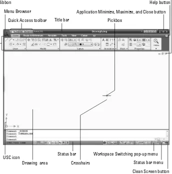
Using the AutoCAD and AutoCAD LT Interface ...15
The drawing area ...16
The UCS icon ...17
The crosshairs ...18
The ribbon and Quick Access toolbar ...18
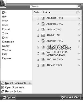
Using the Menu Browser ...19
The command line and dynamic input tooltip ...20
The status bar ...20
Creating a New Folder ...20
Using the Interface ...21
Saving a Drawing ...23
Closing a Drawing and Exiting from AutoCAD and AutoCAD LT ...25
Summary ...26
Chapter 2: Opening a Drawing . . . 27
Creating a New Drawing from a Template ...27
Working with Templates...29
Customizing the default template...29
Creating your own templates ...30
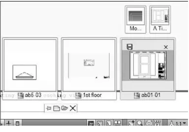
Opening an Existing Drawing...31 Using other ways to open drawings ...32 Switching among open drawings ...32 Using an Existing Drawing as a Prototype ...33 Saving a Drawing under a New Name ...33 Summary ...35
Chapter 3: Using Commands . . . 37
The AutoCAD and AutoCAD LT Interface ...37 Using the ribbon ...37 The Command Line and Dynamic Input ...43 Using Dynamic Input...43 Using one command within another command ...51 Of Mice and Pucks ...53
Part II: Drawing in Two Dimensions
111
Creating Ellipses and Elliptical Arcs ...128 Understanding ellipse options ...128Chapter 11: Organizing Drawings with Layers, Colors, Linetypes, and
Changing a layer’s color, linetype, and lineweight ...273 Renaming layers ...273 Deleting layers ...274 Purging layers and linetypes ...274 Changing Object Color, Linetype, and Lineweight ...276 Changing an object’s color ...276 Changing linetype spacing by using a different linetype ...280 Changing linetype spacing by changing the global linetype scale ...281 Changing linetype spacing by changing the object linetype scale ...282 Changing the current object linetype scale...283 Changing an existing object’s linetype scale ...283 Importing Layers and Linetypes from Other Drawings ...283 Matching Properties ...285 Summary ...286Chapter 12: Obtaining Information from Your Drawing . . . 287
Adding data to a table ...339 Using AutoCAD and AutoCAD LT fonts...355 Freezing text layers ...355 Using MIRRTEXT...355 Finding Text in Your Drawing ...356 Checking Your Spelling ...358 Summary ...360
Chapter 14: Drawing Dimensions . . . 361
Drawing Leaders ...383 Using the Properties palette to edit dimensions ...403 Changing annotative scales ...403 Spacing dimensions equally apart ...403 Breaking dimensions ...404 Using Quick Dimension to edit dimensions ...404 Using grips to edit dimensions...405 Editing objects and dimensions together ...406 Summary ...408
Chapter 15: Creating Dimension Styles . . . 409
Defining alternate units ...429 Formatting tolerances ...431 Changing Dimension Styles ...433 Choosing a new current dimension style ...433 Creating a variant of a dimension style...434 Modifying a dimension to use a new dimension style...434 Modifying dimension styles ...434 Overriding a dimension style ...435 Updating dimensions ...436 Comparing dimension styles ...436 Copying dimension styles from other drawings ...436 Summary ...440
Chapter 16: Drawing Complex Objects . . . 441
Chapter 17: Plotting and Printing Your Drawing . . . 483
Preparing a Drawing for Plotting or Printing ...483 Doing a draft plot...483 Plotting a drawing from model space ...484 Creating a Layout in Paper Space ...484 Entering paper space ...484 Laying out a drawing in paper space on your own ...487 Managing layouts...487 Using the Page Setup Manager...489 Preparing layers ...491 Inserting a titleblock ...491 Creating floating viewports ...491 Returning to model space while on a layout...493 Setting viewport scale ...494 Locking the viewport...494 Setting viewport size, placement, and display ...494 Controlling scale for noncontinuous linetypes ...495 Setting layer visibility and properties within a viewport ...495 Setting hidden and shaded views for viewports ...496 Annotating a layout ...497 Using annotation objects on a layout ...498 Adding text and dimensions in paper space...500 Export a layout to model space of a new drawing ...501 Saving a layout template ...501 Attaching a plot-style table to a layout ...510 Setting the plot-style property for a layer or object...510 Plotting a Drawing ...512
Part III: Working with Data
519
Chapter 18: Working with Blocks and Attributes. . . 521
Using the Query Builder tab...633 Building a query with multiple criteria ...634 Specifying fields and sorting ...634 Using the SQL Query tab ...634 Creating selection sets with Link Select ...635 Working with Query Files ...637 Storing queries...637 Importing and exporting queries ...637 Summary ...638
Part IV: Drawing in Three Dimensions
639
Chapter 21: Specifying 3D Coordinates. . . 641
Chapter 22: Viewing 3D Drawings . . . 667
Part V: Organizing and Managing Drawings
849
Chapter 26: Keeping Control of Your Drawings . . . 851
Setting up sheet set references ...887 Configuring titleblock text...887 Configuring label and callout blocks ...889 Adding and managing sheets ...890 Using a sheet set ...894 Creating viewports from named views ...894 Inserting callout blocks ...895 Plotting and publishing ...895 Archiving and eTransmitting sheet sets ...896 Creating a list of sheets ...896 Organizing Your Drawings ...899 Keeping Track of Referenced Files ...904 Handling Errors and Crashes ...905 Taking care of temporary files ...906 Repairing corrupted drawing files ...906 Using backup drawings ...907 Recovering from a crash ...908 Managing Drawings from Prior Releases ...908 Summary ...909
Chapter 27: Working with Other Applications . . . 911
Pasting, Linking, and Embedding Objects ...926 Embedding objects into a drawing ...926 Using Paste Special ...928 Pasting data into your drawing ...928 Pasting drawing objects into another application ...929 Linking data...932 Opening Drawings from the Web ...939 Using the Browse the Web – Open dialog box ...939 Using i-drop to drag objects into a drawing ...939 Creating Object Hyperlinks ...940 Creating 2D DWF and DWFx files...944 Starting the PUBLISH command ...944 Adding drawings to the drawing list ...944 Removing model space or layout tabs from the drawing list...945 Editing the drawing list ...946 Defining the output ...946 Setting publish options ...946 Publishing ...947 Creating DWF files from other applications ...947 Auto-publishing...947 Creating 3D DWF and 3D DWFx files ...950 Using the Publish to Web Wizard...951 Posting DWF and DWFx files directly ...954 Editing Web pages ...954 Viewing DWF and DWFx drawings ...954 Using view options ...955 Printing and plotting ...956 Summary ...958
Part VI: Customizing AutoCAD and AutoCAD LT
959
Chapter 29: Customizing Commands, Toolbars, and Tool Palettes. . . 961
Creating Shortcuts for Commands ...968 Creating shortcuts to Windows programs ...968 Creating keyboard shortcuts to commands ...968 Customizing Toolbars...971 Customizing classic toolbars ...972 Removing buttons from an existing toolbar ...972 Creating a new toolbar ...972 Customizing the Quick Access Toolbar ...976 Adding commands to the Quick Access toolbar ...977 Removing commands...977 Customizing Tool Palettes ...980 Summary ...982
Chapter 30: Creating Macros and Slide Shows . . . 983
Creating Macros with Script Files ...983 Creating the script file ...983 Running a script file...985 Running a script file from within a drawing...985 Running a script when loading AutoCAD or AutoCAD LT ...985 Recording Actions ...989 Using scripts to create slide shows ...992 Creating Slide Libraries ...994 Summary ...995
Chapter 31: Creating Your Own Linetypes and Hatch Patterns . . . 997
Chapter 33: Customizing the Ribbon and Menus . . . 1021
Working with the Customization File ...1021 Understanding the CUI file ...1021 Loading and unloading customization files ...1022 Loading and unloading a main customization file ...1022 Loading and unloading partial customization files ...1024 Transferring customization between files ...1024 Customizing the Interface ...1025 Looking at a ribbon panel ...1026 Writing macros ...1028 Customizing the ribbon ...1029 Understanding panels ...1030 Adding a command to a panel ...1030 Adding a panel to a tab ...1031 Adding a tab to the ribbon...1031 Customizing Menu Browser and drop-down lists...1031 Creating submenus ...1032 Customizing shortcut menus ...1036 Customizing mouse buttons and tablet buttons ...1038 Customizing image-tile menus ...1040 Customizing tablet menus ...1041 Working with the Screen menu ...1042 Creating keyboard shortcuts ...1042 Working with shortcut keys...1042 Working with temporary override keys ...1043 Customizing the double-click behavior ...1044 Customizing the Quick Properties panel and rollover tooltips ...1044 Summary ...1046
Part VII: Programming AutoCAD
1047
Chapter 34: Understanding AutoLISP and Visual LISP Basics. . . 1049
Chapter 35: Exploring AutoLISP Further. . . 1065
Getting Input from the User ...1084 Putting on the Finishing Touches ...1085 Summary ...1089Chapter 36: Exploring Advanced AutoLISP Topics. . . 1091
Understanding Local and Global Variables ...1091 Working with Visual LISP ActiveX Functions ...1093 Reviewing AutoLISP retrieval and modification ...1093 Using ActiveX with Visual LISP ...1097 Retrieving and modifying object information with ActiveX ...1097 Creating objects with ActiveX ...1099 Debugging Code...1100 Using the Error Trace window ...1101 Working with breakpoints ...1102 Using the Watch window ...1104 Summary ...1106
Chapter 37: Programming with Visual Basic for Applications . . . 1107
Getting User Input ...1121 Creating Dialog Boxes ...1124 Understanding the Toolbox toolbar ...1124 Changing dialog box properties ...1126 Adding dialog box controls ...1126 Add a command button...1126 Write the VBA Code for a command button...1127 Add a label ...1128 Add other dialog box controls ...1128 Modifying Objects ...1131 Using constants ...1131 Using functions ...1132 Debugging and Trapping Errors ...1133 Moving to Advanced Programming ...1134 Summary ...1135 A Final Word ...1135
Part VIII: Appendixes
1137
Appendix A: Installing and Configuring AutoCAD and AutoCAD LT . . . . 1139
Appendix B: AutoCAD and AutoCAD LT Resources. . . 1167
Appendix C: What’s on the DVD-ROM . . . 1173
AutoCAD and
AutoCAD LT Basics
T
he six chapters in Part I provide all of the basics that you need to know to start drawing in AutoCAD or AutoCAD LT. These chapters are essential for the beginner, but even cur-rent users can find some new tips and pointers especially related to features that are new to AutoCAD 2009 and AutoCAD LT 2009. The Quick Start chapter is a beginner’s tutorial to get you up and running immediately. You’ll draw a window and have the opportu-nity to use many of the 2D features of AutoCAD and AutoCAD LT. This tutorial will provide a firm basis for the knowledge in the rest of this book.Chapter 1 introduces you to AutoCAD and AutoCAD LT and sur-veys the main screen, including the menus, toolbars, command line, and status bar. You’ll learn how to launch the program, execute a command in a variety of ways, save a drawing, close a drawing, and exit the program. Chapter 2 explains how to create and open drawings. Chapter 3 covers the many ways to use commands, while Chapter 4 discusses how to specify coordinates. Chapter 5 con-cludes Part I with an explanation of how to set up a drawing.
If you feel that you know enough to skip to Part II, skim this part for New Feature icons to find out about the latest developments in AutoCAD and AutoCAD LT.
IN THIS PART
Quick Start Drawing a Window
Chapter 1 Starting to Draw
Chapter 2
Opening a Drawing
Chapter 3 Using Commands
Chapter 4
Specifying Coordinates
Chapter 5
L
earning AutoCAD or AutoCAD LT is a bit like trying to decide which came first — the chicken or the egg. On one hand, you need to know the basics before you can start drawing. On the other hand, understanding the basics can be very difficult if you haven’t had the experience of drawing something. In this Quick Start chapter, you resolve this problem by drawing, dimensioning, and printing a simple window in AutoCAD or AutoCAD LT.This Quick Start chapter is meant for beginners. You’ll get the feel of AutoCAD’s precision drawing tools and experience how to build a drawing. The AutoCAD/ AutoCAD LT interface, including the toolbars and menus, is very customizable. Note that the instructions for the exercise in this chapter assume that no one has made major changes to the default settings.
Chapters 1 through 5 fill you in on basic information that you need to move on to drawings that are more complex. By experiencing the drawing process first, you will find the initial learning curve to be easier and smoother.
Don’t worry if you don’t immediately understand everything you’re doing. It all becomes clear as you progress through this book. If you haven’t read the Preface, now is a good time to go back and read the part that explains how to follow the exercises. When you type the X and Y coordi-nates (shown in bold), type the first number, a comma, and then the second num-ber, with no spaces between them. The ↵symbol means to press Enter on your keyboard.
This chapter assumes that you’re using the default 2D Drafting & Annotation Workspace. Click the Workspace Switching button on the right side of the status bar at the bottom of your screen, and choose 2D Drafting & Annotation if it’s not already checked.
1. Start AutoCAD or AutoCAD LT.
You see the new drawing. (If you are prompted for a template, skip to Step 2, third sentence.)
NOTE
NOTE
2. Choose Menu Browser➪File➪New. The Select Template dialog box opens. Navigate to the
Drawingsfolder of the DVD of this book, choose abqs-a.dwt, and click Open. You see a blank drawing. (I explain more about templates and opening drawings in Chapter 2.)
To access the Menu Browser, click the red letter A in the upper-left corner of your screen.
3. To save the drawing and give it a name, choose Menu Browser➪File➪Save. In the Save Drawing As dialog box, use the Save In drop-down list to navigate to any convenient folder, such as the My Documentsfolder. Type abqs-01 in the File Name text box and click Save. (I go into more detail about saving a drawing in Chapter 1.)
In Chapter 1, I provide instructions for creating a special AutoCAD Biblefolder for all the exercises in this book. If you want to create this folder now, do so and save the drawing in that folder.
4. To free up the drawing area, close any windows or palettes that are open by clicking their Close (X) button, so that your screen looks like Figure QS.2.
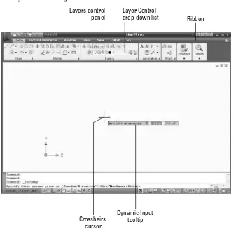
5. At the top of the screen, you see a tabbed palette filled with buttons, called the ribbon, which con-tains the Layers control panel(section) on the Home tab, as shown in Figure QS.2. From the Layer Control drop-down list in the Layers control panel, click the down-arrow and choose WINDOW, as shown in Figure QS.1. (Layers help you organize the objects in your drawing; I cover them in detail in Chapter 11.) Anything you draw will now be on the WINDOW layer.
FIGURE QS.1
Choose the WINDOW layer from the list of layers.
6. With your left mouse button (also called the pick button), choose Home tab➪Draw control panel➪Rectangle. (Using the ribbon is only one way to give AutoCAD and AutoCAD LT com-mands. I explain other ways in Chapter 3. You can find more about drawing lines and rectangles in Chapter 6.)
Move your mouse so that the cursor is in the main drawing area. Your screen should look like Figure QS.2. If you don’t see the tooltip bar — also called the Dynamic Input tooltip — near the cursor, then click the Dynamic Input button on the status bar at the bottom of your screen. 7. Follow these prompts to draw a rectangle that is 44" wide and 80" high.
Specify first corner point or [Chamfer/Elevation/Fillet/Thickness/ Width]: 0,0 ↵
Specify other corner point or [Area/Dimensions/Rotation]: 44,80 ↵
NOTE
NOTE
NOTE
FIGURE QS.2
Starting to draw a rectangle.
You see the full prompt shown here in the Command window at the bottom of your screen. You see an abbreviated version of the same prompt in the Dynamic Input tooltip that appears near the mouse cursor. In an architectural drawing, distances are assumed to be in inches, so you don’t need to specify a unit (although you can if you want).
Notice that the text that you type appears next to the cursor in the Dynamic Input tooltip. When you press Enter, the text that you typed is echoed in the Command Line window at the bottom of the screen.
8. To create a second rectangle inside the first one, choose Home tab➪Modify control panel➪
Offset. (I cover this and other editing commands in Chapters 9 and 10.) Follow these prompts:
Specify offset distance or [Through/Erase/Layer] <Through>: 4 ↵
Select object to offset or [Exit/Undo] <Exit>: Click the rectangle’s border to select it.
Specify point on side to offset or [Exit/Multiple/Undo] <Exit>: Click
NOTE
NOTE
Layer Control
drop-down list Ribbon Layers control
panel
Crosshairs cursor
9. You can draw from geometric points on objects such as endpoints and midpoints. (I explain how to specify coordinate points in Chapter 4.) To draw a line between the midpoints of the inner rec-tangle, choose Home tab➪Draw control panel➪Line, and follow these prompts:
Specify first point: Press and hold the Shift key and right-click. From the shortcut menu that opens, choose Midpoint. Place the cursor near the midpoint of the left side of the inner rectangle. When you see a triangle and the Midpoint tooltip, click.
Specify next point or [Undo]: Press and hold the Shift key and right-click. From the shortcut menu that opens, choose Midpoint. This time, place the cursor near the midpoint of the right side of the inner rectangle. When you see the Midpoint tooltip and triangle, click.
Specify next point or [Undo]: ↵
Your drawing should now look like Figure QS.3. (Your window should be green.)
FIGURE QS.3
The beginning of a window.
10. You will now draw a temporary construction line to help you find a starting point for the pane in the top of the window. Again, choose Home tab➪Draw control panel➪Line. Follow these prompts:
Specify first point: Press Shift and right-click. Choose Endpoint from the shortcut menu. Pick the left endpoint of the last line you drew.
Specify next point or [Undo]: 4,4 ↵. (This notation specifies that the endpoint of the line is 4 units above and to the right of the first point. Chapter 4 explains more about specifying coordinates in this manner.)
11. Again, choose Home tab➪Draw control panel➪Rectangle. Follow these prompts:
Specify first corner point or [Chamfer/Elevation/Fillet/Thickness/ Width]: Press Shift and right-click. Choose Endpoint and pick the final endpoint of the diagonal line you just drew.
Specify other corner point or [Area/Dimensions/Rotation]: 2’4”,2’4” ↵
This notation specifies 2 feet, 4 inches in the X and Y directions.
12. Choose Home tab➪Modify control panel➪Erase. At the Select objects:prompt, click the short, diagonal construction line that you drew in Step 9. The Select objects:prompt appears again. Press Enter to end the command. (Chapter 9 explains the ERASE command as well as other simple editing commands.)
13. Click the Ortho Mode button on the status bar at the bottom of the drawing area if it is not already selected (blue). The Ortho feature constrains drawing to right angles — either horizontal or vertical. (You can find more about Ortho in Chapter 4.)
14. To finish the bottom of the window, choose Home tab➪Draw control panel➪Line. Follow these prompts:
Specify first point: 8”,3’4” ↵
Specify next point or [Undo]: Move the mouse cursor down from the start point of the line. You see a temporary drag line. Then type the following length of the line. 2’8-7/16 ↵
You can see what you type in the Dynamic Input tooltip as you are typing. Therefore, you can check that you’ve typed the right numbers before you press Enter.
Specify next point or [Undo]: Move the cursor horizontally to the right and type 28 ↵.
Specify next point or [Close/Undo]: Now try entering the distance using decimal notation, instead of feet and inches. Move the cursor up and type 32.4375 ↵
Specify next point or [Close/Undo]: ↵
15. To draw shutters, first change the layer. Choose Home tab➪Layers control panel, click the Layer Control drop-down list, and choose EXWALL.
16. Choose Home tab➪Draw control panel➪Line. Follow the prompts:
Specify first point: Press Shift and right-click. Choose Endpoint from the shortcut menu. Click the upper-left corner of the window. Specify next point or [Undo]: Move the cursor to the left. Type 1’6” ↵
Specify next point or [Undo]: Move the cursor down. Type 6’8” ↵
Specify next point or [Close/Undo]: Type #0,0 ↵. (The pound sign ensures that your line goes to 0,0 no matter where you are.) Specify next point or [Close/Undo]: ↵
17. To draw the opposite shutter, you’ll mirror the first shutter that you just drew. (I cover the MIR-ROR command and many other editing commands in Chapter 10.) Choose Home tab➪Modify control panel➪Mirror, and follow these prompts:
Select objects: Click the three lines that make up the shutter. Select objects: ↵
TIP
TIP
NOTE
Specify first point of mirror line: Press Shift and right-click. Choose Midpoint from the shortcut menu.
Place the cursor near the middle of the top horizontal line of the window. Click when you see the triangle and Midpoint tooltip. Specify second point of mirror line: (The Ortho Mode button should
still be blue. If it isn’t, click it.) Move the cursor downward and pick any point.
Erase source objects? [Yes/No] <N>: ↵
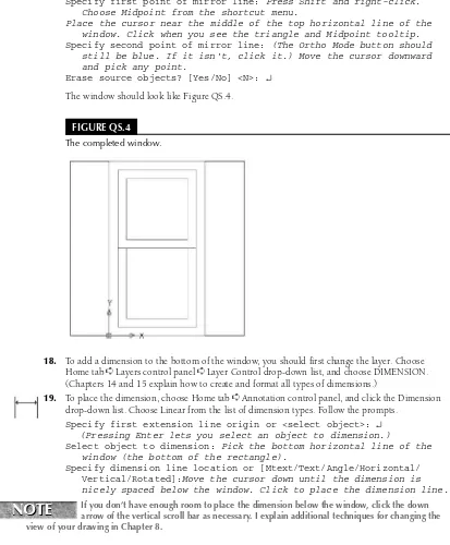
The window should look like Figure QS.4.
FIGURE QS.4
The completed window.
18. To add a dimension to the bottom of the window, you should first change the layer. Choose Home tab➪Layers control panel➪Layer Control drop-down list, and choose DIMENSION. (Chapters 14 and 15 explain how to create and format all types of dimensions.)
19. To place the dimension, choose Home tab➪Annotation control panel, and click the Dimension drop-down list. Choose Linear from the list of dimension types. Follow the prompts.
Specify first extension line origin or <select object>: ↵ (Pressing Enter lets you select an object to dimension.)
Select object to dimension: Pick the bottom horizontal line of the window (the bottom of the rectangle).
Specify dimension line location or [Mtext/Text/Angle/Horizontal/ Vertical/Rotated]:Move the cursor down until the dimension is nicely spaced below the window. Click to place the dimension line.
If you don’t have enough room to place the dimension below the window, click the down arrow of the vertical scroll bar as necessary. I explain additional techniques for changing the view of your drawing in Chapter 8.
NOTE
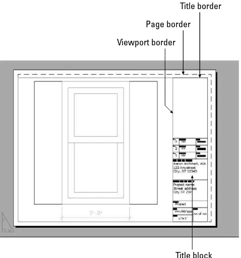
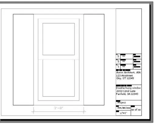
20. Click Save on the Quick Access toolbar at the upper-left corner of the window to save your work. 21. To prepare for printing, click the A Title Block-Landscape button, which is the second button
from the left in the right-hand group of buttons on the status bar at the bottom of your screen. You then see the window inside a titleblock and border, as shown in Figure QS.5. This titleblock and border come with the template to help you easily prepare the drawing for printing. (Chapter 17 explains how to lay out and print/plot a drawing.)
22. To set the scale for printing, click the magenta viewport border (labeled in Figure QS.5). Choose View tab➪Palettes control panel➪Properties. In the Properties palette’s Misc. section, click the Standard Scale item. (To see this item, you may have to scroll down in the Properties palette or enlarge it by dragging on its bottom and right edges. If the palette collapses to a thin bar, pass your cursor over the bar to expand it.) Click the down arrow that appears to the right of this item and check that the scale is set to 1" = 1'-0". Click the Close button at the top of the Properties palette. (I explain more about scales in Chapter 5.)
23. If the window and its dimension are not centered in the viewport window, double-click inside the viewport border. Then choose Home tab➪Utilities control panel➪Pan. Click and drag as neces-sary to center the window in the viewport. Press Esc to exit Pan mode. Double-click outside the viewport border to return to the layout.
FIGURE QS.5
The window with a titleblock as it appears on the Layout tab.
Page border Title border
Viewport border
24. To add some text to the titleblock, you need to zoom in. (I explain zooming in more detail in Chapter 8.) On the status bar at the bottom of your window, click Zoom. At the first prompt, click slightly above and to the left of the words Project Name. At the next prompt, click slightly below and to the right of the words City ST ZIP.
These words should now appear very large in the drawing area. They are already placed and for-matted, so all you need to do is replace them. (I explain all about how to create and edit text in Chapter 13.)
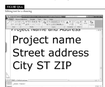
25. Double-click the Project nametext. A new Multiline Text tab appears, along with a ruler, as shown in Figure QS.6.
26. Select the text by dragging from the upper-left corner to the lower-right corner. Type the following: Double-hung window ↵
2010 Coral Lane ↵ Anytown, IA 12345
Click the Close button at the right end of the Multiline Text tab to close the In-Place Text Editor. 27. To return to your previous view, choose Home tab➪Utilities control panel➪Zoom (drop-down
list)➪Previous.
28. Click Save on the Quick Access toolbar to save your drawing.
FIGURE QS.6
29. You’re ready to print your drawing! Depending on your setup, either you can print directly to your printer, or if you have a plotter available, you can use that. (The layout is set up to fit on an 81⁄
2-x-11-inch or A-size sheet of paper.) Choose Plot on the Quick Access toolbar. The Plot dialog
box opens. (I cover printing and plotting in Chapter 17. Appendix A explains how to configure a printer or plotter.)
30. In the Printer/Plotter section of the Plot dialog box, click the Name drop-down list and choose the printer or plotter that you want to use.
31. Click the Preview button to open the preview window. You should see the window and its title-block laid out as shown in Figure QS.7.
FIGURE QS.7
Viewing the window in Preview mode.
If things don’t seem right, click the Close Preview Window button and review the previous steps to see if you can find the problem. Also, see the sidebar, “Help! My Drawing Doesn’t Look Like the Figure.”
32. Make sure your printer or plotter has an 81⁄2-x-11-inch or A-size sheet of paper, and click the Plot
button on the Preview window’s toolbar. Congratulations! You’ve just created and printed your first drawing!
33. Click the Close button at the upper-right corner of the AutoCAD application window to close both AutoCAD and the drawing. Click Yes to save your changes.
NOTE
It’s important to understand that this Quick Start tutorial used techniques that are easiest to understand for beginners; as a result, the techniques were sometimes a little awkward. AutoCAD and AutoCAD LT have many capabilities that make drawing easier and faster. You learn all these features in this book.
Summary
In this exercise, you practiced many of the skills that you need to use AutoCAD or AutoCAD LT effectively. Most of your work in AutoCAD or AutoCAD LT builds on these basic skills. The rest of the chapters in this book explain these procedures in more detail as well as many features not covered in this Quick Start exercise.
NOTE
NOTE
Help! My Drawing Doesn’t Look Like the Figure
I
f your drawing doesn’t look like the image shown in Figure QS.7, there could be several reasons. To fix the problem, try one of the following solutions: You may have made a mistake when creating the drawing. If you think that’s the case, start over and follow the prompts again.
You may have started AutoCAD or AutoCAD LT based on a template with different properties from the default. Be sure to use the template on theAutoCAD 2009 and AutoCAD LT 2009 Bible DVD, as explained in Step 2 of the previous exercise. Then follow the prompts again.
If your drawing still seems wrong, put the DVD that accompanies this book in your DVD drive. Choose Menu Browser➪File➪Open and use the Open dialog box to find abqs-01.dwgin the
Resultsfolder on the DVD. This drawing contains the end result of the exercise. You can try to find the difference between this drawing and yours. You can also copy abqs-01.dwgfrom the DVD to your hard drive and print or plot it.
I
n this chapter, I explain the essentials that you need to start drawings. After a little background, I discuss the basics of the screen that you see when you open AutoCAD or AutoCAD LT, and how to use it. If you’ve never used AutoCAD before, do the “Quick Start: Drawing a Window” chapter first.AutoCAD and its younger brother, AutoCAD LT, are both created by Autodesk. Together they are the most widely used technical drawing programs anywhere. AutoCAD alone has more than 6,000,000 registered users. According to Autodesk, CAD stands for computer-aided design,but it can also stand for computer-aided
draftingor drawing.
The first version of AutoCAD, running under DOS, came out in 1982. AutoCAD was the first significant CAD program to run on a desktop computer. At the time, most other technical drawing programs ran on high-end workstations or even mainframes. AutoCAD LT was introduced in 1993, as a less expensive alternative to AutoCAD, for people who don’t need all of AutoCAD’s advanced features.
AutoCAD’s Advantages
AutoCAD’s success has been attributed to its famous open architecture— the flexi-bility that the end user has to customize the program using source code files in plain text (ASCII) format — and programming languages (such as AutoLISP and Visual Basic for Applications).
As a result, AutoCAD is an extremely flexible drafting program, applicable to all fields. AutoCAD’s support for languages other than English, including those using other alphabets, is unparalleled, making AutoCAD highly popular abroad. As a result, AutoCAD is used in all disciplines and in more than 150 countries.
Through a high level of technical innovation and expertise, Autodesk has created a program with advanced features and capabilities, including 3D surface and
IN THIS CHAPTER
Getting acquainted with AutoCAD and AutoCAD LT
Starting AutoCAD and AutoCAD LT
Creating a new drawing
Using the AutoCAD and AutoCAD LT interface
Saving your drawing
solid modeling and visualization, access to external databases, intelligent dimensioning, importing and exporting of other file formats, Internet support, and much more.
The major disciplines that use AutoCAD are:
Architectural, Engineering, and Construction (AEC)
Mechanical
Geographic Information Systems (GIS)
Surveying and Civil Engineering
Facilities Management
Electrical/electronic
Multimedia
However, AutoCAD has many other lesser-known uses, such as pattern making in the garment industry, sign making, and so on. In this book, I provide examples from several fields. The world of AutoCAD is very broad, and you can learn from seeing the many approaches that AutoCAD makes possible.
Comparing AutoCAD and AutoCAD LT
AutoCAD LT’s advantages are its lower cost and its compatibility with AutoCAD. The programming code that is used to create AutoCAD LT is a subset of the code used in AutoCAD. Here are the major differences between AutoCAD and AutoCAD LT:
AutoCAD includes features that enable CAD managers to hold drawings to certain standards, such as for layer names and text styles. AutoCAD LT doesn’t contain these features.
AutoCAD LT is not as customizable as AutoCAD, which is both programmable and fully cus-tomizable. It also doesn’t include the Action Recorder.
AutoCAD LT includes minimal options for 3D; AutoCAD includes a full-featured 3D capability.
AutoCAD LT has fewer presentation features than AutoCAD, which includes gradient fills and 3D rendering.
AutoCAD LT is deployable on a network but does not have AutoCAD’s network license manage-ment feature that includes reporting and flexible licensing.
AutoCAD LT does not offer the database connectivity feature, but you can use tables to connect to data in a Microsoft Office Excel file; AutoCAD offers the flexibility to connect to other types of databases, create labels from the data, and so on.
AutoCAD LT does not include AutoCAD’s quick-dimensioning feature, which allows you to quickly insert a number of dimensions, one after the other.
AutoCAD LT does not come with Express Tools, a set of additional routines that ship with AutoCAD.
Starting AutoCAD and AutoCAD LT
This section starts a quick tour of AutoCAD and AutoCAD LT. The first step is to start the program.
The DVD contains a 30-day trial version of AutoCAD 2009 and AutoCAD LT 2009.
This book covers AutoCAD 2009 and AutoCAD LT 2009 running on Windows XP Home/Professional, or Windows Vista. (Most of the figures were taken in Windows Vista.) Every computer is set up somewhat dif-ferently, so you may need to adjust the following steps slightly. If you didn’t install the software yourself and are unfamiliar with the folders (also called directories) on your computer, get help from someone who is familiar with your computer system.
If you need information on installing AutoCAD or AutoCAD LT, see Appendix A. Appendix A also covers configuring the software and printers or plotters.
By default, installing AutoCAD or AutoCAD LT places a shortcut on your desktop. You can double-click one of the shortcuts to launch the program that is installed on your machine, or use the Start menu to choose one of the following:
For AutoCAD: Start➪All Programs➪Autodesk➪AutoCAD 2009➪AutoCAD 2009
For AutoCAD LT: Start➪(All) Programs➪Autodesk➪AutoCAD LT 2009➪AutoCAD LT 2009
Creating a New Drawing
After you launch AutoCAD or AutoCAD LT, it automatically opens a new drawing named Drawing1.dwg. You can see the drawing name on the title bar. You can start drawing immediately. In Chapter 2, I explain how to start a drawing based on a template and how to open an existing drawing.
STEPS: Starting AutoCAD or AutoCAD LT
1. Click Start on the Windows task bar at the bottom of your screen. 2. Choose one of the following:
For AutoCAD:Start➪(All) Programs➪Autodesk➪AutoCAD 2009➪AutoCAD 2009
For AutoCAD LT: Start➪(All) Programs➪Autodesk➪AutoCAD LT 2009➪AutoCAD LT 2009
You see a blank drawing named Drawing1.dwg.
If you are continuing with this chapter, keep this drawing open. I cover exiting from AutoCAD and AutoCAD LT later in this chapter.
Using the AutoCAD and AutoCAD LT Interface
AutoCAD offers three quite different preset workspaces, depending on how you want to work. For example, these workspaces determine the ribbon components, toolbars, and other interface items that you see. AutoCAD offers both 2D and 3D environments. The 3D environment is quite different from the AutoCAD LT screen, but the AutoCAD 2D and the AutoCAD LT environments are similar. In this section, I discuss the