Bandung, 2019
Rekayasa Pondasi II
Dosen : Sherly Meiwa ST., MT.
Jurusan Teknik Sipil
Pile Foundation
Contoh Proyek
DESAIN STRUKTUR
DAN PONDASI TANKI 610-TK-213 AREA OM PT. PERTAMINAPERSERO RU II DUMAI
Tank Diameter : 48310 mm
Tank Height : 12240 mm
Pile Cap/Slab Diameter : 48310 mm Tank Steel Thickness : 20 mm
Capacity : 10000 kL
Unit weight of Solar : 8.7 kN/m3 Unit weight of water : 10 kN/m3
Outline
Contoh Proyek
DESAIN STRUKTUR
DAN PONDASI TANKI 610-TK-213 AREA OM PT. PERTAMINAPERSERO RU II DUMAI
Tank Diameter : 48310 mm
Tank Height : 12240 mm
Pile Cap/Slab Diameter : 48310 mm Tank Steel Thickness : 20 mm
Capacity : 10000 kL
Unit weight of Solar : 8.7 kN/m3 Unit weight of water : 10 kN/m3
Contoh Proyek
-60 -50 -40 -30 -20 -10 0
0 20 40 60
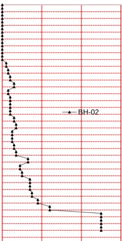
Depth (m) BH-02
No. Jenis Tanah Kedalaman (m) NSPT (avg)
g ’
(kN/m3)
Kohesif (cu) (kN/m2)
Friction
Angle (f) E50 (kN/m2)
1 Organic Clay 00.00 – 03.00 1 4.8 6 0 0.02
2 Very Soft Clay 03.00 – 17.00 1 7 6 0 0.02
3 Soft Clay 17.00 – 32.00 4 9.2 22 0 0.02
4 Soft to Medium
Clay 32.00 – 52.00 8
8.2 49 0 0.01
5 Stiff Clay 52.00 - 60.00 24 9 96 0 0.005
6 Hard Clay 60.00-66.00 50 19 144 0 0.004
Tabel 3.5 Parameter Tanah Desain
Parameter Tanah Desain
Contoh Proyek
Type of Foundation
Load [kN] Allowable Single Pile Capacity
[kN] Efficienc
y
Number Of Pile AFTER
Design
(SERVICE LOAD) (ULTIMATE LOAD)
Service Load
Ultimate Load
Service Load
(Operating) Ultimate Load Group pile
Status Group pile
Status
Contoh Proyek
Contoh Proyek
-70 -60 -50 -40 -30 -20 -10 0
0 500 1000 1500 2000 2500 3000 3500
Depth (m)
Allowable Service Load (kN)
Bearing Capacity SPUN Pile D600
-70 -60 -50 -40 -30 -20 -10 0
0 20 40 60
Depth (m)
SPT, Blows/ft
BH-02
Contoh Proyek
Type of Foundation
Diameter [mm]
Thickness [mm]
Embedded Length [m]
Ultimate Axial Capacity to Single Pile [kN]
Load [kN] Allowable Single Pile Capacity [kN] Number Of Pile before efficiency
Service Load (Hydrostest)
Service Load
(Operating) Ultimate Load
Service Load (Hydrostatic)
Service Load
(Operating) Ultimate Load Service Load (Hydrostest)
Service Load (Operating)
Ultimate
SF=2 sf=2.5 sf=1.67 Load
Spun Pile 600 100 60 3148 250284 219295 333000 1574.119 1259.295 1885.17 159 174 177
Steel Pipe Pile 700 12 60 3794 250284 219295 333000 1897.0 1517.6 2271.9 132 145 147
Type of Foundation Diameter [mm]
Allowable Single Pile Capacity [kN]
Spacing
minimum of Pile Xd Efficiency
Number Of Pile AFTER efficiency Service Load
(Hydrostatic)
Service Load
(Operating) Ultimate Load Service Load Service Load
Diameter tiang = 600 mm
Jumlah Tiang = 224 tiang
Kedalaman Tiang = 60 m
Langkah Awal sebelum Mendesain adalah
menentukan Parameter tanah
Field Soil Investigation
Laboratory Test
-70 -60 -50 -40 -30 -20 -10 0
0 20 40 60
Depth (m) BH-02
No. Jenis Tanah Kedalaman (m) NSPT (avg)
g ’
(kN/m3)
Kohesif (cu) (kN/m2)
Friction
Angle (f) E50 (kN/m2)
1 Organic Clay 00.00 – 03.00 1 4.8 6 0 0.02
2 Very Soft Clay 03.00 – 17.00 1 7 6 0 0.02
3 Soft Clay 17.00 – 32.00 4 9.2 22 0 0.02
4 Soft to Medium
Clay 32.00 – 52.00 8
8.2 49 0 0.01
5 Stiff Clay 52.00 - 60.00 24 9 96 0 0.005
6 Hard Clay 60.00-66.00 50 19 144 0 0.004
Desain Parameter tanah Grafik NSPT
Introduction
Piles are structural members that are made of steel, concrete,
or timber. They are used to build pile foundations, which are
deep and which cost more than shallow foundations
Introduction
a) Kondisi lapisan tanah atas memiliki kompressibilitas tinggi dan kurang kuat memikul distribusi beban dari struktur atas. Pile berfungsi untuk mendistribusikan beban ke lapisan batuan atau tanah yang lebih kuat.
b) Jika lapisan tanah keras cukup jauh dari permukaan tanah. Pile dapat digunakan untuk mentransfer beban struktur ke tanah secara bertahap. Kemampuan tiang menahan beban berasal dari tahanan friksi yang terbentuk dari interface antara tiang+tanah.
The following list identifies some of the conditions that require pile foundations (Vesic, 1977):
Introduction
c) Tiang mampu menahan tekuk
(resist to bending) di saat yang
sama juga menahan beban vertical
dari struktur atas. Kondisi ini terjadi
saat terdapat struktur sangat tinggi
yang memiliki dampak signifikan
terhadap beban gempa dan beban
angin
Introduction
d) Kondisi berada di tanah yang
mudah runtuh atau tanah ekspansif
(mengembang). Penggunaan pile
menjadi alternatif untuk kondisi
zona aktif ini
Introduction
e) Pile juga digunakan untuk menahan beban
uplift untuk beberapa struktur seperti tower
transmisi, platform offshore, dan alas
basement yang berada dibawah permukaan
air tanah
Introduction
f) Abutment jembatan dan piers
biasanya juga menggunakan pile
foundation untuk menghindari
hilangnya kapasitas daya dukung
Pile Foundation
Type of Piles and Their Structural Characteristics
Different types of piles are used in construction work, depending on the type of load to be carried, the subsoil conditions, and the location of the water tables.
Piles can be divided into the following categories:
(a) Steel piles
(b) Concrete piles
(c) Wooden (timber) piles
Type of Piles and Their Structural Characteristics
Steel Pile
Steel piles generally are either pipe
piles or rolled H-section piles. Pipe
piles can be driven into the ground with
their ends open or closed. In many
cases, the pipe piles are filled with
concrete after they have been driven.
When necessary, steel piles are spliced by welding or by riveting.
a) Figure shows a typical splice by welding for an H-pile
b) Figure shows b typical splice by welding for a pile piles.
c) Figure shows c diagram of splice of an H-pile by rivets or bolts.
Type of Piles and Their Structural Characteristics
Steel Pile
When hard driving conditions are expected, such as driving through dense gravel, shale, or soft rock, steel piles can be fitted with driving points or shoes.
Figures (d) and (e) shows diagram of two types of shoe for pipe piles.
Type of Piles and Their Structural Characteristics
Steel Pile
Steel Pile dapat mengalami korosif misalnya akibat rawa, gambut, dan tanah organik lainnya yang bersifat korosif.
Untuk mengatasi ini biasanya direkomendasikan untuk menambah ketebalan baja (melebihi ketebalan penampang yang didesain). Pada keadaan lain dari pabriknya sudah diberi lapisan epoxy yang cukup baik untuk menahan korosif, yang mana lapisan ini juga tidak mudah rusak saat dipancang. Selain itu alternatif lain dapat membungkus baja dengan beton di zona korosifnya.
Type of Piles and Their Structural Characteristics
Steel Pile
Kelebihan :
1. Mudah dipotong atau ditambah ukuran panjang tiang
2. Bisa berdiri pada kondisi tegangan yang besar akibat pemancangan 3. Bisa menembus lapisan keras seperti kerikil padat dan batuan lunak 4. Mampu memikul kapasitas beban yang besar
Kekurangan : 1. Relatif mahal
2. Menimbulkan kebisingan 3. Rentan korosif
Type of Piles and Their Structural Characteristics
Steel Pile
Concrete piles may be divided into two basic categories:
(a) precast piles
and (b) cast-in-situ piles.
Type of Piles and Their Structural Characteristics
Concrete Pile
Precast piles adalah pile yang sudah disiapkan (Pile fabrikasi) dengan besar perkuatan sudah ditentukan pada umumnya, penampang dapat berupa segiempat atau oktagonal.
Keuntungan :
a. Bisa untuk pemancangan pada tanah keras
b. Tahan korosif
c. Mudah dikombinasikan dengan struktur beton lainnya
Kerugian :
a. Sulit untuk dilakukan pemotongan
b. Transportasi sulit
Type of Piles and Their Structural Characteristics
Precast Concrete Pile (Tiang Pancang Beton)
Cast-in-situ atau cast-in-place, adalah pile yang dibentuk dengan membuat lubang pada tanah, dilakukan pemasangan tulangan lalu diisi dengan beton.
Pile ini dibagi dalam dua kategori yaitu :
1. pile dengan casing (cased) dan 2. pile tanpa casing (uncased)
Type of Piles and Their Structural Characteristics
Cast In situ Concrete Pile (Bored pile)
Pile dengan casing dibuat dengan memancang casing baja ke dalam tanah. Saat pile sudah mencapai kedalaman yang mencukupi, casing diisi dengan beton (bisa sebelumnya ditambah tulangan)
Type of Piles and Their Structural Characteristics
Cased Cast In situ Concrete Pile
Keuntungan :
1. Relatif murah
2. Kondisi Tanah bisa diselidiki setelah pemasangan casing dan sebelum pengisian beton
3. Mudah untuk diperpanjang
Kelemahan :
1. Sulit disambung jika telah dicor beton
2. Casing rentan mengalami kerusakan selama pemancangan
Type of Piles and Their Structural Characteristics
Cased Cast In situ Concrete Pile
Type of Piles and Their Structural Characteristics
UnCased Cast In situ Concrete Pile
Uncased Pile dibuat dengan memancang casing baja pada
kedalaman yang telah ditentukan, saat dituangkan beton segar,
casing ditarik secara bertahap
Type of Piles and Their Structural Characteristics
UnCased Cast In situ Concrete Pile
Keuntungan :
1. Pada awalnya lebih ekonomis
2. Bisa diselesaikan pada berbagai elevasi kedalaman Kelemahan :
1. Pori bisa tercipta jika pengisian beton terlalu cepat 2. Sulit disambung jika telah dibeton
3. Pada tanah lunak, beberapa kasus sisi lubang dapat runtuh.
4. Pada kondisi tertentu, terdapat rongga besar dalam tanah
(berupa lensa tanah), hal ini merugikan karena harus diisi
Type of Piles and Their Structural Characteristics
Timber Pile
Timber pile adalah tiang dari kayu, maximal Panjang tiang hanya 10-20 m.
Kualitas kayu yang digunakan sebagai timber pile harus lurus, mulus, tanpa cacat. Timber pile tidak bisa menahan tegangan pemancangan terlalu besar sehingga kapasitas tiang cukup terbatas. Beberapa kasus diberikan sepatu baja (steel shoes) untuk menghindari kerusakan pada ujung tiang
Kepala atau bagian atas timber piles juga bisa mengalami kerusakan selama
pemancangan. Untuk menghindari hal ini bagian atas tiang diberikan pengikat
berbahan metal atau topi tiang
Type of Piles and Their Structural Characteristics
Composite Pile
Porsi bagian atas atau bawah tiang komposit
dibuat dari material yang berbeda. Contohnya,
tiang komposit dapat berupa baja + beton
atau kayu+beton. Untuk tiang komposit
baja+beton terdiri atas porsi lebih rendah baja
dan porsi lebih atas cast in place concrete.
Estimating Pile Length
Pile terbagi atas tiga kategori berdasarkan panjang dan mekanisme transfer beban di dalam tanah.
1. Point bearing piles 2. Friction piles
3. Compaction piles
Estimating Pile Length
Estimating Pile Length
Kapasitas tiang bergantung sepenuhnya pada kapasitas daya dukung material tanah dasar di ujung tiang yang disebut point bearing pile.
Dalam banyak kasus Panjang tiang mencukupi hingga sampai tanah dasar
Point bearing pile
Estimating Pile Length
Kondisi saat tidak ada lapisan tanah keras di dasar ujung tiang sehingga pile didesain sangat panjang dan tidak ekonomis. Pada tipe subsoil ini, tiang dipancang menembus tanah lunak hingga kedalaman tertentu.
Daya dukung ijin tiang dapat di lihat pada rumus di bawah ini. Dimana nilai daya dukung ujung Qp relative kecil.
Friction piles
Estimating Pile Length
Compaction piles
Equations for Estimating Pile Capacity
Equations for Estimating Pile Capacity
Q
p= A
px q
pQ
s= A
sx q
sKapasitas
daya dukung
Daya dukung ujung (Point bearing capacity)
Luas area daya dukung per unit
Daya dukung tahanan friksi (friction resistance) Ap = luas penampang pile
As = luas selimut pile
Daya dukung ultimate Daya dukung ijin
Equations for Estimating Pile Capacity
Point bearing capacity, Qp
Kohesif tanah
Tegangan Vertikal efektif
Dimensi tiang
Q
p= A
px q
p Daya dukung ujung (Point bearing capacity) Ap = luas penampang pileEquations for Estimating Pile Capacity
Equations for Estimating Pile Capacity
Point bearing Capacity, Qp
Frictional Resistance, Qs
Estimating Point Bearing Capacity, Qp
Estimating Point Bearing Capacity, Qp
Meyerhof’s method for estimating Qp in SAND
Estimating Point Bearing Capacity, Qp
Meyerhof’s method for estimating Qp in SAND
Meyerhof’s method for estimating Qp in Clay
Estimating Qp in SAND
Estimating Qp in CLAY
Estimating Qp in CLAY
PROBLEM
Estimating Friction Resistance, Qs
Estimating Friction Resistance (Qs) in SAND
Friction Resistance in Sand
The frictional resistance (Qs):
The unit frictional resistance (f), is hard to estimate. In making an estimation of f, several important factor must be kept in mind:
1. The nature of the pile installation. For driven piles in
sand, the vibration caused during pile driving helps
density the soil around the pile. Figure shows the
contours of the soil friction angle f’ around a driven
pile.
Estimating Friction Resistance (Qs) in SAND
Friction Resistance in Sand
2. It has been observed that the nature of variation of f in field is approximately as shown in Figure. The unit skin friction increased with depth more or less linearly to a depth of L’
and remains constant thereafter.
L’ = 15D.
3. At similar depths, the unit skin friction in loose sand is higher for a high- displacement pile, compared with a low- displacement pile.
4. At similar depths, bored, or jetted, piles will have a lower
unit skin friction compared with driven piles.
Estimating Friction Resistance (Qs) in SAND
Taking into account the preceding factors, we can give the following approximate relationship for f (see Figure 9.16):
For z = 0 to L’
For z = L’ to L
Friction Resistance in Sand
Estimating Friction Resistance (Qs) in SAND
Estimating Friction Resistance (Qs) in SAND
Estimating Friction Resistance (Qs) in SAND
20 m
15 D = 6.1 m 0 kN/m2
75.9 kN/m2
Qs = As x fs Qs = Qs1+ Qs2
As1= (0.407 x 4) 6.1 = 9.93 m2 Qs1= 9.93 x 75.9 / 2 = 376.874 kN
I
II
As2= (0.407 x 4) (20-6.1) = 22.63 m2 Qs2= 22.63 x 75.9 = 1717.56 Kn Qs = Qs + Qs
Daya dukung Ijin, Qall
𝑄 𝑎𝑙𝑙 = 𝑄 𝑝 +𝑄 𝑠
𝐹 𝑆 = 829 𝑘𝑁+2094 𝑘𝑁 3
𝑄 𝑎𝑙𝑙 = 974.33 𝑘𝑁
Example 9.5 Example 9.1
PROBLEM 1
Estimating Friction Resistance (Qs) in CLAY
Friction Resistance in Clay
Estimating the frictional (or skin) resistance of piles in clay is almost as difficult a task as estimating that in sand, due to the presence of several variables that cannot easily be quantified. Several methods for obtaining the unit frictional resistance of piles are described in the literature:
1. l Method
2. a Method
3. b Method
Estimating Friction Resistance (Qs) in CLAY
Frictional Resistance (Qs) in Clay l Method
This method, proposed by Vijayvergiya and Focht (1972), is based on the assumption that the displacement of soil caused by pile driving results in a passive lateral pressure at any depth and that the average unit skin resistance is:
The value of l changes with the depth of penetration of the pile. The total
frictional resistance may be calculated as:
Estimating Friction Resistance (Qs) in CLAY
Frictional Resistance (Qs) in Clay l Method
The mean effective stress :
Estimating Friction Resistance (Qs) in CLAY
Frictional Resistance (Qs) in Clay a Method
The unit skin resistance in clayey soils can be represented by the equation:
where a = empirical adhesion factor
Estimating Friction Resistance (Qs) in CLAY
Frictional Resistance (Qs) in Clay a Method
Estimating Friction Resistance (Qs) in CLAY
Frictional Resistance (Qs) in Clay b Method
When piles are driven into saturated clays, the pore water pressure in the soil around the
piles increases. The excess pore water pressure in normally consolidated clays may be four
to six times cu . However, within a month or so, this pressure gradually dissipates. Hence,
the unit frictional resistance for the pile can be determined on the basis of the effective
stress parameters of the clay in a remolded state (c’ = 0). Thus, at any depth,
Resume daya dukung aksial tiang tunggal
Sand Clay
L’ = 15D.
d‘ = 2/3 to 4/5 f’
a Method
b Method
l Method
EXAMPLE
EXAMPLE (solution)
EXAMPLE (solution)
EXAMPLE (solution)
EXAMPLE (solution)
PROBLEM 2 (Home work)
Nspt Parameter
Estimating Point Bearing Capacity, Qp
Nspt Parameter
Daya Dukung Ujung Tiang Pancang untuk tanah Pasir
Daya Dukung Ujung Tiang Pancang untuk tanah Pasir
Meyerhoff Theory
Daya Dukung Ujung Tiang Bor untuk tanah Pasir
Qp = 7 N (t/m
2) < 400 (t/m
2)
Daya Dukung Ujung Tiang Bor untuk tanah Pasir
Qp = 7 N (t/m
2) < 400 (t/m
2)
Daya Dukung Ujung Tiang Bor dan Tiang Pancang untuk tanah Lempung
Estimating Friction Capacity, Qs
Nspt Parameter
Daya Dukung Friksi Tiang Pancang dan Tiang Bor untuk tanah Pasir
Daya Dukung Friksi Tiang Pancang dan Tiang Bor untuk tanah Pasir
N60
N60
N 60
Faktor koreksi NSPT yaitu (N1)60 , (N1)60 adalah kondisi terkoreksi 1 atm dan 60%energi hammer
Nilai CN Maximum = 1.7 NSPT
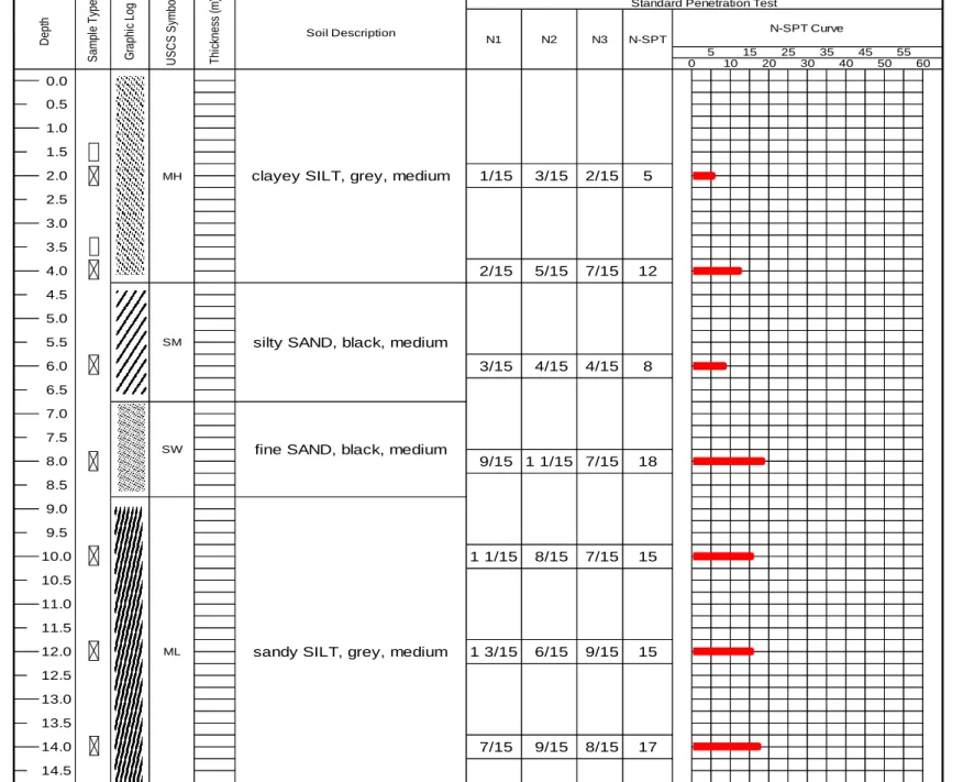
ML
Depth
35 30
N2 N3
Sample Type
Soil Description
Thickness (m)
USCS Symbol
Graphic Log Standard Penetration Test
9/15
N1
N-SPT Curve N-SPT
3/15
9/15 1 1/15 8/15
6/15 0.0
9.0 7.5 8.0 1.5
5.0 0.5 1.0
2.0
8.5
1 1/15 7/15 4/15 4/15 2/15 5/15 7/15
25
40
1/15 3/15
12 5 2/15
18
15 15 7/15 2.5
3.5 4.0 4.5 3.0
5.5 6.0 6.5 7.0
11.0 11.5 12.0 9.5 10.0 10.5
1 3/15
5 10
15
8
20
0 50
55
sandy SILT, grey, medium
MH
SM
60 45
SW
clayey SILT, grey, medium
silty SAND, black, medium
fine SAND, black, medium
Daya Dukung Friksi Tiang Pancang dan Tiang Bor untuk tanah Pasir
GWL = 20 m D = 0.5 m 10 D = 5
fR = 20 degrees 4 D = 2
D tiang = 16 in circle Beban = 17 lantai (1 lantai asumsi 2 ton/m2)
15D = 240 m Asumsi beban single pile = 340 kN/m2 340 -1
FS= 2.5 340 -15
Depth g' so'
Q
ultQ
allm kN/m3 kN/m2
C
NC
EC
BC
RC
S N des a i n QP (ton) Qp (kN) fs (kN/m2) Qs (kN) kN kN1 S 15.5 15.5 0 1.623616 0.8 1.05 0.8 1 0.0000 2.448 19.224 192.241 0.000 0.000 192.241 76.896 2 S 15.5 31 5 1.456954 0.8 1.05 0.8 1 4.8954 4.911 38.574 385.737 9.791 15.379 401.116 160.446 3 S 15.5 46.5 5 1.466471 0.8 1.05 0.8 1 4.9273 7.353 57.752 577.518 9.855 30.859 608.377 243.351 4 S 17 68 12 1.212678 0.8 1.05 0.8 1 9.7790 9.263 72.750 727.501 19.558 61.581 789.082 315.633 5 S 17 85 12 1.084652 0.8 1.05 0.8 1 8.7466 7.161 56.240 562.396 17.493 89.059 651.455 260.582 6 S 15.5 93 8 1.036952 0.8 1.05 0.8 1 5.5747 5.368 42.159 421.593 11.149 106.572 528.165 211.266 7 S 15.5 108.5 8 0.960031 0.8 1.05 0.8 1 5.1611 7.767 60.999 609.994 10.322 122.787 732.780 293.112 8 S 17 136 18 0.857493 0.8 1.05 0.8 1 10.3722 10.076 79.134 791.339 20.744 155.372 946.710 378.684 9 S 17 153 18 0.808452 0.8 1.05 0.8 1 9.7790 8.755 68.762 687.618 19.558 186.094 873.711 349.485 10 S 17 170 15 0.766965 0.8 1.05 0.8 1 7.7310 7.551 59.306 593.063 15.462 210.381 803.445 321.378 11 S 17 187 15 0.731272 0.8 1.05 0.8 1 7.3712 7.214 56.661 566.611 14.742 233.539 800.150 320.060
Q
sQ
PN
sptFactor
(N
1)
60Soil
Type Nspt
Daya Dukung Friksi Tiang Pancang dan Tiang Bor untuk tanah Pasir
Korelasi Nspt dan g
Depth g' so'
Q
ultQ
allm kN/m3 kN/m2
C
NC
EC
BC
RC
S N des a i n QP (ton) Qp (kN) fs (kN/m2) Qs (kN) kN kN1 S 15.5 15.5 0 1.623616 0.8 1.05 0.8 1 0.0000 2.448 19.224 192.241 0.000 0.000 192.241 76.896 2 S 15.5 31 5 1.456954 0.8 1.05 0.8 1 4.8954 4.911 38.574 385.737 9.791 15.379 401.116 160.446 3 S 15.5 46.5 5 1.466471 0.8 1.05 0.8 1 4.9273 7.353 57.752 577.518 9.855 30.859 608.377 243.351 4 S 17 68 12 1.212678 0.8 1.05 0.8 1 9.7790 9.263 72.750 727.501 19.558 61.581 789.082 315.633 5 S 17 85 12 1.084652 0.8 1.05 0.8 1 8.7466 7.161 56.240 562.396 17.493 89.059 651.455 260.582 6 S 15.5 93 8 1.036952 0.8 1.05 0.8 1 5.5747 5.368 42.159 421.593 11.149 106.572 528.165 211.266 7 S 15.5 108.5 8 0.960031 0.8 1.05 0.8 1 5.1611 7.767 60.999 609.994 10.322 122.787 732.780 293.112 8 S 17 136 18 0.857493 0.8 1.05 0.8 1 10.3722 10.076 79.134 791.339 20.744 155.372 946.710 378.684 9 S 17 153 18 0.808452 0.8 1.05 0.8 1 9.7790 8.755 68.762 687.618 19.558 186.094 873.711 349.485 10 S 17 170 15 0.766965 0.8 1.05 0.8 1 7.7310 7.551 59.306 593.063 15.462 210.381 803.445 321.378 11 S 17 187 15 0.731272 0.8 1.05 0.8 1 7.3712 7.214 56.661 566.611 14.742 233.539 800.150 320.060 12 S 17 204 15 0.70014 0.8 1.05 0.8 1 7.0574 6.919 54.342 543.415 14.115 255.710 799.125 319.650
Q
sQ
PN
sptFactor
(N
1)
60Soil
Type Nspt
Daya Dukung Friksi Tiang Pancang dan Tiang Bor untuk tanah Pasir
-14 -13 -12 -11 -10 -9 -8 -7 -6 -5 -4 -3 -2 -1 0
0 100 200 300 400
Depth (m)
Daya Dukung Izin Tekan (kN)
D = 0.5 m
Beban = 17 lantai (1 lantai asumsi 2 ton/m2) Asumsi beban single pile = 340 kN/m2
Untuk beban 17 lantai, dibutuhkan single pile
ukuran diameter 0.5 meter dengan Panjang tiang 8m
Daya Dukung Friksi Tiang Pancang dan Tiang Bor untuk tanah Pasir
Untuk beban 20 lantai, dibutuhkan single pile
ukuran diameter 0.5 meter dengan Panjang tiang 8m
Solution Assignment #4
-26 -25 -24 -23 -22 -21 -20 -19 -18 -17 -16 -15 -14 -13 -12 -11 -10 -9 -8 -7 -6 -5 -4 -3 -2 -1 0
0 200 400 600
Depth (m)
Daya Dukung Izin Tekan (kN)
Korelasi Empiris Nilai N -SPT dan Berat Jenis Tanah g untuk
Tanah Pasir dan Lempung
Korelasi Empiris Nilai N-SPT dan Berat Jenis Tanah g untuk
Tanah Pasir dan Lempung
Negative Skin Friction
Negative Skin Friction adalah gaya tarik ke bawah pada tiang akibat tanah disekitar tiang. Gaya ini terjadi akibat kondisi sebagai berikut :
1. Jika muatan tanah lempung berada di atas
lapisan tanah granular (pasir), Muatan inin secara
bertahap akan mengalami konsolidasi. Proses
konsolidasi ini akan menarik muatan clay ke
bawah tiang selama waktu konsolidasi.
Negative Skin Friction
2. Jika muatan tanah granular berada di atas tanah lempung lunak. Akan menyebabkan proses konsolidasi pada lapisan tanah lempung sehingga lapisan tanah sand ikut bergerak ke bawah
3. Kondisi muka air tanah yang rendah dapat
meningkatkan tegangan efektif vertical pada
tanah di kedalaman tertentu. Yang mana
akan menyebabkan penurunan konsolidasi di
lempung. Jika tiang berada pada lapisan
tanah lempung, akan dikenakan gaya
menarik kebawah.
Negative Skin Friction
Negative Skin Friction
Negative Skin Friction
Negative Skin Friction
Group Pile Efficiency
In most cases, piles are used in groups to transmit the structural load to the soil. A pile cap is constructed over group piles. The cap can be in contact with the ground, as in most cases, or well above the ground, as in the case of offshore platforms.
When the piles are placed close each other, a reasonable
assumption is that the stresses transmitted by the piles to soil will
overlap and reducing the load-bearing capacity. Ideally, the piles
in a group should be spaced so that the load-bearing capacity of
the group is not less than the sum of the bearing capacity of the
individual piles. In practice, the minimum center-to-center pile
spacing, d, is 2.5D and, in ordinary situations, is actually about 3
to 3.5D.
Group Pile Efficiency
The efficiency of the load-bearing capacity of a group pile may be defined as :
Group Pile Efficiency
Group Pile Efficiency
Perimeter blok Pile group Jumlah tiang arah L = n1 Jumlah tiang arah B = n2 2 sisi Lg = 2 {(n1-1)d + D}
2 sisi Bg = 2 {(n2-1)d + D}
2 Sisi Lg+ 2 sisi Bg =
2 {(n1-1)d + D} + 2 {(n2-1)d + D}
2 {(n1+n2-2d) + 2D}
Group Pile Efficiency
Group Pile Efficiency
Group Pile Efficiency
Keliling blok tiang (blok group pile)
Group Pile Efficiency
Group Pile Efficiency
Group Pile Efficiency
Group Pile Efficiency
n1 = 2
n2 = 3
d = 0.9 m
D = 0.45 m
Perimeter single pile = p . D
= 2 2+3−2 0.9+(4 ∗ 0.45)
3.14 ∗0.45 ∗2 ∗3 = 84,9 %
Misal masing-masing tiang memiliki daya dukung 300kN.
Jumlah daya dukung seluruh tiang = 2 x 3 x 300 kN= 1800kN Daya dukung pile group setelah dikali dengan efisiensi group tiang 1800kN x = 1800 x 84.9 % = 1528 kN
p . D