64:4 (2013) 125–130 | www.jurnalteknologi.utm.my | eISSN 2180–3722 | ISSN 0127–9696
Teknologi
Phenol Removal from Water by Pulsed Power Discharge: A Review
Hashem Ahmadia, Muhammad Abu Bakar Sidika,b*, Mehrdad Khamooshic, Zulkafle Buntata
aInstitut Voltan dan Arus Tinggi (IVAT) and Faculty of Electrical Engineering, Universiti Tenologi Malaysia, 81310 UTM Johor Bahru, Johor, Malaysia bDepartment of Electrical Engineering, Faculty of Engineering, Universitas Sriwijaya, 30662 Inderalaya, Ogan Ilir, South Sumatera, Indonesia cDepartment of Mechanical Engineering, Eastern Mediterranean University, G.magusa, TRNC, Mersin10 ,Turkey
*Corresponding author: abubakar@fke.utm.my
Article history
Received :15 February 2013 Received in revised form : 10 June 2013
Accepted :16 July 2013
Graphical abstract
Abstract
In the last three decades, pulsed high voltage discharge technology has offered promising techniques for the treatment of wastewaters released to the environment by industry. A significant effort has been directed towards understanding the processes that occur during the discharge of solutions for a variety of reactor configurations. This review presents the disadvantages and advantages of different reactors based on discharge phase. Detailed information is also provided on the principals used in each technique and the advantages and disadvantages associated with each method. Finally, a discussion on the different discharge areas is presented.
Keywords: Phenol removal; pulsed streamer discharge; advanced oxidation process
Abstrak
Tiga dekad yang lalu, nyahcas dedenyut voltan tinggi telah menawarkan suatu teknik yang boleh menjanjikan hasil yang baik untuk rawatan air sisa buangan yang dilepaskan ke persekitaran oleh industri. Satu usaha penting telah ditujukan ke arah memahami proses yang berlaku semasa menunaikan penyelesaian bagi pelbagai konfigurasi reaktor. Ulasan ini membentangkan kelemahan dan kelebihan reaktor yang berbeza berdasarkan fasa pelepasan. Maklumat terperinci juga disediakan kepada prinsip-prinsip yang digunakan dalam setiap teknik serta kebaikan dan keburukan yang berkaitan dengan setiap kaedah. Akhirnya, perbincangan mengenai kawasan pelepasan yang berbeza dibentangkan.
Kata kunci: Penyingkiran fenol; nyahcas dedenyut aliran; pengoksidasian dedenyut termaju
© 2013 Penerbit UTM Press. All rights reserved.
1.0 INTRODUCTION
Water polluted with phenol has concerned many scientists due to its harmful impact on human life. The phenols can easily
penetrate through natural membranes, causing a broad spectrum of genotoxic, mutagenic and hepatotoxic effects [1]. Conventional methods of wastewater treatment, which are based on chemical, physical and biological processes, possess some defects, such as the dissipation of cost and time, the difficulty in decomposing some pollutants and the need for large facilities, which makes the need for more advanced technologies unavoidable. Research began in the 1980s [2-3], which revealed that the unique characteristics of pulse discharge plasma made it one of the more advanced oxidation processes (AOP) compared with conventional methods. The advantages of this technology include: the removal of several pollutants simultaneously, operation at ambient pressure and temperature, highly efficient destruction and no selection for contamination, which have made it potentially highly suitable as a new method to meet the requirement for a more efficient and complete water purification system. The non-thermal plasma produced in water and aqueous solutions by pulsed high
2.0 PHENOL REMOVAL
Phenol, a mildly acidic toxic white crystalline solid obtained from coal tar and used in chemical manufacture and in a diluted form (under the name carbolic) as a disinfectant, is believed to be decomposed into dihydroxy benzene as a ring-retaining product. The reaction, illustrated in Figure 1 and Figure 2, shows that phenol initially decomposes to short chain acids and then decomposes to water and carbon dioxide. There is another pathway for the decomposition of phenol by oxidant radicals in the liquid-phase, which is demonstrated in the following reaction [16].
Figure 1 Decomposition of phenol by oxidant radicals in liquid-phase [16]
Catechol, benzoquinone and 2-nitrophenol with trace amounts of organic acid products are the main by-products of phenol decomposition. Wang et al. [17] and Lukes and Locke [18] investigated the mechanism of phenol oxidation in their studies. The attack of the hydroxyl radical on the aromatic ring is the first step of phenol degradation and proceeds by phenol oxidation to 1, 2-dihydroxybenze or 2-nitrophenol and then to quinines (4-benzoquinone, 2-nitroxy-1 and nitrohydroquinone) [16, 19].
Figure 2 Degradation pathways of phenol under conditions of oxygen-containing gas [16]
3.0 GAS-PHASE ELECTRICAL DISCHARGE
Degradation of phenol in water by gas-phase electrical discharge has been studied in a wide range of studies [13-14, 20] considering the effects of gas injection rate, solution conductivity, solution PH and discharge energy.
Erosion of the discharge electrode in the liquid phase proceeds easily, which results in higher amounts of consumed energy; hence, higher decomposition efficiency and lower erosion of discharge electrodes could be attained by use of an optimised reactor [21].
Figure 3 Different possible reactor configurations to be used for gas-phase discharge: (a) needle-to-plate, (b) mesh-to-plate, (c) multiple needle-to-plate, (d) wire-to-plate, (e) wire-to-cylinder [22]
Li et al. [19] and Sato et al. [23] used a stainless steel mesh covered by a ceramic tube as their discharge electrode and the ground electrode was submerged in water. The radical, such as
Figure 4 Schematic diagram of the experimental apparatus [20]
4.0 LIQUID-PHASE ELECTRICAL DISCHARGE
According to the location of the electrodes, in liquid-phase reactors the discharge electrode is fully submerged in the aqueous solution, which leads to direct contact with the contaminant. Higher decomposition efficiency of pollutants and also higher electrode erosion are advantages and disadvantages, respectively of this kind of reactor,
Kunitomo and Sun [24] examined three different types of reactors positioned in the liquid phase, which were rod, rod-plate and wire-cylinder electrode constructions, to investigate the best reactor configuration. Figure 5 shows the rod-plate electrode configuration where the electrodes are placed in the centre of a 6l reactor at a distance of 40 mm. The cathode plate can easily be exchanged with the rod electrode. Figure 6 shows a schematic diagram of the wire-cylinder reactor where the cathode and the wire anode are placed along the same axis.
Figure 5 Schematic illustration of the rod-plate (rod) reactor [24]
Figure 6 Schematic illustration of the wire-cylinder reactor [24]
5.0 HYBRID GAS-LIQUID ELECTRICAL DISCHARGE
Previously, for the treatment of liquid organic compounds, generally two reactor configurations were used. The first type consists of high voltage needle electrodes and stainless steel planar ground electrodes, which are fully submerged within an aqueous solution [4, 10, 25-27]. In this type of electrical discharge, active species are generated within the liquid phase. Point electrodes above the surface of the water and ground electrodes placed inside the liquid or below the liquid phase is the configuration of electrodes for the second type [28-29]. The second type leads to only gas-phase discharge. In addition, several studies examined oxygen injection through submerged hollow needle electrodes [10]. The amount of produced hydrogen peroxide for this configuration was suppressed compared with the case without bubbling gas for the same electrode arrangement, although oxygen injection through the submerged needle electrodes results in the formation of ozone [30]. High voltage electrical discharge in foam is another novel system for forming ozone in the gas and hydrogen peroxide in the liquid [31-32].
Figure 7 Electrode configurations: (a) discharge and ground electrodes are under the surface of water (liquid phase reactor), (b) Discharge and ground electrodes are under and above the surface of water, respectively (gas-liquid phase reactor) [32]
method made an attempt to combine the advantages of gas and liquid phase discharge to propose a more efficient system in such a way that the high voltage electrode is submerged in water and the ground is positioned in the gas phase. Hybrid gas-liquid electrical discharge involves high voltage electrical discharges in water and in the gas phase above the water surface at the same time, producing extra OH radicals in the liquid phase and ozone formation in the gas phase, which finally leads to decomposition into the liquid [32-34]. To enhance Fenton’s chemistry and also to speed up absorption and surface-phase reactions, iron salts and activated carbon, respectively can be used because their effects on liquid-phase phenol decomposition in the hybrid gas-liquid reactor have been reported [32].
Kusic et al. [35] constructed hybrid reactors, shown in Figure 9, for phenol treatment. Standard-reference, hybrid-series and hybrid parallel are three different reactors. In the series configuration, a high voltage electrode and ground electrode are placed in the liquid and gas phases, respectively. In series configuration, streamer discharge is formed in the liquid phase and proceeds to the gas phase by an intense plasma channel above the surface of the water. Parallel configuration has two high voltage electrodes with parallel connections placed in the gas and liquid phases. A gas-phase high voltage electrode is made of reticulated vitreous carbon (RVC) as is the ground electrode. A more detailed description is presented by Lukes et al. [33]. Due to the possibility of simultaneous formation of both gas and liquid phase reactive species, both types of reactors have been studied frequently. These kinds of reactor configuration have been established for the treatment of nitrobenzene [36-37] and organic dyes in water [38].
6.0 DISCUSSION
Electrical discharge in liquid or gas-liquid phases has higher efficiency due to the direct contact with the solution to be treated
but the amount of generated plasma is affected by the conductivity and uniformity level of the gas-liquid phase [21, 39]. Conductivity of industrial wastewaters is very high, leading to a reduction in discharge current and energy efficiency and an increment in conduct current. Hence, liquid-phase reactors could not decompose contaminant effectively [40]. Unlike Wang and Quan [21] and Chen et al. [39], solution conductivity variation has little effect on the decomposition rate in gas and gas-liquid phase electrical discharges.
Figure 8 Effect of solution conductivity on decompostion rate of gas and gas-liguid reactors [19-20]
Figure 8 shows a comparison between decomposition rates of gas and gas-liquid phase reactors. It can be seen that variation in solution conductivity has a little effect on decomposition rate of both gas and gas-liquid phase reactors but it can be found that the decomposition rate of the gas-liquid phase reactor is much higher than that of the gas-phase reactor.
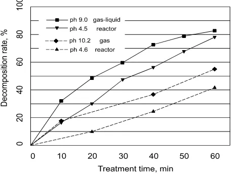
Figure 10 depicts the change of decomposition rate for both gas and gas-liquid reactors under different pH values. It can be deduced from the plot that the decomposition rate was lower in the acidic condition than in the basic condition with pulse discharge [41-42]. The reason for this result is that in the basic condition the ozone produced in the solution can be easily transformed into •OH, which possesses stronger oxidation capability than ozone, leading to higher decomposition efficiency [43].
Figure 10 Effect of PH variation on decompostion rate of gas and gas-liguid reactors [19-20]
7.0 CONCLUSION
Increasing population and consequently the increment in production of wastewater by different human activities have caused clean water to become critically important for the survival of our planet. Drawbacks in current water purification systems demand more cost effective, compact and efficient technologies. The present study reviewed the development of previous and current reactor electrode configurations that can be used to decompose phenol within aqueous solutions.
New technologies effectively replace traditional concepts. Gas-liquid phase electrical discharge produces hydrogen peroxide in water and ozone in the gas phase. Generated ozone in the gas phase results in higher concentrations of reactive
The authors gratefully acknowledge the support extended by the Ministry of Higher Education (MOHE), Malaysia and Universiti Teknologi Malaysia on the Fundamental Research Grant Scheme (FRGS), No. R.J130000.7823.4F054s, in order to carry out this work.
Fundamental Study and Industrial Applications. Journal Of
Electrostatics. 44; 17–39. Solutions. Hazard. Waste Hazard. Mater. 10: 209.
[4] H.-J. Wang and X.-Y. Chen. 2011. Kinetic Analysis And Energy
Efficiency of Phenol Degradation In A Plasma-Photocatalysis System. Journal Of Hazardous Materials. 186: 1888–1892.
[5] R. Xie, et al. 2010. Phenol Degradation By A Hybrid Gas-Liquid
Discharge Reactor With Digital-Analog Mixed Control. In Proceedings
Of The 29th Chinese Control Conference, Beijing, China. 5013–5016. [6] M. Sato, et al. 2008. Aqueous Phenol Decomposition By Pulsed
Discharges On The Water Surface. Ieee Transactions On Industry Applications. 44: 1397–1402.
[7] L. Xiaoyong, et al. 2012. Enhanced Degradation Of Phenol By Carbonate Ions With Dielectric Barrier Discharge. Ieee Transactions On Plasma Science. 40: 112–117.
[8] S. Mayank And R. L. Bruce. 2006. Degradation Of Chemical Warfare
Agent Simulants Using Gas–Liquid Pulsed Streamer Discharges. Journal Of Hazardous Materials. B137: 1025–1034.
[9] J. S. Clements, et al. 1987. Preliminary Investigation Of Prebreakdown Phenomena And Chemical Reactions Using A Pulsed High-Voltage Discharge In Water. Industry Applications, Ieee Transactions On. Ia-23: 224–235.
[10] B. Sun, et al. 1997. Optical Study Of Active Species Produced By A Pulsed Streamer Corona Discharge In Water. J. Electrostatics. 39: 189– 202.
[11] M. Muhammad Arif, et al.. 2002. Synergistic Effect Of Pulsed Corona Discharges And Ozonation On Decolourization Of Methylene Blue In Water. Plasma Sources Science And Technology. 11: 236.
[12] L. R. Grabowski, et al. 2006. Corona Above Water Reactor For
Systematic Study Of Aqueous Phenol Degradation. Plasma Chemistry
And Plasma Processing. 26: 3.
[13] W. F. L. M. Hoeben, et al. 1999. Gas Phase Corona Discharges For
Oxidation Of Phenol In An Aqueous Solution. J. Phys. D: Appl. Phys.
32: L133–L137.
[14] B. R. Locke, et al. 2005. Electrohydraulic Discharge And Nonthermal Plasma For Water Treatment. Industrial & Engineering Chemistry Research. 45: 882–905. 2006/02/01.
[15] M. Elsawah, Et Al. 2012.Corona Discharge With Electrospraying
System For Phenol Removal From Water. Ieee Transactions On
Plasma Science. 40: 29–34.
[15] H. Wang, et al.. 2007. Formation Of Hydrogen Peroxide And
Degradation Of Phenol In Synergistic System Of Pulsed Corona Discharge Combined With Tio2 Photocatalysis. J. Hazard. Materials. 141: 336–343.
[16] P. Lukes and B. R. Locke, 2005. Degradation Of Substituted Phenols In A Hybrid Gas–Liquid Electrical Discharge Reactor. Ind. Eng. Chem. Res. 44: 2921–2930.
[17] J. Li, et al. 2007. Degradation Of Phenol In Water Using A Gas–Liquid Phase Pulsed Discharge Plasma Reactor. Thin Solid Films. 515: 4283– 4288.
[18] W. Yan, et al. 2009. Decomposition Of Phenol In Water By Gas Phase
Pulse Discharge Plasma. In Industry Applications Society Annual Meeting, 2009. Ias 2009. Ieee. 1–4.
[19] H. Wang, et al. 2006. Decoloration Of Azo Dye By A Multi-Needle-To-Plate High-Voltage Pulsed Corona Discharge System In Water. Journal Of Electrostatics. 64: 416–421.
[20] M. Dors. 2010. Plasma For Water Treatment. Ed. Poland.
[21] M. Sato, et al. 2005. Decoloration Of Organic Dye In Water By Pulsed Dischcarge Plasma Generated Simultaneously In Gas And Liquid. J. Adv. Oxid. Technol. 8: 198–204.
[22] S. Kunitomo and S. Bing. 2001. Removal Of Phenol In Water By Pulsed High Voltage Discharge. In Pulsed Power Plasma Science, 2001. Ppps-2001. Digest Of Technical Papers. 2: 1138–1141. [23] A. A. Joshi, et al. 1995. Formation Of Hydroxyl Radicals, Hydrogen
Peroxide and Aqueous Electrons by Pulsed Streamer Corona Discharge In Aqueous Solution. Journal Of Hazardous Materials. 41: 3–30. [24] B. Sun, et al. 1999. Oxidative Processes Occurring When Pulsed High
Voltage Discharges Degrade Phenol In Aqueous Solution.
Environmental Science & Technology. 34: 509–513. 2000/02/01. [25] P. Sunka. 2001. Pulse Electrical Discharges In Water And Their
Applications. Phys. Plasmas. 8: 2587.
Oxidation Of Phenol In An Aqueous Solution. J. Phys. D: Appl. Phys. 32: L133.
[27] J. A. Robinson, et al. 1998. A New Type Of Ozone Generator Using Taylor Cones On Water Surfaces. Ieee Trans. Ind. Appl. 34: 1218. [28] D. R. Grymonpre, et al. 2003. Suspended Activated Carbon Particles
And Ozone Formation In Aqueous Phase Pulsed Corona Discharge Reactors. Ind. Eng. Chem. Res. 42: 5117–5134.
[29] J. Pawlat, et al. 2001. Studies On Electrical Discharge In A Foaming Environment. Jpn. J. Appl. Phys. 40: 7061.
[30] D. R. Grymonpre, et al. 2004. Hybrid Gas-Liquid Electrical Discharge Reactors For Organic Compound Degradation. Ind. Eng. Chem. Res. 43: 1975.
[31] P. Lukes, et al. 2004. Hydrogen Peroxide And Ozone Formation In Hybrid Gas–Liquid Electrical Discharge Reactors. Ieee Trans. Ind. Appl. 40: 60–67.
[32] P. Lukes, Et Al. 2004. Degradation Of Phenol In Hybrid Series Gas– Liquid Electrical Discharge Reactor. In Proceedings Of The Isntp4. Panama City, Fl, Usa. 120–125.
[33] K. Hrvoje, et al. 2005. Decomposition Of Phenol By Hybrid Gas/Liquid Electrical Discharge Reactors With Zeolite Catalysts. Journal of Hazardous Materials. B125: 190–200.
[34] A. T. Appleton. 2002. A Study Of The Effectiveness Of Different Hybrid Pulsed Corona Reactors In Degrading Aqueous Pollutants. M.S. Tesis, Dept. Chem. Eng., Florida State Uni., Tallahassee.
[35] A. T. Appleton, et al. 2002. Study Of Effectiveness Of Different Hybrid Pulsed Corona Reactors in Degrading Aqueous Pollutants. In
Contributed Papers HAKONE VIII, Puhajarve, Estonia. 313–317.
[36] H. Kusic, et al. 2002. Gas/liquid Hybrid Electrical Discharge Reactors for the Degradation of Organic Dyes and Phenol in Water. Presented at the 8th Int. Conf. Advanced Oxidation Technologies for Water and Air Remediation, Toronto, ON, Canada, Nov. 17–21.
[37] Y. S. Chen, et al. 2004. Pulsed High-voltage Discharge Plasma for
Degeradation of Phenol in Aqueous Solution. Separation and
Purification Technology. 34: 5–12.
[38] M. J. Kirkpatrick and B. R. Locke. 2005. Hydrogen, Oxygen, and Hydrogen Peroxide Formation in Aqueous Phase Pulsed Corona Electrical Discharge. Industrial & Engineering Chemistry Research. 44: 4243–4248. 2005/06/01.
[39] K. Faungnawakij, et al. 2006. Modeling of Experimental Treatment of Acetaldehyde-Laden Air and Phenol-Containing Water Using Corona Discharge Technique. Environmental Science & Technology. 40: 1622– 1628. 2006/03/01.
[40] P. S. Lang, et al. 1998. Oxidative Degradation of 2,4,6-Trinitrotoluene by Ozone in an Electrohydraulic Discharge Reactor," Environmental Science & Technology. 32: 3142–3148. 1998/10/01.
![Figure 1 Decomposition of phenol by oxidant radicals in liquid-phase [16]](https://thumb-ap.123doks.com/thumbv2/123dok/492426.426195/2.612.70.277.413.620/figure-decomposition-phenol-oxidant-radicals-liquid-phase.webp)
![Figure 6 Schematic illustration of the wire-cylinder reactor [24]](https://thumb-ap.123doks.com/thumbv2/123dok/492426.426195/3.612.57.293.479.682/figure-schematic-illustration-wire-cylinder-reactor.webp)
![Figure 8 Effect of solution conductivity on decompostion rate of gas and gas-liguid reactors [19-20]](https://thumb-ap.123doks.com/thumbv2/123dok/492426.426195/4.612.58.554.443.687/figure-effect-solution-conductivity-decompostion-rate-liguid-reactors.webp)